Note: Descriptions are shown in the official language in which they were submitted.
CA 02528064 2005-12-01
WO 2004/112702 PCT/US2004/018782
LOW DOSE PHARMACEUTICAL POWDERS FOR INHALATION
BACKGROUND OF THE INVENTION
Inhalation of aerosol powders from dry powder inhalers (DPI's) is a
convenient way of delivering drugs to patients, such as asthmatics. Current
DPI's
typically make use of small amounts of micronized drug blended with large
amounts
of carrier particles, such as a lactose carrier, to facilitate efficient
delivery of the drug
to the lungs. The efficiency and reproducibility of delivery of such blends is
dependent on the patient's lung function and can be effected by parameters
such as
inspiratory flow rate` and/or volume. Existing DPI's can be reservoir based,
such as
those capable of storing and delivering large numbers of doses to patients, as
well as
receptacle based, such as those utilizing capsules or blisters.
Patients that could benefit from drugs delivered via a DPI often times do have
compromised or reduced lung function, which can alter, reduce, or delay the
efficiency of delivery or therapeutic onset of the drug. Conditions leading to
such
compromised lung function include asthma, COPD, anaphylaxis, emphysema, and
other forms of respiratory distress. Other factors such as a patient's age
(i.e. children
or elderly patients), history (i.e. smoking, chemical exposure) and other
conditions
can also lead to a reduction of inspiratory flow rate and/or volume.
A need exists to be able to efficiently and reproducibly deliver therapeutic
agents to the lungs of such compromised patients. This would optimally utilize
low
masses of dry particles capable of being delivered via a single breath-
activated step,
especially at low inspiratory flow rates and/or low inspiratory volumes. Also,
a need
exists to deliver
a large fraction of the mass of such particles from the DPI to the pulmonary
system of
a compromised patient.
SUMMARY OF THE INVENTION
It is therefore an object of the invention to deliver an effective amount of
therapeutic, prophylactic or diagnostic agents by dry powder aerosols without
the
need for particle levels typically found with capsule-based delivery systems,
such as
those including a carrier.
CA 02528064 2005-12-01
WO 2004/112702 PCT/US2004/018782
2
It is therefore an object of the invention to deliver an effective amount of
therapeutic, prophylactic or diagnostic agents by dry powder aerosols having
lower
dose levels, for example, less than 5 mg.
It is another object of the invention to deliver an effective amount of
therapeutic, prophylactic or diagnostic agents by dry powder aerosols having
lower
dose levels, for example, less than 5 mg to compromised patients having low
inspi'ratory flow rates of less than 20 L/minute.
It is another object of the invention to deliver a dry powder aerosol with a
respirable fraction (<4.7 m) of 45% or more which maintains a high emitted
dose
over a very broad flow rate range, such as between 15-60 L/min.
The invention relates to a method of delivering an agent to the pulmonary
system of a compromised patient, in a single breath-activated step, comprising
administering a particle mass comprising an agent from an inhaler containing
less
than 5 milligrams of the mass, wherein at least about 50% of the mass in the
receptacle is delivered to the pulmonary system of the patient.
In another embodiment, the invention relates,to a receptacle containing less
than 5 milligrams of particle mass comprising an agent wherein, upon delivery
to the
pulmonary system of a compromised patient, in a single breath-activated step,
at least
about 50% of the mass in the receptacle is delivered to the pulmonary system
of the
patient.
Further, the invention relates to an inhaler for use in a method for
delivering
an agent to the pulmonary system of a compromised patient, in a single breath-
activated step comprising administering a particle mass comprising an agent
from an
inhaler containing less than 5 milligrams of the mass, wherein at least about
50% of
the mass in the receptacle is delivered to the pulmonary system of the
patient.
BRIEF DESCRIPTION OF THE FIGURES
The present invention is described with reference to the accompanying
drawings.
In the drawings, like reference numbers indicate identical or functionally
similar
elements.
FIG. 1 is a front view of one`embodiment of a device of the present invention;
FIG. 2 is a cross-section of the device shown in FIG. 1 along line 2-2;
CA 02528064 2005-12-01
WO 2004/112702 PCT/US2004/018782
3
FIG. 3 is an enlarged partial cross-section of one embodiment of a dispersion
chamber
of the present invention;
FIG. 4 is an enlarged partial cross-section of another embodiment of a
dispersion
chamber of the present invention showing one location for a ring in the
dispersion
chamber;
FIG. 5 is an enlarged partial cross-section of another embodiment of a
dispersion
chamber of the present invention showing another location for a ring in the
dispersion
chamber;
FIG. 6 is an enlarged partial cross-section of another embodiment of a
dispersion
chamber of the present invention showing another location for a ring in the
dispersion
chamber;
FIG. 7A is a top view of a preferred embodiment of a staple suitable for use
with the
device of the present invention;
FIG. 7B is a front view of the embodiment shown in FIG. 7A;
FIG. 7C is a side view of the embodiment shown in FIG. 7A;
FIG. 7D is an isometric view of the embodiment shown in FIG. 7A;
FIG.8 is a bar graph illustrating emitted dose at flow rates of 20 L/min (left
bar), 40
L/min (center bar), and 60 L/min (right bar) for four dispersion chamber
configurations;
FIG. 9 is a bar graph illustrating emitted dose at low flow rates for devices
with
varying numbers of slits;
FIG. 10 is a bar graph illustrating the percentage emitted dose as a function
of air
volume;
FIG. 11 shows radiolabeling validation data for the 5 mg placebo formulation;
FIG. 12 shows emitted dose (ED) as a function of pulmonary inspiratory flow
rate
(PIFR);
FIG. 13 shows the lung deposition of the total dose as a function of PIFR;
CA 02528064 2005-12-01
WO 2004/112702 PCT/US2004/018782
4
FIG. 14 shows AIR-epinephrine performance across inhalation flow rates;
FIG. 15 shows the emitted dose versus power for different inhalers;
FIG. 16 shows the fine particle fraction (%<3.3 microns) versus power for
different
inhalers: The Eclipse, C2S (preferred inhaler of the instant invention),
Diskhaler and
Inhalator;
FIG. 17 shows the emitted dose apparatus;
FIG. 18 shows the emitted dose as a function of flowrate;
FIG. 19 shows the emitted dose as a function of inhaled volume; and
FIG. 20' shows the lung deposition as a function of inhaled volume.
DETAILED DESCRIPTION
The invention relates to a method of delivering an agent to the pulmonary
system of a compromised patient, in a single breath-activated step, comprising
administering a particle mass comprising an agent from an inhaler containing
less
than 5 milligrams of the mass, wherein at least about 50% of the mass in the
receptacle is delivered to the pulmonary system of the patient.
Applicant have been improving methods of delivering particle masses, in
particular, dry particles for oral delivery. Applicant have discovered methods
to
deliver an effective amount of therapeutic, prophylactic or diagnostic agents
by dry
particles aerosols having lower dose levels, for example, less than 5 mg, in
particular,
in the range of 3 mg to 5 mg. Until the present invention, it has been a
challenge to
administer aerosols having lower dose levels, for example, less than 5 mg to
compromised patients having low inspiratory flow rates, for example, less than
20
L/minute. Applicant have been able to deliver a chemically stable dry particle
aerosol
with a respirable fraction (<4.7 m) of 45% which maintains a high emitted dose
(>80%) over a flow rate range of 15-60 L/min, that is, over a range of
inhalation flow
rates.
Compromised patients include individuals who do not or cannot breathe hard
or have a compromised lung function. Examples of such individuals include
children,
including growth hormone deficient children, elderly persons, persons
suffering from
CA 02528064 2005-12-01
WO 2004/112702 PCT/US2004/018782
respiratory disease, such as conditions leading to such compromised lung
function
include asthma, COPD, anaphylaxis, emphysema, and other fonns of respiratory
distress. Other factors such as a patient's age (i.e. children or elderly
patients), history
(i.e. smoking, chemical exposure) and other conditions can also lead to a
reduction of
5 inspiratory flow rate and/or volume. Other individuals include sleeping
individuals
and comatose individuals. Preferably, the individuals are vertical during the
method.
However, it is also possible to practice the method horizontally. Preferably,
human
growth hormone is administered to children at doses of less than 5 mg, such as
less
than 4 mg.
Generally, the individual will have a peak inspiratory flow rate (PIFR) of
less
than about 20 liters per minute. In one embodiment, the patient will have a
PIFR of
about 15 liters per minute or less. Alternatively or additionally, the
compromised
patient has a inspiration volume of less than 2 liters, such as less than 1.5
liters,
including less than 1 liter, such as 0.751iters.
The method is particularly useful in delivering agents that are useful in
treating the cause of the patient's compromised state, such as administering
epinephrine for treating or preventing anaphylaxis, growth hormone for growth
hormone deficient children, or asthma medications, such as albuterol,
fluticasone
formoterol, ipatroium bromide, trospium chloride or salmeterol, for treating
asthma.
A particular advantage of the invention rests in the discovery that delivery
of
very small amounts of drug (e.g. particle mass) can be achieved independently
of
PIFR. This unexpected discovery permits reliable and reproducible dosing for
the
patient, irrespective of the patient's particular condition and the need to
determine the
patient's actual flow rate prior to administering the dose, even at very low
doses of
particle mass.
Thus, in a preferred embodiment, the inhaler, or the receptacle which may be
disposed within the inhaler, contains less than 4 milligrams of the particle
mass,
preferably less than about 3 milligrams (such as about 3.4 mg). In one
embodiment,
the mass of particles contains epinephrine at a dose of about 250 to 750
micrograms
of epinephrine.
The particle mass is highly dispersible and possesses good to excellent
deposition in the lung. Examples of preferred particle masses possess a tap
density of
3
less than about 0.4 g/cm, preferably less than about 0.1 g/cm3, such as less
than about
CA 02528064 2008-11-12
WO 29940YJaZ
().03 g/cm3. Tap deaaity is a memm.o afftenve*cmeasdvaS1tyc~a
padck Uo aavdape 00 densiLLy of Pulii"-of aOWWadly i9otmpiC sbsQe ffi
dafinad as dye mass of the pazti* dlftd byilbe mWm= splim mvoiope V*mue
withmwhlah it m 6e end,ased..
Prdm=d pa.rbiclc mm posaess a msss maaa gpmcgic dysmetot of tiie
ma9s, as emittzd fi~ ~e iahalet, beraaeen abovt 1mfamand 20 miciw, sL,ah as
botweon about 3 and IS mimoas, mm pQafrsabiy Idaroan abont 3mnccoas aad 10
inicrans. Good dcpnsatiaa t4 tlvc htiog cm ba socl3ie~ viLth peztiele mas es
possessing a pmfemd mass meaa aaodynamia diamcter of the mass amiited fiom the
inBaler is betwem abont I te 511 kir- 1 q siuh as bdmeea ebouk 1 aed 3
micz+ans.
Prefeaed pa~icks masscs imcltidaoL ~oosist of spuY-dad+edpa;ticlM
peabmre.s thst can canlre'babelDlcrw tap dM*y. ]zFge=u*co &=
low aeludpnsmia dlsermm 1 nc11 3e hregularsutfixatraea d.bnllaworpmmus
sftuctm= ?&&dady prmtmuiPwddoav4lvzddes amde=bodiuU. S.Pabent
Nos. 6,136,295, 5,985,309, 5,874,064, 5,855,913, and 6,858,199.
Oti=paiclos tlw caa be asdni in the cU&mtd bvmfm incliude tlm
mautlcfted undor du tradamwk PULMO8P7gFR0% davel,oped byNektar
Theopcodm
mm methad af the iIIVentinu.msnlts iagoodta mceIluiL anaitDcd dpsec oftbc
pazt{clo mass. In cme am~odin~thrmai~ed ~oee ig ~ I~st Sil ~4pnelsr.~iy at 1~t
abaut 60%, %=prefetably a2lesstboadTO'1~. In aPardcdady p#enud
embodiment, the sdiaved emiAnd doae totbe gmkr thau.aboatS0% smhas stleagt
abowt$SX.
Mc matbod can be =adly acliaeved.asim,g anW%aZec d=isclaseciinthe piteax
spplicstion filed m. thc IInitod 3ts=P'amft& Tra&mar.iC Ofce mOcobtr 10,2002,
having the title "Inhalation Device and Method" by Edwards et al., U.S.
Publication No.
20030150453, published on August 14, 2003. Other inhalers that can be used
include
those described in PCT publication WO 02/083220, having the title "Inhalation
Device
and Method," by Edwards et al. published on October 24, 2002.
' ~ _
CA 02528064 2008-11-12
~Vd ~6~i1~71T !'CT/USmOtrOS978Z
7
AlDamIt io6afaa whl& cartbensad ia ft mdliodaedrypuederlmraiam
'rnalading oqmte londad inbdos. 13~mmples ofsiitablk dry pn,rder iaWcas lOOlWe
but are not Fmm{Oed ta te lnbalera 6=iWaoad 3a U.S.k'ate94,.995,385 and
4,069,819,
3PROAMR*(Flsaas, VU ROTAI3ALF.ttjGyoWSmi[~ NC). FLO'WCAPS *
(Hovivna, 3a-itrwlaud}, M1AI.ATOIL*(BoaFsn`&*db* Gc:maaY~
AMtoUZSR (NoosrKs, swlfze,daod), mdtbaNCi.ieSla (Avaofb) aaabfitw-basad
i6alers, snch as DEZEALER (GM NC), sad DISKtJS*(GS1C, NC).
The selecbed low amouats of ap'niapkie gudcles nsed ia tbac 1oe~ant
kmvution ue 336 mg pardeiC far deCivay of lawast dose (300 ug apbqhrbc) w6ich
is an amame#y 1ow powvdar domfowbbddkn. Ma aombkmdooa uftbs drypowdrr
aarosolwhh a r~rabla frar.~an (~k?pm.) of45Yo andthe preSeaed mhsler
mam~ed an uuea~ec:eadlp Li~ emil~ed ~~'Etis ~ n~otbe~lffty ~ t~t
higMy oontXaniisedPalieots aod btlmacobr, bighlY c,=Fvmbod dtUdrm
The Applioaat oomWod the obuh=C3R Ofthe iugant invention ag,3ID.5t
otixx avaiIabk WImotvgias. For eaampl, Oec cmitliod doac dftcompuftfis
Di"der, InLalator, Ecdipse aad C23 bhalar~ shown m l?YGs.15 and 16, atid.FPF
(96Ci3 zd=ns) wrn pre~ uftS.6 mg, aaa=pondiag to 500 pg ae(m
ephophriae whioh wae used ia fhe hcuen aiimmel triai pafmmed by AFPrwoaL
Inspiratory flow rates of 15.30 iod 60 Umin with a total volwua of 2liteis wae
used
far aU tLn inLalers and thea plcftdaspowrs ('m vratts) vasos emmWdose. Power
is
a limcAn offlowrate aad negowoe wM eik ia~6attcslad Imft a fiffla+emt
roslstanee.
The fofmula used tn eakulale Pawar im
Pawa - Fbwrate3 xR=btMCX2
As mdicxicd bytba rsft tbe coepmbea dnrradtbatattixiow Scwrm
of 15 L/min iMasmmaffc Er~iao~ 6t s eau~a3 at~e (oosr~poi~ tia 1ess tL~u
0.5 ws~ts paw~erforall'a~6aleea te~opd) theEn is a$alI off'm emimeddoxfor ail~
mhal.ers except EortLe C2S imhal=, aj d~ed I~slor 8os the Fmrt imrenAon.
Thc se~e ~.~ae par6o ed.~iba bwae,pl~rioa 5tl
weight of 336 mg:Tbis coa=pands to 300 g epiil;ipfac sLl5 llndn. Tbe
e+atitbed
dowwas=wmrcdand tbe dgashaovu ut F'Wxt 14,d=mMfttlmt Iess dam.
*Trademazk
CA 02528064 2005-12-01
WO 2004/112702 PCT/US2004/018782
8
about 5 mg particle mass were developed at less than about 20 L/min. More
particularly, as shown, the emitted dose data for a 3.36 mg filled capsule is
shown in
FIG. 14. This compares favorably to the previous emitted dose data generated
for the
5.6 mg fill weights.
Applicant employed two methods to obtain a measure of the emitted dose. A
gravimetric analysis and a chemical analysis. Applicant performed the analysis
according to the standard operating procedure (SOP) described below.
Applicant tested the particles under controlled environmental conditions of a
room temperature of greater than about 18 C but less than about 25'C and a
relative
humidity of between about 20 and about 40. The equipment used in the Examples
is
shown in Figure 17.
In performing the tests, a filled capsule was placed in the inhaler. Holding
the
inhaler vertically with the mouthpiece up, the capsule was punctured. The
inhaler
was placed in the inlet of the apparatus shown in Figure 17, ensuring an
airtight seal.
Next the pump was activated using the flow controller. The flow rate selected
was
either 60 ( 2) L/min for 2 seconds or a flow rate of 30 ( 2) L/min for 4
seconds or a
flow rate of 15 L/min for 8 seconds. In order to ensure that an airtight seal
was
attained, an equal flow rate was maintained in both meters ( 2 L/min).
After performing the experiments and collecting the data, using the following
formulae, the emitted dose was calculated.
ED= 11- m n x 100
m
fi-'
Where ED [%] is the emitted dose of the particles and mjo [mg] is the mass of
the
filter, mfl [mg] is the mass of the particle-laden filter and mfw [mg] is the
actual or
nominal fill weight.
Experiments in humans were conducted to evaluate the in vivo dose delivery
characteristics of the delivery system of the instant invention over a wide
range of
inspiratory flow rates. The in vivo dose delivery of the pulmonary delivery
system of
the instant invention was characterized at a target peak inspiratory flow rate
(PIFR) of
60 L/min (Dunbar et al., Int. J. Pharm. 245, 2002).
Twelve healthy volunteers participated in a single center, randomized, three
period, cross-over study. Each volunteer performed the following three
inhalation
CA 02528064 2005-12-01
WO 2004/112702 PCT/US2004/018782
9
maneuvers: (i) a targeted peak inspiratory flow rate (PIFR) of 20 L/min, (ii)
a deep
comfortable inhalation, and (iii) a deep forced inhalation. Volunteers inhaled
the
radiolabeled placebo particles sitting upright, with their head and lungs
posterial to
the planar gamma camera. After a 5 s breath hold, the volunteers were
instructed to
exhale into a filter. Peak inspiratory flow rate (PIFR) and inhaled volume (V)
were
obtained during the inhalation of the dose using a spirometer (Koko
Spirometer,
Pulmonary Data
Services Inc., Louisville, CO). Immediately following the radiolabeled dose,
posterior scintigraphic images were taken using a planar gamma camera (DIACAM,
Siemens Gammsonics, Inc., Hoffman Estates, IL). Four regions of interest were
drawn around the left lung, right lung, stomach, and oropharynx (which
included the
upper part of the trachea). After subtracting the background activity, each
region was
corrected for tissue attenuation. The radioactivity in the pre-dosed capsule
and the
radioactivity remaining in the inhaler mouthpiece, inhaler body, post-dosed
capsule,
and exhalation filter were measured by scintigraphy using a high sensitivity
NaI
detector (Model 905, Perkin-Elmer, Oak Ridge, TN). PIFR, emitted dose (ED),
and
lung deposition of the total dose
were evaluated in this study.
The mean ED and lung deposition across all three inhalation maneuvers were
87 (4)% and 51 (10)%, respectively (sd in parentheses). The range of PIFRs
obtained
in this study was 12-86 L/min. The emitted dose and the lung deposition of the
total
dose as a function of PIFR are shown in the figures.
In conducting the human scintigraphy, 5 mg placebo was delivered via a
simple, capsule based, passive dry powder inhaler such as the preferred
inhaler
described herein. The particles was radiolabeled with 99mTc using a fluidized
bed
process (Dunbar et al., Int. J. Pharm., 245, 2002). Validation experiments
were
conducted to ensure the radiolabeling process did not significantly affect the
aerodynamic particle size distribution (aPSD) of the emitted dose and the
radioactive
aPSD matched the mass aPSD. The mass aPSD of the unlabeled particles, the mass
aPSD of the labeled particles, and the radioactive aPSD of the labeled
particles were
obtained using an 8-stage Andersen cascade impactor (Andersen Instruments,
Smyrna, GA) with a USP induction port, shown in Figure 11.
CA 02528064 2005-12-01
WO 2004/112702 PCT/US2004/018782
In a preferred embodiment, the inhaler comprises: a first casing portion; a
cylindrical chamber, defined by a wall of circular cross-section, coupled to
the first
casing portion, the chamber having a proximal end and a distal end, the
chamber
comprising a ring circumferentially coupled to an inner surface of the
chamber; and a
5 second casing portion removably coupled to the first casing portion, the
second casing
portion comprising an inhalation portion disposed at the proximal end of the
chamber
when the first and the second casing portions are coupled, the inhalation
portion
comprising a hemispheric region defining a plurality of apertures configured
to emit
the mass.
10 As will be described in more detail below, an apparatus of the present
invention is an inhaler that includes a chamber. In one embodiment, the
chamber is
configured to receive the receptacle containing the medicament. To improve the
emptying of the receptacle and provide a higher reproducible emitted dose, the
chamber includes a ring circumferentially coupled to an inner surface of the
chamber.
The ring is preferably disposed at approximately a midpoint of the chamber, or
alternatively, adjacent the proximal end of the chamber. In proper use, air
will exit the
inhaler carrying a full dose of medicament in the form of a fine, dry particle
mass.
The inhaler of the present invention is preferably configured with a means for
puncturing the receptacle that improves puncturing performance, particularly
with
brittle receptacle material. The means for puncturing the receptacle of the
present
invention is preferably configured as a substantially U-shaped staple with two
prongs,
each prong having a sharp point and two cutting edges. In one embodiment of
the
present invention, each prong has a square cross-section, with the staple
material
being bent around a face so that the innennost part of the U-shaped staple is
flat. In
another embodiment of the present invention, the staple material is rotated 45
degrees
so that it is bent around an edge so that the innerinost part of the U-shaped
staple is an
edge. In such an embodiment, the end surface of each prong is an angled
diamond-
shaped surface.
The methods of the present invention use an inhaler to dispense particle by
inhalation. As will be discussed in greater detail below, a user operates the
device to
puncture the receptacle to disperse particles in the chamber, and inhales the
particles
through the inhalation portion.
CA 02528064 2005-12-01
WO 2004/112702 PCT/US2004/018782
11
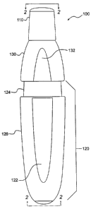
A front view of one embodiment of an inhalation device 100 of the present
invention is shown in FIG. 1. The rear view of device 100 is substantially
identical to
the front view. Device 100 includes a first or lower casing portion 120 and a
second
or upper casing portion 130 removably coupled to first casing portion 120.
Upper
casing portion 130 and lower casing portion 120 include a flattened region 132
and
122, respectively, for ease of gripping the casing for use by a patient. Lower
casing
portion 120 preferably includes an outer casing 126 and an inner casing 124
movably
received within outer casing 126. A removable cap 110 is provided at the user
or
inhalation end of the device.
Preferred materials for device 100 include Food and Drug Administration (FDA)
approved, USP tested plastics. Preferably, device 100 is manufactured using an
injection molding process, the details of which would be readily apparent to
one
skilled in the art.
FIG. 2 is a cross-section of device 100 shown in FIG. 1 along line 2-2. As
shown in
FIG. 2, device 100 includes an inhalation or emitter portion 220. Inhalation
portion
220 comprises a hemispheric region 222 that defines a plurality of apertures
224. It
should be understood that the present invention is not limited to a particular
number
of apertures 224, and can be configured such that at least one aperture 224 is
provided. An inhalation piece 226 is provided to allow for inhalation of the
medicament by a user.
Inhalation piece 226 can be configured as a mouth piece for inhalation through
a user's mouth. Alternatively, inhalation piece 226 can be configured as a
nose piece
for inhalation through a user's nose.
Device 100 includes a cylindrical chamber 210 that is defined by a straight
wall 212 of circular cross-section. Chamber 210 has a proximal end 214 and a
distal
end 216.
A plurality of slits 218 are defined by wall 212, and are configured for
introducing air
into chamber 210 to disperse particles released from a capsule 219. It should
be
understood that the present invention is not limited to a particular number of
slits 218,
and can be configured such that at least one slit 218 is provided. Particles
released
from capsule 219 is dispersed in chamber 210 and inhaled through apertures 224
and
inhalation piece 226 by the user.
CA 02528064 2005-12-01
WO 2004/112702 PCT/US2004/018782
12
In other embodiments of the invention, receptacles other than capsules are
used, such as blisters and film covered container wells as is known in the
art. In one
embodiment, the volume of the receptacle is at least about 0.37 cm3. In
another
embodiment, the volume of the receptacle is at least about 0.48 cm3. In yet
another
embodiment, the receptacles have a volume of at least about 0.67 cm3 or 0.95
cm3. In
one embodiment of the invention, the receptacle is a capsule designated with a
capsule size 2, 1, 0, 00, or 000. Suitable capsules can be obtained, for
example, from
Shionogi (Rockville, MD). Blisters can be obtained, for example, from Hueck
Foils,
(Wall, NJ).
The receptacle encloses or stores particles, also referred to herein as
powders.
The receptacle is filled with particles in a manner known to one skilled in
the art. For
example, vacuum filling or tamping technologies may be used. Generally,
filling the
receptacle with powder can be carried out by methods known in the art.
Device 100 includes a means for puncturing 230 that is used to puncture
capsule 219 to release particles contained therein into chamber 210. In the
embodiment shown in FIG. 1, means for puncturing 230 is configured as a
substantially U-shaped staple having two prongs 232. In this embodiment, each
of
prongs 232 is configured with a square cross-section 234, thereby providing a
sharp
point and two cutting edges. As discussed in more detail below, device 100
could
alternatively be configured with the puncturing implement shown in FIGS. 7A
through 7D. As can be readily appreciated by one skilled in the art, the
present
invention is not limited to use of a substantially U-shaped staple as the
means for
puncturing the capsule. Alternatively, one, or a plurality of, straight needle-
like
implements could be used. Preferably, the puncturing implement is configured
to
puncture at least two holes in the capsule.
Means for puncturing 230 is preferably configured to be movable between a
non- puncturing position (as depicted in FIG. 1) and a puncturing position. In
the
puncturing position, prongs 232 pierce or puncture capsule 219 to make holes
therein.
In a preferred embodiment, a means for biasing is provided that biases the
means for
puncturing 230 in the non-puncturing position. In the embodiment shown in FIG.
2,
the means for biasing is configured as a spring 242 that biases the
substantially U-
shaped staple in the non- puncturing position.
CA 02528064 2005-12-01
WO 2004/112702 PCT/US2004/018782
13
As noted with respect to FIG. 1, device 100 includes inner casing 124 and
outer casing 126. As shown in FIG. 2, a spring 244 is disposed in lower casing
portion
120 that biases inner casing 124 in an outward position. Upon compression of
spring
244, inner casing 124 moves from the outward position to an inward position,
thereby
drawing lower casing portion 120 toward upper casing portion 130. Compression
of
spring 244 also causes compression of spring 242, thereby causing means for
puncturing 230 to move to the puncturing position. Upon release of
compression,
springs 242 and 244 return to their biased state, thereby returning means for
puncturing 230 to its non- puncturing position, and inner casing 124 to its
outward
position.
A pair of flanges 252 is disposed on first casing portion 120. A pair of
grooves
254 is disposed on second casing portion 130 so that flanges 252 can be
received
within grooves 254 to thereby couple the first and second casing portions.
Preferably,
the first and second casing portions are coupled with a friction-fit
engagement. A
friction-fit engagement can be achieved using the groove and flange
arrangement
depicted in FIG. 2.
Other alternative configurations for a friction-fit engagement would be
readily
apparent to one skilled in the art.
FIG. 3 is an enlarged partial cross-section of one embodiment of chamber 210.
In the embodiment shown in FIG. 3, chamber 210 does not contain a ring
disposed on
an inner surface, and an inner diameter of chamber 210 is depicted as "X".
Such a
configuration may be referred to herein as a "straight" chamber configuration.
FIG. 4 is an enlarged partial cross-section of another embodiment of chamber
210. In
the embodiment shown in FIG. 4, a ring 400 is circumferentially coupled to an
inner
surface of chamber 210. An inner diameter of ring 400 is depicted as "Y", and
is less
than inner diameter X of chamber 210. In the embodiment shown in FIG. 4, ring
400
is disposed at approximately a midpoint of chamber 210. Such a configuration
may be
referred to herein as a "low" ring position or "low" chamber configuration. As
shown
in FIG. 4, in the low ring position, ring 400 is disposed adjacent slits 218.
The ring
position is measured by the distance from the top of hemispheric region 222 to
the
bottom edge of ring 400. This distance is depicted as "Z". The following
dimensions
are provided as exemplary dimensions of a device of the present invention. It
should
be understood by one skilled in the art that the present invention is not
limited to the
CA 02528064 2005-12-01
WO 2004/112702 PCT/US2004/018782
14
dimensions provided herein, or to any particular dimensions. In one embodiment
of
the chamber 210 shown in FIG. 4, diameter X is 0.47 in., diameter Y is 0.38
in., and
distance Z is 0.49 in.
FIG. 6 is an enlarged partial cross-section of another embodiment of chamber
210. In the embodiment shown in FIG. 6, ring 400 is circumferentially coupled
to an
inner surface of chamber 210. An inner diameter of ring 400 is depicted as
"Y", and is
less than inner diameter X of chamber 210. In the embodiment shown in FIG. 6,
ring
400 is disposed adjacent the proximal end of chamber 210. Such a configuration
may
be referred to herein as a "high" ring position or a "high" chamber
configuration. The
ring position is measured by the distance from the top of hemispheric region
222 to
the bottom edge of ring 400. This distance is depicted as "Z". The following
dimensions are provided as exemplary dimensions of a device of the present
invention. It should be understood by one skilled in the art that the present
invention
is not limited to the dimensions provided herein, or to any particular
dimensions. In
one embodiment of the chamber 210 shown in FIG. 6, diameter X is 0.47 in.,
diameter
Y is 0.38 in., and distance Z is 0.29 in.
FIG. 5 is an enlarged partial cross-section of another embodiment of chamber
210. In the embodiment shown in FIG. 5, ring 400 is circumferentially coupled
to an
inner surface of chamber 210. An inner diameter of ring 400 is depicted as
"Y", and is
less than inner diameter X of chamber 210. In the embodiment shown in FIG. 5,
ring
400 is disposed between the low ring position of FIG. 4 and the high ring
position of
FIG. 6.
Such a configuration may be referred to herein as a "mid" ring position or
"mid" chamber configuration. The ring position is measured by the distance
from the
top of hemispheric region 222 to the bottom edge of ring 400. This distance is
depicted as "Z". The following dimensions are provided as exemplary dimensions
of a
device of the present invention. It should be understood by one skilled in the
art that
the present invention is not limited to the dimensions provided herein, or to
any
particular dimensions. In one embodiment of the chamber 210 shown in FIG. 5,
diameter X is 0.47 in., diameter Y is 0.38 in., and distance Z is 0.39 in.
In one embodiment of the present invention, ring 400 is integral with chamber
210. In such an embodiment, ring 400 and chamber 210 are formed as a unit,
such as
through an injection molding, extrusion or a casting process. In another
embodiment
CA 02528064 2005-12-01
WO 2004/112702 PCT/US2004/018782
of the present invention, ring 400 is attached to the inner surface of chamber
210 in a
manner known to those skilled in the art, such as through the use of glue or
other type
of adhesive, or by using an attaching device such as a pin or screw, etc.
Preferably,
the casing of device 100 is made from a material that can be injection molded,
such as
5 a plastic material (preferably FDA approved, USP tested). As would be
readily
apparent to one skilled in the art, the material is preferably durable, easy
to clean, and
non-reactive with particles medicaments.
FIG. 8 is a bar graph illustrating emitted dose at flow rates of 20 L/min
(left
bar), 40 L/min (center bar), and 60 L/min (right bar) for a total volume of 2L
for four
10 dispersion chamber configurations (standard deviations shown; sample size
(n=3)).
The flow rates were measured with a flow meter. The emitted dose measurement
involved placing a capsule into four embodiments of the inhaler of the present
invention for actuation into an emitted dose (ED) measurement apparatus. The
ED
apparatus included a powder filter and a filter holder. The particles
collected by the
15 ED apparatus were quantified by fluorescence spectrophotometry. The
straight
configuration is shown in FIG. 3; the low configuration is' shown in FIG. 4;
the mid
configuration is shown in FIG.
5; and the high configuration is shown in FIG. 6. As can be seen from FIG. 8,
each of
the low, mid, and high configurations demonstrated a higher emitted dose at
each of
the three flow rates than the straight (no ring) configuration. Thus, the ring
configuration of the present invention provides an improvement over
conventional
chamber designs without a ring. At each of the flow rates shown in FIG. 8, the
low
configuration produced a higher emitted dose and a lower standard deviation
than the
mid and high configurations.
FIG. 9 is a bar graph illustrating emitted dose at low flow rates for devices
with varying numbers of slits 218. A flow rate of less than about 15 L/min
will be
referred to herein as a "low flow rate." The measurements were taken at a flow
rate of
5 L/min, with a volume of 67 cc and a 15 mg dosage. As show in FIG. 9, by
decreasing the number of slits 218, the emitted dose increases so that the
device of the
present invention successfully delivers a high emitted dose at low flow rate
over
multiple (ten) actuations.
Thus, the device of the present invention achieves a high emitted dose at low
flow
rates that is consistently reproducible with low standard deviation.
CA 02528064 2005-12-01
WO 2004/112702 PCT/US2004/018782
16
Experiments were conducted to evaluate the emitted dose as a function of air
volume drawn through the inhaler. The inhaler was operated at a constant flow
rate of
30 L/min for a 5 mg dose. The volume of air through the inhaler was varied by
varying the actuation time. Volumes of 0.5, 1.0, 1.5, 2.0 and 3.0 L were
investigated.
FIG. 10 shows the percentage emitted dose as a function of air volume (n=3,
standard
deviations shown).
The emitted dose remained constant across the range of volumes and was
consistently reproducible with low standard deviation.
In the embodiments having the inner diameter X of chamber 210 of 0.47 in.
and the inner diameter Y of ring 400 of 0.38 in., the ratio of the inner
diameter of the
ring to the inner diameter of the chamber is about 0.8. By modifying the inner
diameters of the ring and the chamber, it is possible to optimize the emitted
dose at
varying flow rates. As reported in Annals of the ICRP, Human respiratory tract
model
for radiological protection, 24 (1-3), Elsevier Science, New York, 1994, the
flow rate
for a tidal breathing seated adult male is 300 mL/s (18 L/min) for a volume of
750
mL. In one embodiment of a device of the present invention optimized for low
flow
rates (less than about 15 L/min), inner diameter X of chamber 210 is Q. 33 in.
and
inner diameter Y of ring 400 is 0.30 in. In such an embodiment, the ratio of
the inner
diameter of the ring to the inner diameter of the chamber is about 0.9.
Preferably, the
ratio of the inner diameter of the ring to the inner diameter of the chamber
is about 0.9
or less.
The device of the present invention can also be optimized for varying dosage
ranges. One way to do so is to vary the dimensions of chamber 210 to
accommodate
varying sizes of capsules. For example, a chamber having an inner diameter X
of 0.33
in., inner diameter Y of 0.30 in., and distance Z of 0.57 in. can be used with
size 2 and
size 00 capsules. One skilled in the art can scale chamber 210 to accommodate
varying capsule sizes, and to accommodate those capsule sizes at varying flow
rates.
The present invention further encompasses optimizing the configuration of
device chamber 210 in order to maintain a low resistance of 0.28 (cm
H20)"2/L/min
or less and to achieve an emitted dose of at least 50% when the receptacle
contains a
dose of up to 5 mg of particles and when the device is operated at a peak
inspiratory
flow rate of 20 L/min or less and/or at an inhalation volunie of 0.75 L or
less.
Experiments were performed on various chamber configurations, using size 00
CA 02528064 2005-12-01
WO 2004/112702 PCT/US2004/018782
17
capsules filed with a 20 mg dose of standard test powder. The various
configurations
were tested for emitted dose (ED), using known methods described above, at
peak
inspiratory flow rates ranging from 15 L/min to 25 L/min and at inhalation
volumes
ranging from 0.25 L/min to 0.75 L/min. In addition, the dispersion of the
particles
was quantified by measuring the volume mean geometric diameter (VMGD) of the
emitted particles, by employing a RODOS dry powder disperser (or equivalent
technique) such that at about 1 Bar, particles of the dry powder emitted from
the
RODOS orifice with geometric diameters, as measured by a HELOS or other laser
diffraction system, are less than about 1.5 times the geometric particle size
as
measured at 4 Bar. In addition, the resistance of each chamber was measured
using
methods that will be apparent to one of ordinary skill in the art.
The following dimensions of chamber 210 were varied in order to discover the
optimal combination: mouthpiece hole area, mouthpiece hole number, chamber
diameter (X in FIG. 4), ring diameter (Y in FIG. 4), vent area (the product of
vent
width, vent height, and vent number), and capsule hole area (the product of
the hole
area and the number of holes). Initially, it was discovered that it is always
desirable
to maximize the capsule hole area. Accordingly, the capsule hole area was
fixed at
0.013 square inches. It should be understood that the present invention
encompasses
other capsule hole areas, especially when used with different sized capsules.
It was
also determined that the total area of the holes in the mouthpiece was an
important
factor but that the number of holes in the mouthpiece did not effect the
results.
Next, 130 chambers were tested, each having a different combination of
mouthpiece hole area, chamber diameter, ring diameter, and vent area. During
the
testing it was discovered that each of these dimensions have competing effects
on the
emitted dose, the volume mean geometric diameter, and the resistance of the
chamber.
For example, increasing the vent area has a positive impact on (i.e.,
decreases)
resistance, but has a negative effect on (i.e., decreases) emitted dose and
has a
negative effect on (i.e., increases) volume mean geometric diameter. Other
dimensions have similar competing effects. In addition, as discussed in detail
below,
the vent area and the chamber diameter have combinational effects on the
properties
of the chamber. Other combinations of dimensions have similar combinational
effects.
CA 02528064 2005-12-01
WO 2004/112702 PCT/US2004/018782
18
Of the 130 chambers tested, three preferred embodiments of chambers were
identified that achieved the desired characteristics. The pertinent dimensions
of each
of those chambers is described in Table 1.
Table 1: Aspects of Preferred Embodiments of Chambers
Chamber F Chamber H Chamber I
Resistance (cm HZO) /L/min 0.27 0.22 0.19
Mouthpiece Hole Area (sq. in.) 0.020 0.022 0.022
Chamber Diameter (in.) 0.440 0.436 0.440
Ring Diameter (in.) 0.400 0.380 0.400
Vent Area (sq. in.) 0.014 0.020 0.024
Vent Number (in.) 3 4 5
Vent Width (in.) 0.020 0.025 0.020
Vent Length (in.) 0.236 0.195 0.236
Tables 2-4 summarize the emitted dose (ED) (in percent) and dispersion
(volume mean geometric diameter (VMGD) in microns)) (with standard deviations
in
parentheses) achieved with each of these preferred embodiments of chambers,
operated with a capsule having a dose of approximately 20 mg and at peak
inspiratory
flow rates from 15 L/min to 25 L/min and at inhalation volumes from 0.25 L to
0.75
L. The test particle mass, referred to herein as "standard test powder," was a
placebo
powder of 84.99 wt% maltodextran, 15 wt% leucine, and 0.01 wt% rhodamine. It
had
a VMGD of 12 m measured using the RODOS at 1 bar and an aerodynamic size
(volume mean aerodynamic diameter or VMAD) of 3 m measured using an 8 stage
Anderson Cascade Impactor. The goal emitted dose was at least 85%. The goal
dispersion for the standard test powder was a VMGD of 11.8 m or less,
although it
should be understood that this goal would vary depending on the type of powder
used.
CA 02528064 2005-12-01
WO 2004/112702 PCT/US2004/018782
19
Table 2: Chamber F
Volume--> 0.25 L 0.5 L 0.75 L
Flow Rate VMGD ED VMGD ED VMGD ED
15 L/min 15.0 (0.8) 67 (14) 13.5 (0.8) 87 (6) 16.4 (1.6) 93 (3)
20 L/min 10.2 (0.5) 66 (9) 9.3 (0.6) 89(4) 9.0 (0.6) 88 (10)
25 L/min 9.3 (0.6) 77 (8) 7.8 (0.3) 91(5) 7.9 (0.5) 93(3)
Table 3: Chamber H
Volume-+ 0.25 L 0.5 L 0.75 L
Flow Rate VMGD ED VMGD ED VMGD ED
15 L/min 16.1 (0.8) 57 (9) 15.7 (0.7) 78 (11) 14.6 (1.1) 90 (4)
20 L/min 12.0 (0.6) 66 (9) 10.4 (0.6) 81.(7) 10.2 (0.4) 89 (8)
25 L/min 10.4 (0.6) 75 (11) 8.1 (0.3) 94(4) 8.2 (0.3) 97 (1)
Table 4: Chamber I
Volume-> 0.25 L 0.5 L 0.75 L
Flow Rate VMGD ED VMGD ED VMGD ED
L/min 18.2 (0.7) 49(8) 19.3 (1.3) 69 (12) 18.2 (1.9) 79(12)
L/min 13.4 (0.5) 43 (13) 12.7 (1.0) 71 (10) 12.5 (0.6) 83 (9)
L/min 12.0(0.4) 65(8) 10.0(0.4) 85(7) 9.7(0.3) 87(9),
In Tables 2-4, the italicized print indicates peak inspiratory flow rates and
inhalation volumes at which the chambers achieved both the goal of an emitted
dose
10 of at least 85% and a dispersion of a VMGD of 11.8 m or less. As is
apparent from
Tables 2-4, these goals were achieved for peak inspiratory flow rates of 25
L/min or
less and for inhalation volumes of 0.75 L or less. Moreover, the standard
deviations
were quite small for the emitted dose (on the order of approximately 10% or
less) and
for the VMGD (on the order of approximately 1.0 or less).
15 In addition, statistical analysis was used to extrapolate the results from
these
three chambers into ranges of variables that would consistently yield the
desired
emitted dose and volume mean geometric diameter. For example optimized
combinations of chamber diameter, vent area, and mouthpiece hole area were
CA 02528064 2005-12-01
WO 2004/112702 PCT/US2004/018782
determined. It should be apparent to one of ordinary skill in the art that
optimization
analysis could be performed for other variable combinations, and for other
capsule
sizes and powders, in order to optimize the design of the chambers.
Having done a thorough analysis, it has been determined that the present
5 invention encompasses an optimized chamber, for a size 00 capsule, that has:
at least one aperture has an aggregate area of 0.018 to 0.022 square inches;
or
a ring inner diameter of 0.380 to 0.400 inches; or
a chamber inner diameter of 0.400 to 0.440 inches; or
three to five vents; or
10 a vent width of 0.020 to 0.025 inches; or
a vent length of 0.195 to 0.236 inches; or
a total vent area of 0.014 to 0.024 square inches,
and that when used with a dose of approximately 20 mg of the standard test
powder described above and operated at a peak inspiratory flow rate of 25
L/min or
15 less and an inhalation volume of 0.75 L or less, the emitted dose of powder
will be at
least 85%, and the VMGD will be about 11.8 m or less.
While the preferred embodiment described above relates to optimizing the
design of a chamber to have a resistance of at most 0.28 (cm H20)1/2/L/min and
to
provide an emitted dose of at least 85% when the dose of standard test powder
is
20 about 20 mg and when the device is operated at a peak inspiratory flow rate
of 25
L/min or less and at an inhalation volume of 0.75 L or less it should be
understood
that the invention also encompasses optimizing the chamber to have any other
combination of resistance and emitted dose, at any other combination of powder
type,
dose weight, peak inspiratory flow rate, and inhalation volume.
Turning now to FIGS. 7A through 7D, a preferred embodiment of a staple
suitable for use in the present invention is shown. The staple preferably
comprises a
rectangular length of material that has four planar side surfaces 730. Each
planar side
surface intersects with two other planar side surfaces to create a total of
four non-
planar edges 736. The staple is preferably bent into a substantially U-shaped
configuration, thereby having a rounded portion and two prongs 732. The prongs
732
terminate at two end surfaces 731. As best seen in FIGS. 7A, 7C and 7D, end
surfaces
731 are diamond- shaped.
CA 02528064 2005-12-01
WO 2004/112702 PCT/US2004/018782
21
The diamond-shaped end surfaces are created by bending the material about a
non-planar edge. This configuration is best shown in FIGS. 7B and 7D. As can
be
seen, each prong 732 has an inner surface 738 that comprises one of the non-
planar
edges and an outer surface 740 that comprises the opposite non-planar edge.
The inner
surface 738 of each prong 732 terminates at the uppermost portion 737 of the
diamond-shaped end surface, thereby creating a cutting edge for the prong. The
outer
surface 740 of the prong 732 terminates at the lowermost portion 735 of the
diamond-
shaped end surface.
Another embodiment of a staple suitable for use in the present invention
comprises a rectangular length of material that has four planar side surfaces.
Each
planar side surface intersects with two other planar side surfaces to create a
total of
four non-planar edges. The staple is preferably bent into a substantially U-
shaped
configuration, thereby having a rounded portion and two prongs.
The holes formed by this staple have the appearance of being cut with a sharp
edge. In addition, the material removed to create the hole is peeled back and
remains
well attached to the capsule; thereby preventing the capsule material from
being
inhaled by the user when the medicament is being dispensed.
In addition to improved puncturing performance, drug delivery from capsules
punctured with the staple depicted in FIGS. 7A-7D is greatly improved. The
Emitted
Dose (ED) and Fine Particle Fraction (FPF) of a test powder was measured at
both 20
and 60 Liters per minute (LPM). In all cases, the aerosol emitted from
capsules
punctured with the diamond section staple of FIGS. 7A-7D was improved over a
conventional circular stock staple. Most significantly, the FPF of powder
delivered at
20 liters per minute was improved almost to the level of the FPF at 60 liters
per
minute.
The present invention also relates to a method for dispensing medicaments to a
user through the various einbodiments of the disclosed inhalation device. In
such a
method, a receptacle containing the medicament, e. g., a capsule 219, is
placed or
formed into cylindrical chamber 210. When the user compresses the inhalation
device, staple 230 is moved toward capsule 219 thereby puncturing capsule 219
to
cause the release of particles masses into chamber 210. After release into the
chamber, the powder is then inhaled by the user through apertures 224 and
inhalation
CA 02528064 2005-12-01
WO 2004/112702 PCT/US2004/018782
22
piece 226. As noted, inhalation piece 226, can be configured as either a mouth
piece
or a nose piece.
For subsequent uses, the user merely replaces emptied capsule 219 with
another capsule 219 that contains a new supply of inedicament. Alternatively,
medicament is injected into a permanent receptacle that is formed into chamber
210.
Exemplification
Example 1
Particles containing epinephrine made in accordance with the method
described in United States Application No. 60/425,349, which is incorporated
herein
by reference, were used.
Example 2
Applicant employed two methods to obtain a measure of the emitted dose. A
gravimetric analysis and a chemical analysis. This example is a standard
operating
procedure (SOP) describing the method for obtaining the emitted dose using
gravimetric analysis. This procedure relates to the release and stability
testing of
Applicant's products.
Unless otherwise indicated the following equipment, supplies, reagents and
materials were used for both the Gravimetric analysis and the chemical
analysis.
-47 mm filter holder (e.g. BGI, Inc., Waltham, MA)
-Filter holder stand
-Flow meter (e.g. Mode132915-70 or equivalent, Cole-Parmer, Vernon Hills,
IL)
-Flow controller (e.g. Model TPK, Erweka USA, Inc, Milford, CT)
-Vacuum pump (e.g. Model 1023-101Q-G608X, Gast MFG. CORP., Benton
Harbor, MI)
-Silicon Vacuum tubing with inner diameter (ID) equal to 8+ 0.5 mm, outer
dianieter (OD) equal to 14 + 0.5 mm, and length equal to 50 + 10 cm (e.g.
Peroxide-
Cured Silicon tubing, Cole-Parmer, Vernon Hills, IL)
-Brass tubing connector with ID > 8 mm (e.g. Barbed fitting, Cole-Parmer,
Vernon Hills, IL)
Additionally for the Gravimetric analysis, Applicant also used:
CA 02528064 2005-12-01
WO 2004/112702 PCT/US2004/018782
23
- 47mm glass-fiber filters (A/E 47 mm (Pall Gelman No. 61631))
- Microbalance (capable of weighing 0.001mg)
- Solvents include100% methanol; 70/30 % v/v ethanol/water; 70/30 % v/v
ethanol/0.1 M ammonium bicarbonate.
Under controlled environmental conditions of a room temperature of greater
than about 18 C but less than about 25 C and a relative humidity of between
about 20
and about 40%, Applicant prepared the apparatus. Using the solvents listed
above,
Applicant rinsed the individual components of the filter holder with the
cleaning
solvent and then with methanol and allowed them to dry. Applicant ensured that
the
filter holder was completely dry before beginning the analysis. The filter was
then
weighed on a microbalance and its mass was recorded to the nearest g. The
filter
was placed in the filter holder with the rough side facing up. After attaching
a flow
meter to the inlet of the filter holder, Applicant adjusted the air flow rate
using the
needle valve on the flow controller. The flow rate selected was either 60 ( 2)
L/min
for a duration of 2 seconds or a flow rate of 30 ( 2) L/min for a duration of
4 seconds.
In order to ensure that an airtight seal was attained, Applicant maintained an
equal
flow rate in both flow meters ( 2 L/min). When an equal air flow rate was not
obtained in both flow meters, Applicant (a) inspected the connections between
apparatus components (b) disassembled the apparatus and (c) inspected the
integrity
of the connections. Placing an empty capsule into the inhaler, Applicant then
attached
the inhaler to the filter holder inlet, ensuring an airtight seal was
obtained. The air
flow rate was adjusted as mentioned above using the needle valve on the flow
controller. The air flow rate was recorded to two significant figures. The
empty
capsule was then removed from the inhaler.
After the apparatus was prepared, Applicant then prepared the inhaler. For
each run to measure the emitted dose, a new inhaler was used. A filled capsule
was
placed in the inhaler. Holding the inhaler vertically with the mouthpiece up,
the
capsule was punctured. The inhaler was placed in the inlet, ensuring an
airtight seal.
Next the pump was activated using the flow controller for a duration as
defined
above.
After the activation, Applicant cleaned the inhaler and unit dose sampling
apparatus. The inhaler was carefully disassembled and the capsule was
discarded into
CA 02528064 2005-12-01
WO 2004/112702 PCT/US2004/018782
24
the appropriate waste container. The individual components were rinsed with
methanol into a solvent collection container. Thereafter the filter holder was
carefully
dissembled.
Using a microbalance, the powder-laden filter was weighed and its mass
recorded to
the nearest g. The filter was discarded into the appropriate waste container.
The
individual components of the unit dose sampling apparatus were rinsed with
cleaning
solvent and then with methanol into a solvent collection container and allowed
to dry.
Using the following formulae, Applicant calculated the emitted dose.
ED= m~ f1mfU) x 100
m
.fv
Where ED [%] is the emitted dose of the particle and mjo [mg] is the mass of
the filter,
mfl [mg] is the mass of the powder-laden filter and mf, [mg] is the actual or
nominal
fill weight.
Applicant reported the emitted dose results (ED) as a percent based on the
actual or nominal fill weight to three significant figures (xx.x%).
Example 3
Another procedure followed for obtaining the emitted dose was a chemical
analysis. As with the Example above, the following was used:
-47 mm filter holder (e.g. BGI, Inc., Waltham, MA)
-Filter holder stand
-Flow meter (e.g. Model 32915-70 or equivalent, Cole-Parmer, Vernon Hills,
IL)
-Flow controller (e.g. Model TPK, Erweka USA, Inc, Milford, CT)
-Vacuum pump (e.g. Model 1023-101Q-G608X, Gast MFG. CORP., Benton
Harbor, MI)
-Silicon Vacuum tubing with inner diameter (ID) equal to 8+ 0.5 mm, outer
diameter (OD) equal to 14 + 0.5 mm, and length equal to 50 + 10 cm (e.g.
Peroxide-
Cured Silicon tubing, Cole-Parmer, Vernon Hills, IL)
-Brass tubing connector with ID > 8 mm (e.g. Barbed fitting, Cole-Parmer,
Vernon Hills, IL)
CA 02528064 2005-12-01
WO 2004/112702 PCT/US2004/018782
However for the chemical analysis, the following cleaning solvents, dissolving
solvents and filters were used on the various parts of the apparatus.
Cleaning solvent Dissolving solvent Filter
100% methanol 100% HPLC grade methanol A/E 47 mm (Pall
Gelman
No. 61631)
70/30% v/v ethanol/water 100% HPLC grade methanol A/E 47 mm (Pall
Gelman
No. 61631)
70/30% v/v ethanol/0.1 M 25mM potassium phosphate MFMB 47 mm, 1.2
ammonium bicarbonate 0.1% tween 80 pH 7.0 m (Whatman)
70/30% v/v ethanol/0.1 M 0.01 N HCl 47 mm, 1.2 m
ammonium bicarbonate (Coming)
70/30% v/v ethanol/water 92% methanol; 8% 0.01 N A/E 47 mm (Pall
HCl Gelman
No. 61631)
70/30% v/v ethanol/0.1 M 70/30% v/v 0.05 HCI:MeOH A/E 47 mm (Pall
ammonium bicarbonate Gelman
No. 61631)
5
Other equipment included standard volumetric flasks, transfer pipettes, latex
or butyl
gloves (nitrile gloves should not be used).
As with Example 2 above, for pre-and post- analysis the environment was
controlled. Under conditions of a room temperature of greater than about 18'C
but less
10 than about 25'C and a relative humidity of between about 20% and about 40%,
Applicant prepared the apparatus. Using the solvents listed above, Applicant
rinsed
the individual components of the filter holder with the cleaning solvent and
then with
methanol and allowed them to dry. Applicant ensured that the filter holder was
completely dry before beginning the analysis. In certain instances the
apparatus was
15 rinsed with water before rinsing with methanol. The filter was placed in
the filter
holder with the rough side facing up. The equipment was assembled. After
attaching
a flow meter to the inlet of the filter holder, Applicant adjusted the air
flow rate using
the needle valve on the flow controller. The flow rate selected was either 60
( 2)
L/min for a duration of 2 seconds or a flow rate of 30 ( 2) L/min for a
duration of 4
20 seconds. In order to ensure that an airtight seal was attained, Applicant
maintained an
equal flow rate in both flow meters ( 2 L/min). When an equal air flow rate
was not
obtained in both flow meters, Applicant (a) inspected the connections between
CA 02528064 2005-12-01
WO 2004/112702 PCT/US2004/018782
26
apparatus components (b) disassembled the apparatus and (c) inspected the
integrity
of the connections. Placing an empty capsule into the inhaler, Applicant then
attached
the inhaler to the filter holder inlet, ensuring an airtight seal was
obtained. The air
flow rate was adjusted as mentioned above using the needle valve on the flow
controller. The air flow rate was recorded to two significant figures. The
empty
capsule was then removed from the inhaler.
After the apparatus was prepared, Applicant then prepared the inhaler. For
each run to measure the emitted dose, a new inhaler was used. A filled capsule
was
placed in the inhaler. Holding the inhaler vertically with the mouthpiece up,
Applicant
punctured the capsule. The inhaler was placed in the inlet, ensuring an
airtight seal.
Next the pump was activated using the flow controller for a duration as
defined
above.
After the activation, Applicant cleaned the inhaler and unit dose sampling
apparatus. The inhaler was carefully disassembled and the capsule was not
discarded
as in the Example above. Instead the capsule was inspected and observations
were
recorded. The individual inhaler components were rinsed including the
capsule, with the sample solvent into a volumetric flask. It should be noted
that the
Applicant tapped and removed all particle from the capsule using a round-ended
micro spatula then rinsed the spatula with the sample solvent into the
volumetric
flask. However, they did not add the capsule to the volumetric flask. The
filter
holder was disassembled and the individual components of the filter holder
were
rinsed, including the filter, with the sample solvent into a volumetric flask.
In some
instances, the Applicant placed the filter in the volumetric flask. Sample
solutions
were transferred to suitable containers, e.g., scintillation vials, for
storage and
chemical analysis. The filter holder components were rinsed with cleaning
solvent
and then with methanol into a solvent waste container and allowed to dry. In
some
instances, Applicant, first rinsed all components with cleaning solvent,
followed by
further rinsing with water and then methanol.
The calculations were performed as above.
Example 4
Applicant conducted experiments in humans to evaluate the in vivo dose
delivery characteristics of the delivery system of the instant invention over
a wide
range of inspiratory flow rates. The in vivo dose delivery of the pulmonary
delivery
CA 02528064 2005-12-01
WO 2004/112702 PCT/US2004/018782
27
system of the instant invention was characterized at a target peak inspiratory
flow rate
(PIFR) of 60 L/min (Dunbar et al., Int. J. Pharm., 245, 2002).
Twelve healthy volunteers participated in a single center, randomized, three
period, cross-over study. Each volunteer performed the following three
inhalation
maneuvers: (i) a targeted peak inspiratory flow rate (PIFR) of 20 L/min, (ii)
a deep
comfortable inhalation, and (iii) a deep forced inhalation. Volunteers inhaled
the
radiolabeled placebo powder sitting upright, with their head and lungs
posterial to the
planar gamma camera. After a 5 s breath hold, the volunteers were instructed
to
exhale into a filter. Peak inspiratory flow rate (PIFR) and inhaled volume (V)
were
obtained during the inhalation of the dose using a spirometer (Koko
Spirometer,
Pulmonary Data
Services Inc., Louisville, CO). Immediately following the radiolabeled dose,
posterior scintigraphic images were taken using a planar gamma camera (DIACAM,
Siemens Gammsonics, Inc., Hoffinan Estates, IL). Four regions of interest were
drawn around the left lung, right lung, stomach, and oropharynx (which
included the
upper part of the trachea). After subtracting the background activity, each
region was
corrected for tissue attenuation. The radioactivity in''the pre-dosed capsule
and the
radioactivity remaining in the inhaler mouthpiece, inhaler body, post-dosed
capsule,
and exhalation filter were measured by scintigraphy using a high sensitivity
NaI
detector (Mode1905, Perkin-Elmer, Oak Ridge, TN). PIFR, emitted dose (ED), and
lung deposition of the total dose
were the response factors evaluated in this study.
Scintigraphy images from a single subject were taken. The mean ED and lung
deposition across all three inhalation maneuvers were 87 (4)% and 51 (10)%,
respectively (sd in parentheses). The range of PIFRs obtained in this study
was 12-86
L/min. The ED and the lung deposition of the total dose as a function of PIFR
or as a
function of inhaled volume are shown in Figures 12 and 13 or 19 and 20,
respectively.
Using 5 mg placebo, the powder was delivered via a simple, capsule based,
passive dry powder inhaler such as the preferred inhaler described herein. The
powder was radiolabeled with 99mTc using a fluidized bed process (Dunbar et
al., Int.
J. Pharm., 245, 2002). Validation experiments were conducted to ensure the
radiolabeling process did not significantly affect the aerodynamic particle
size
distribution (aPSD) of the emitted dose and the radioactive aPSb matched the
mass
CA 02528064 2005-12-01
WO 2004/112702 PCT/US2004/018782
28
aPSD. The mass aPSD of the unlabeled powder, the mass aPSD of the labeled
powder, and the radioactive aPSD of the labeled powder were obtained using an
8-
stage Andersen cascade impactor (Andersen Instruments, Smyma, GA) with a USP
induction port, shown in Figure 11.
Applicant observed that the in vivo dose delivery was characterized by high
emitted doses and high lung deposition, with low variability. Lung deposition
was
independent of PIFR by analysis of variance across the wide range of
inspiratory flow
rates (p=0.498).
While various embodiments of the present invention have been described
above, it should be understood that they have been presented by way of example
only,
and not limitation. For example, the present invention is not limited to the
physical
arrangements or dimensions illustrated or described. Nor is the present
invention
limited to any particular design or materials of construction. As such, the
breadth and
scope of the present invention should not be limited to any of the above-
described
exemplary embodiments, but should be defined only in accordance with the
following
claims and their equivalents.