Note: Descriptions are shown in the official language in which they were submitted.
CA 02528208 2005-12-05
WO 2004/108287 PCT/US2004/017943
SYSTEM AND METHOD FOR HEATING, COOLING
AND HEAT CYCLING ON MICROFLUIDIC DEVICE
BACKGROUND OF THE INVENTION
Field of the Invention
This invention relates to an integrated heater and cooler on a
microfluidic device for use in thermocycling, and more particularly, to a
portable
microfluidic card with a heating, cooling and heat cycling system on-board.
This
invention further relates to a microfluidic card having an integrated heat
exchanger circuit, or thermal electric cooler (TEC) for use in connection with
a
microfluidic device to provide thermocycling for use in, for example, PCR or
rtPCR.
Description of the Related Art
Integrated microfluidic handling systems that provide control over
nanoliter sized volumes of liquid are useful in both miniaturizing present
analytical tests and handling the small sample sizes frequently used in
biomedical testing. Entire chemical analyses can be preformed on a single
microfluidic device. The microfluidic devices include components such as
channels, valves, pumps, flow sensors, mixing chambers and optical detectors.
Examples of these components and systems may be found in U.S. Patent Nos.
5,932,100; 5,922,210; 6,387,290; 5,747,349;5,748,827; 5,726,751; 5,724,404;
5,716,852; 5,974,867; 6,007,775; 5,972,710; 5,971,158; 5,948,684; and
6,171,865 (which patents are hereby incorporated by reference in their
entirety).
The ability to perform analyses microfluidically provide substantial
advantages of throughput, reagent consumption, and automatability. Another
advantage of microfluidic systems is the ability to integrate large numbers of
different operations in a single "lab-on-a-chip" device for performing
processing
of reactants for analysis and/or synthesis. One example of an operation that
1
CA 02528208 2005-12-05
WO 2004/108287 PCT/US2004/017943
would benefit from the advantages of microfluidics is the Polymerase Chain
Reaction, commonly known as PCR or rtPCR, commonly known as reverse
transcriptase-Polymerase Chain Reaction.
PCR is a technique used to amplify specific segments of DNA. In
brief, DNA contacted with a solution containing theDNA polymerase, unbound
nucleotide bases, and "primers" (i.e., short sequences of nucleotides fihat
bind
with an end of the desired DNA segment). Two primers are used. The first
primer binds at one end of the desired segment on one of the two paired DNA
strands, while the second primer binds at the other end but on the other DNA
strand. The solution is heated to a temperature of about 95°C to break
the
bonds between the strands of the DNA. Since the primers cannot bind the DNA
strand at such high temperatures, the solution is cooled to about 55
°C. At this
temperature the primers bind or "anneal" to the separated strands. Since the
DNA polymerase works best at around 72°C, the temperature is again
raised
and the DNA polymerase quickly builds a new strand by joining the free
nucleotide bases to the primers. When this process is repeated, a strand that
was formed with one primer binds to the other primer, resulting in a new
strand
that is restricted solely to the desired segment. Thus the region of DNA
between the primers is selectively replicated. Further repetitions of the
process
can produce billions of copies of a small piece of DNA in several hours.
Enabling the detection of a specific bacterium or virus, or a
genetic disorder, PCR has become one of the most powerful tools available for
human diagnostics. Since PCR can amplify as little as a single molecule of
DNA, problems of contamination become paramount. To minimize the risk of
contamination, many laboratories have needed to set up separate rooms to
house their PCR machines.
rtPCR is short for reverse transcriptase-polymerase chain
reaction. It is a technique in which an RNA strand is transcribed into a DNA
complement to be able to subject it to PCR amplification. Transcribing an RNA
2
CA 02528208 2005-12-05
WO 2004/108287 PCT/US2004/017943
strand into a DNA complement is termed reverse transcription and is done by
the enzyme reverse transcriptase.
PCR based assays have three basic steps: isolation of DNA,
amplification of DNA, and detection of DNA. The DNA isolation process in the
past involved very tedious procedures and was a limiting factor for diagnostic
PCR. With advancement in technology, DNA isolation procedures have
become simplified such that DNA can be quickly extracted with reagent addition
and centrifugation. Although simplified, traditional methods of isolation
require
the use of expensive and cumbersome equipment, including for example a non-
refrigerated centrifuge of at least 1300 rpm with relative centrifugal force
(RCF)
of about 16000g is required since. In addition, a good autoclavable set of
Micro-pipettes is also required for required for DNA extraction, as well as a
variable speed heavy duty Vortex Mixer, a microwave oven for lysis of the
cells,
and a water bath for boiling and incubations.
After the DNA is isolated, a single DNA molecule can be amplified
to as discussed above to more than a billion copies with the aid of a thermal
cycler to change the temperatures from 96°C to 55°C to
72°C in every cycle. In
traditional PCR, use of glass capillaries as a reaction vessel for rapid
heating
and cooling of PCR reaction mixtures has been used to shorten the
amplification time. However, even with these advancements, a system and
method of PCR is needed that is simplified, minimizes the risk of
contamination
or human error, is portable, cost effective and accelerated. Once amplified,
the
DNA may be detected by any number of available techniques including, for
example, with optical instruments. Detection of DNA can also be accomplished
by electrophoresis or by liquid hybridization depending on whether
confirmation
or quantification is desired.
Although microfluidics has been used in a variety of applications,
many technical issues with respect to performing the steps of isolation,
amplification and detection remain for PCR to be effectively performed
microfluidically. One difficulty is integration of a thermal cycler. Various
3
CA 02528208 2005-12-05
WO 2004/108287 PCT/US2004/017943
attempts have been made to develop an adequate device for monitoring and
changing the temperature on a microfluidic device. For example, International
Patent Application PCT/US98/1791 is directed to a devices that controls and
monitors temperature within microfluidic systems by applying electric currents
to
fluids to generate heat therein, as well as measure solution conductivity as a
measure of fluid temperature.
Another system for controlling temperature on a microfluidic
device is described in U.S. Patent No. 6,541,274. This patent is directed to a
reactor system having a plurality of reservoirs in a substrate. A heat
exchanger
is inserted in the reservoirs to control the temperature. Still others
examples of
existing devices for controlling temperature on a microfluidic device is with
radiant heat as described in U.S. Patent No. 6,018,616, and the temperature
regulated controlled block as described in U.S. Patent No. 6,020,187.
While significant advances have been made in the field of
microfluidics generally, and PCR or rtPCR specifically, there remains a need
in
the art for microfluidic device that contains a thermal cycler, particularly
in the
context of microfluidic PCR or rtPCR. The present invention fulfils this need
and provides further related advantages.
BRIEF SUMMARY OF THE INVENTION
The present invention is generally directed to a microfluidic device
with a heating, cooling and heat cycling system on-board, and to a
microfluidic
device having an integrated heat exchanger circuit or a thermal electric
cooler
(TEC).
In one embodiment, a microfluidic device is disclosed having a
heating, cooling and heat cycling system on-board such that the device (e.g.,
in
the form of a card) can be used portably. The microfluidic device includes one
or more reservoirs containing exothermic or endothermic material. Once the
chemical process of the reservoir material is activated, the reservoir
provides
heating or cooling to specific locations of the microfluidic card. Multiple
4
CA 02528208 2005-12-05
WO 2004/108287 PCT/US2004/017943
reservoirs may be included on a single card to provide varying temperatures in
various locations on the card. Any desired assay chemicals can be moved to
the various reservoirs to create a thermal cycle useful in many biological
reactions, including, for example, PCR.
In another embodiment, an integrated heat exchanger is
disclosed. The exchanger is a microfluidic circuit containing fluid that is
either
independently heated or cooled, or is an exothermic or endothermic material,
positioned adjacent to a inicrofluidic circuit containing assay fluid, such
that the
fluid in the adjacent circuit imparts a change in temperature to the assay
fluid in
an independent assay circuit. Both the heat exchanger circuit and the assay
circuit are contained on the microfluidic device. The fluid in the heat
exchanger
circuit may be circulated by connecting the device to a manifold or
instrumentation to provide a pumping means.
In another embodiment of the present invention, a thermal electric
cooler (TEC) is positioned adjacent to an amplification reservoir contained in
the microfluidic card. A TEC controller is provided to manipulate the
temperature of the TEC and in turn the amplification reservoir, and a voltage
source is provided to provide power to the TEC.
These and other aspects of this invention will be apparent upon
reference to the attached Figures and following detailed description.
BRIEF DESCRIPTION OF THE SEVERAL VIEWS OF THE DRAWINGS
Figure 1 illustrates a schematic view of a thermal cycling
microfluidic device in accordance with principles of the present invention.
Figure 2 illustrates a plan view of one embodiment of a thermo
cycling microfluidic device of the present invention in accordance with
principles
of the present invention.
Figure 3 illustrates a cross sectional view of the microfluidic
device of Figure 2 along lines 3A-3A in accordance with principles of the
present invention.
5
CA 02528208 2005-12-05
WO 2004/108287 PCT/US2004/017943
Figures 4A-C illustrate a flow chart and photographs of a thermal
cycling microfluidic device in a manifold in accordance with principles of the
present invention.
Figure 5 is a graph illustrating the thermal chamber step response
over time in accordance with principles of the present invention.
Figure 6 is a graph illustrating the thermal rise over time of the
thermal chamber in accordance with principles of the present invention.
Figure 7 is a graph illustrating the thermal fall over time of the
thermal chamber in accordance with principles of the present invention.
Figure 8 is a graph illustrating a three level PCR temperature
modulation versus time in accordance with principles of the present invention.
Figure 9 is a flow chart illustrating the components of a fluid
thermal cycler in accordance with principles of the present invention.
Figure 10 is a flow chart illustrating the components of a thermal
electric cycler in accordance with principles of the present invention.
Figure 11 is a schematic of a microfluidic test laminate with a
thermocouple inserted into the amplification chamber in accordance with
principles of the present invention.
Figure 12 is a graph illustrating temperature variation over time
when a TEC is placed directly Son a stainless steel table with no thermal
interface material between the TEC and the microfluidic card in accordance
with
principles of the present invention.
Figure 13 is a graph illustrating temperature variation over time
when a TEC is placed on a heat sink and a layer of graphite thermal interface
pad is placed between the TEC and the laminate in accordance with principles
of the present invention.
Figure 14 is a photograph of the card of Figure 13 in accordance
with principles of the present invention.
6
CA 02528208 2005-12-05
WO 2004/108287 PCT/US2004/017943
Figure 15 is a graph illustrating temperature variation over time
when a TEC is placed on a heat sink and a graphite pad between the TEC and
amplification chamber in accordance with principles of the present invention.
Figure 16 is a close up of a portion of the graph of Figure 15
Figure 17 is a graph illustrating temperature variation over time
when a TEC is placed on a Thermagap heat sink in accordance with principles
of the present invention.
Figure 18 is a screenshot of a Thermal Cycler Graphic Interface
(GUI) in accordance with principles of the present invention.
Figure 19 is a screenshot of the GUI illustrating the addition or
deletion of a Profile in accordance with principles of the present invention.
Figure 20 is another screenshot of the GUI in accordance with
principles of the present invention.
Figure 21 is another screenshot of the GUI in accordance with
principles of the present invention.
Figure 22 is another screenshot of the GUI in accordance with
principles of the present invention.
Figure 23 is another screenshot of the GUI in accordance with
principles of the present invention.
Figure 24 is another screenshot of the GUI in accordance with
principles of the present invention.
Figure 25 is another screenshot of the GUI in accordance with
principles of the present invention.
Figure 26 is another screenshot of the GUI in accordance with
principles of the present invention.
Figure 27 is another screenshot of the GUI in accordance with
principles of the present invention.
Figure 28 is another screenshot of the GUI in accordance with
principles of the present invention.
7
CA 02528208 2005-12-05
WO 2004/108287 PCT/US2004/017943
Figure 29 is a cross section of a microfluidic card using a TEC for
thermocycling in accordance with principles of the present invention.
DETAILED DESCRIPTION OF THE INVENTION
As noted above, the present invention is generally directed to a
microfluidic device with a heating, cooling and heat cycling system on-board,
a
rriicrofluidic device having an integrated heat exchanger circuit or a TEC
used in
connection with a microfluidic device to provide thermocycling.
According to one aspect of the invention, the portable microfluidic
device is in the form of a card and has a heating, cooling and heat cycling
system on-board such that the card can be used portably. (While generally
discussed herein in the form of a planar "card", the microfluidic device of
this
invention may take any number of physical forms.) The microfluidic card
includes one or more reservoirs containing exothermic or endothermic material.
Once the chemical process of the reservoir material is activated, the
reservoir
provides heating or cooling to specific locations of the microfluidic card.
Multiple reservoirs may be included on a single card to provide varying
temperatures. The assay chemicals can be moved to the various reservoirs to
create a thermal cycle useful in many biological reactions, including, for
example, PCR.
Figure 1 illustrates one exemplary embodiment of the present
invention. Microfluidic card 100 includes reservoir 110 for containing an
exothermic or endothermic powder mixture. The reservoir 110 has a fill hole
120 that may be covered, for example by tape, until the heating or cooling
cycle
is initiated. Several chemical and physical processes between different
components of solid or liquid mixtures are known to be significantly
exothermic
or endothermic. For example, a mixture of iron powder, activated charcoal
powder, and cellulose can provide a constant temperature of 60°C over
several
hours. On the other hand, the temperature of an aqueous solution decreases if
ammonium chloride is added. There are hundreds of different mixtures that
will,
8
CA 02528208 2005-12-05
WO 2004/108287 PCT/US2004/017943
given the correct concentration, provide a certain heat absorption or output
until
the components are used up (i.e., the reaction is completed or the
concentration of the components has equilibrated).
In the exemplary embodiment, an exothermic or endothermic
mixture of material is contained in reservoir 110. Upon removal of the tape
from
the fill hole or inlet, air contacts the mixture and initiates a reaction in
the
mixture, causing the temperature above the reservoir to rise (or
fall)'depending
upon the choice of material within the reservoir. In one example, a mixture of
iron powder, activated charcoal powder, and cellulose was used and (after 10
minutes) was found to maintain a temperature of 62°C (~ 3°C) for
4 hours.
Such mixtures can be placed at various places on a microfluidic card, and can,
upon exposure to either air, moisture, or another chemical, initiate the
heating
(or cooling) process.
A practical application of such a card would include a passive or
portable microfluidic card for performing biological reactions that needs
incubations at a constant temperature, such as an immunoassay that would be
kept at 37°C for several minutes for incubation. Many other biological
reactions
are based on incubation of enzymes at 37°C for minutes or hours. These
include DNA-dependent DNA polymerases, restriction enzymes , RNA-
dependent DNA polymerases, loop-mediated isothermal amplification (LAMP),
and nucleic acid sequence-based amplification (NASBA), among others.
Another embodiment would include multiple areas with different
mixtures providing hot and/or cold zones on a microfluidic card over which a
microfluidic circuit would carry the desired fluid over hot and/or cold areas
in
any order and for any contact time desired. For example, a thermal cycling
experiment for nucleic acid amplification could be performed in this device.
Different from current thermal cyclers that attempt to change the temperature
at
a static location where the samples are contained, this embodiment will
circulate the sample to different locations of the card through microfluidics.
These different locations would have the desired temperatures.
9
CA 02528208 2005-12-05
WO 2004/108287 PCT/US2004/017943
For example, a PCR card would have three locations at 95°C,
55°C and 72°C. This application would result in shorter cycling
times as the
ramp-up times are much shorter (the times to go from one temperature to
another). Ramping times contribute to more than 50% of the cycling times on
typical thermal cyclers. Another benefit is the ability to use much smaller
volumes. In a typical thermal cycler the typical volumes are 10-25 ~,I, mostly
limited by the amount that can be measured by laboratory pipettes. In the
practice of this invention, amplification of volumes as low as, for example, a
microliter or even 100 nL may be achieved. Further, because of lower weight
and power requirements, this invention allows the design of a handheld passive
thermal cycling card that requires little or no external instrumentation for
operation.
There are many benefits to a passive or portable PCR microfluidic
card. The first two steps of a PCR-based assay (i.e., isolation and
amplification) can now be integrated into a disposable plastic device the size
of
a credit card though microfluidics and microplumbing resulting in the
following
benefits: (1 ) minimization of contamination; (2) reduction of sample/reagent
amounts; (3) reduction in assay time; (4) portability (including point of care
application); (5) simplicity; (6) back and front integration (e.g.,
combination of
sample preparation and analysis on single card); and (7) elimination of
multiple
analytical systems.
Specifically with respect to instruments and equipment, there are
many advantages to a PCR-based microfluidic card. In a PCR card, the steps
previously required for DNA extraction which required a non-refrigerated
centrifuge may be substituted by DNA separation through mixing, molecular
diffusion and the use of embedded membranes or matrices. Similarly, for RNA
isolation, the instruments will be substituted, and in addition, the
temperature
can be changed through the use of chemical reactants. Micro-pipettes are
eliminated with a PCR card as fluids are moved by hydrostatic pressure. Mixing
is performed through diffusion, and cell lysis is performed by mixing with
lysing
CA 02528208 2005-12-05
WO 2004/108287 PCT/US2004/017943
reagents, not in a microwave oven. A water bath is similarly not needed, as
temperature may be changed through chemical reactants in the card. With
respect to DNA amplification, in the PCR card of the present invention,
thermal
cyclers are replaced by either on-board reservoirs or microfluidic circuits
adjacent to the assay circuit. Further, significant reduction of space is
provided
as all of the steps will occur in the PCR card under contained sterile
conditions,
and separate clean rooms will not be required.
Fluid Heating and Cooling: Heat Exchanger
According to another aspect of the invention, the integrated .heat
exchanger is a microfluidic circuit containing fluid that is either
independently
heated or cooled, or is an exothermic or endothermic material positioned
adjacent to a microfluidic circuit containing assay fluid, such that the fluid
in the
adjacent circuit imparts a change in temperature to the assay fluid in an
independent circuit. Both the heat exchanger circuit and the assay containing
circuit are contained on the microfluidic card. The fluid in the heat
exchanger
circuit may be circulated by connecting the card to a manifold of
instrumentation
to provide a pumping means.
In any exemplary embodiment of a microfluidic card, integral
heating and cooling includes two or more pump and valve-controlled
microfluidic circuits in close proximity (e.g., one on top of the other or
otherwise
adjacent). One circuit allows the interdiffusion of specific quantities of a
two-
part heating or cooling mixture, and the other is a microfluidic circuit
containing
the assay chemicals that require heating and/or cooling. By controlling the
interdiffusion of the components of a heating mixture, for example, the exact
temperature can be adjusted, and kept for as long as the two components of
the heating mixture are flowing.
One embodiment of a such a rapid thermal cycler is the
microfluidic card shown in Figure 2. This configuration enables thermal
transition capability of PCR size thermal changes more than 4 times faster
than
standard thermal cyclers. These results have been experimentally determined
11
CA 02528208 2005-12-05
WO 2004/108287 PCT/US2004/017943
and are demonstrated with real data showing ramping rates of up to 17 C/sec
showing 50 degree C change in less than 3 seconds, or a ramping rate of
17°C
persecond.
There are numerous operational, manufacturing and technological
advantages to a microfluidic card with active microfluidic circuits for
providing
heating and/or cooling. For example, these systems require relatively low
power, the microfluidic card is of small size and the heating /cooling unit is
targeted to be, for example, 4 cubic inches, any intermediate temperature in
the
aqueous range can be achieved with an appropriate thermal controller (0-
100°C), and/or aqueous samples can be frozen as well as boiled.
Further, the
microfluidic valve capability, given their small size and the thermal
insulation
properties of the plastics used, provides the ability to rapidly change
temperatures without having to change temperatures of large thermal masses
in valves and card plastic. Similarly, low thermal mass allows very rapid
thermal changes.
Figure 2 is a top view of one embodiment of a thermal cycling
heat exchanger test card is depicted. This specially designed and fabricated
card was built to measure the efFectiveness of the heating and cooling scheme.
Figure 3 is a cross section taken along line 3A-3A of the test card shown in
Figure 2. Figure 4A is a flow chart of the test card. Figure 4B is a
photograph
of the test card inserted in a manifold. Figure 4C is a photograph of the test
card with embedded thermocouples.
In Figure 5 through Figure 8, the following are definitions of the
figure legends:
CoIdSrc - Indicates the temperature of the cold fluid in the cold
fluid storage tank (in this case ice water at approximately 0.3 degrees C).
HotSrc - Indicates the temperature of the hot fluid in the hot fluid
storage tank (in this case this was water heated to approximately 80 degrees
C).
12
CA 02528208 2005-12-05
WO 2004/108287 PCT/US2004/017943
CoIdIN - Is the measured temperature of the circulating cold
water at the card inlet. This is an indicator of the rise in temperature of
the cold
fluid on its way to the card under test. This temperature rise is not critical
for
these experiments, but will be minimized with design of a small closely
coupled
fluid heater/cooler.
HotIN - Is the measured temperature of the circulating hot water
at the card inlet. 'This is an indicator of the drop in temperature of the hot
fluid
(to ambient room temp) on its way to the card under test.
Mixer - The temperature of the chamber used to equalize the mix
of hot and cold fluids before running the fluid through the channels directly
above and below the sample fluid. This indicates the time of commanded
change in temperature by indicating the change in state of either the hot or
cold
fluid valves and of the temperature of the hot and cold mixture.
Chamber - The temperature of the embedded thermocouple in
the 25 micro liter sample chamber of the test card. This is the measured
thermal response of the sample.
Figure 5 is a graph of the thermal chamber temperature step
response. The step response is a standard linear system characterization of a
control system. The open loop step response shown in Figure 5 indicates a rise
and fall time that can characterize the maximum cycle times for the structure
we
are testing. The step response is derived by equilibrating the chamber
temperature with the cold fluid valve open, and then closing the cold fluid
valve
and at the same time opening the hot fluid valve for 50 seconds and then
closing the hot fluid valve and again opening the cold fluid valve.
Figure 6 is a graph of the chamber's thermal rise over time. The
rise time of the chamber temperature response is delayed by about 1 second
from the thermal rise of the mixer heat exchanger fluid. This is mostly
accounted for by the flow speed of the fluid and the separation of the
thermocouples. Flow rate can be increased for reduced delay from driving
temperature to response temperature. In the configuration of the card
13
CA 02528208 2005-12-05
WO 2004/108287 PCT/US2004/017943
designed, a 50 degree sample temperature rise is effected within 3 seconds.
One protocol for PCR calls for temperature plateaus of 50°C
transitioning to
95°C to 75°C and back to 50°C. With correctly heated and
controlled driving
fluids, this positive thermal rise could be achieved in less than 3 seconds.
Figure 7 is a graph of the chamber's thermal fall over time. The
fall time for the thermal exchange achieves a 40 degree temperature drop in
less than 3 seconds. Again, in a typical PCR protocol, a thermal drop of 20-
30°C is required. With an appropriately designed closed loop thermal
flow
controller, this 25 microliter sample could be thermally cycled through 3 PCR
temperatures in approximately 10 seconds. Thus allowing for the 30 or so
cycles of PCR to occur in about 5 minutes.
Figure 8 is a graph of the three level-type (e.g., PCR) modulation.
A simple open loop three level temperature cycle is demonstrated by opening
the hot and cold fluid valves simultaneously to achieve an intermediate
temperature. This demonstrates the ability of the valuing system to achieve
intermediate temperatures between the hot and cold fluid limits. A valve
control
system utilizing a duty cycle modulation of the hot and cold valves with an
appropriately designed mixer may achieve any intermediate temperature. It
can also allow tailoring of the driving temperature function to achieve faster
cycle times and stable intermediate temperatures.
Figure 9 is a flow chart illustrating the flow of fluid in the fluid
thermal cycler described in detail above.
The thermal fluid approach to heating local areas on laminate
cards has several advantages. One main advantage is the ability to locate a
thermal zone for amplification in a not fixed location on the card. A second
advantage is the ability to "surround" or "cover" the amplification chamber
with
moving thermal fluid, assuring even and rapid heating of the sample.
The system has two pumps, two heat exchangers with thermal
control (hot and cold), a thermal fluid reservoir, related tubing connections,
14
CA 02528208 2005-12-05
WO 2004/108287 PCT/US2004/017943
restrictors and capacitors to mitigate pulses from the pumps, a de bubbler
circuit to remove bubbles created by heating a Fluorinert Thermal fluid.
With respect to the thermal fluid, water is impractical to use as a
thermal fluid because operating temperatures approach the boiling point, so
Fluorinert FC-40 was tested as an alternative because of its inert properties
and
its relatively high boiling point of 155°C. FC-40 has a Specific Heat
of'/4 that of
water (per weight) and a Thermal conductivity of about 1/10 of water. FC-40 is
extremely inert and volatile enough that spills and leaks evaporate readily.
Those skilled in the art understand that many other thermal fluids can be used
in accordance with the teachings of this invention.
Because the thermal fluid is not an efficient heat transfer material
there are limits to how far from the entry port and how large the
amplification
chambers) can be. All components from the heat exchanger to the card have
some thermal mass that has to be heated or cooled during thermal cycling. To
accommodate a larger amplification area would require increasing flow or
slowing down cycle rates.
One issue when heating the Fluorinert FC-40 to the required
temperature is that any air that was dissolved in the fluid came out of
solution at
high temperatures. Small bubbles tended to collect at high points in.the
circuit.
When the accumulated air created a bubble large enough to block the fluid flow
it was pushed along causing problems in temperature control. Degassing was
not a practical option because the thermal fluid system could not easily be
isolated from the atmosphere and the circulating fluid would tend to re-absorb
air. To mitigate this problem a bubble "trap" with a bleed of circuit was
designed.
Fluid from the heat exchanger is pumped into the midpoint of a chamber where
the exiting fluid must leave from the bottom. Above the inlet port is chamber
that can collect bubbles. There is a port at the top of this chamber that is
connected to a bleed tube. The bleed tube leads back to the thermal fluid
reservoir. At the reservoir end of the bleed tube a restrictor reduces the
flow. A
short length of .020" PEEK tubing works as a restrictor.
CA 02528208 2005-12-05
WO 2004/108287 PCT/US2004/017943
Thermal Cycling Using a Thermal Electric Cooler, Pettier (TEC)
In yet another alternative embodiment of the present invention,
thermal cycling may be accomplished using a thermal electric cooler (TEC)
such as a Pettier. Figure 10 illustrates a flow diagram of the components of
the
Thermal Electric Cycler of the present invention as further described below.
This configuration was used to test the feasibility of using a TEC as a
heating
and cooling source for microfluidic amplification chambers for use with PCR
and rtPCR.
Equipment used:
Power supply 0-20vdc (Set to 7.5 VDC)
DPDT switch to reverse current direction.
Heat sink
DVM
TEC (Melcor CPO-8-63-06MM, 12mmx25mm, Imax 2.1A, V max
7.62vdc)
Thermocouple
Micronics "run motor" software and Thermocycler Dart, for data
acquisition.
Exemplary TEC Controller Configuration:
Communication via PC
~ RS-232
~ USB
GPIB
Thermistor sensors 20°C to 100°C
Ability to drive TEC up to temperature and down to temperature.
Current load 3.7amps at 19VDC (possibly 7.4 amps)
Adjustable voltage output 0-20vdc with current limits (or ability to use
separate
power supply)
Ability to poll and collect data.
Fast PID loop
P= 1 °C to 200°C
I= 1 sec or less
D= 1 sec or less
16
CA 02528208 2005-12-05
WO 2004/108287 PCT/US2004/017943
Ability to use different PID loop for heating and cooling.
Ramp and soak to three temperatures minimum. Ramp rate 6°C
per second or faster.
One exemplary target profile: Heat to 65-75°C and hold for 60
seconds. Ramp as quickly as possible to 94-95°C, hold (soak) for 5
seconds;
ramp down to 65-70°C, hold (soak) for another 5 seconds. Repeat
previous
two steps (94 and 72°C). Total number of repeats estimated at 40 each.
Temperature and soak times will change based on the chemistry
chosen for the amplification.
A second exemplary target profile: 95°C for 3 minutes, 27°C
for 30
sec, 65°C for 10 minutes. There is another 5 step variation of this
with
temperatures from 27 to 95 with varying times. But it gives an idea of out PID
requirements.
A third exemplary target profile: hold a temperature for up to 90
minutes.
Test setup and results: In all tests the TEC was operated at 7.5V.
Test Operation:
ATEC was placed on a stainless steel table to act as a heat sink.
A thermocouple was taped to the top surface of the TEC. Data was taken as
the TEC was cycled from hot to cold. This test yielded data that showed a
transition time of 4.25 seconds to go from 60°C to 95°C or
8.65°C/sec. Cool
down time was 3 seconds to go from 96°C to 60°C or
12°C/sec.
This test proved the feasibility of changing the temperature using
a TEC.
Amplification chamber tests:
A simple laminate card was designed with an amplification
chamber capped by one layer of .004" Mylar. This allowed the capping layer of
the chamber to be placed in direct contact with the TEC. As shown in Figure
17
CA 02528208 2005-12-05
WO 2004/108287 PCT/US2004/017943
11, a thermocouple was inserted into the amplification chamber and the
chamber was filled with Fluorinert FC-40.
The designed volume of the amplification chamber is
approximately 10p1. This is increased slightly because the thermocouple causes
a bulge in the chamber. Actual volume is probably between 15 and 20p1. The
thermocouple monitors the temperature of the amplification chamber.
The first test was with the laminate placed directly against the
TEC. An insulating pad was placed over the laminate and a 3.5 oz weight
placed on top to provide some pressure.
In the chart of Figure 12, 7.5v, no interface material, TEC directly
on table, it can be seen that the heat-up is slower then the cool down;
especially at first. Figure 13 illustrates a close-up of some of the data in
Figure
12.
A second test was performed. This time the TEC was placed on a
heat sink and a layer of Graphite thermal interface pad was placed between the
TEC and the laminate. Figure 13 illustrates a card on TEC with heat sink and
graphite pad. Figure 14 is a photograph of the card tested yielding the
results
in Figure 13.
Figure 15 illustrates a TEC on a heat sink and a graphite pad
between the TEC and Amplification chamber. Note that in the first figure, the
heat up is more constant without the rate tapering off at the end. (after the
initial heat up). The cool down rate however does taper off. Figure 16
illustrates
a close up of above data. The total cycle time 15.2 seconds.
Comments:
A TEC moves heat from one side to the other; in the process it
adds heat (TECs draw quite a bit of current). If the cold side is against an
already cold surface the heat transferred from that surface is minimal and the
heating that takes place on the "hot" side is primarily from the electrical
current
passing through the TEC. This is evident in the first test where the TEC was
18
CA 02528208 2005-12-05
WO 2004/108287 PCT/US2004/017943
directly in contact with a cool stainless steel table (around 17°C).
After several
cycles the area under the TEC heats up slightly and the rise time from
70° to
95°C is quicker.
Cool down time is rapid because there is enough temperature
differential between the TEC and the table to move the heat away quickly.
When the TEC is mounted on the heat sink, the heat sink is able
to store heat that can be transferred quickly to the laminate. Thus the rise
time
is quicker. However the cool down time is longer because the temperature
differential between the TEC and the sink can't carry away the excess heat
very
quickly.
The above illustrates a thermal balance that must be achieved for
efficient (and consistent) operation. The heat sink should have enough heat
stored to transfer quickly to the laminate at the same time it should not be
so
hot that it slows down the cooling process.
The graphite thermal interface material used is the only material
tested, other suitable materials may be used.
The TEC used in these tests was a relatively inexpensive and
inefficient one. There are higher power TECs readily available. The maximum
temperature difference between hot and cold side is around 60°C without
cascading. In the present embodiment, we should consider using a cascaded
(stacked) TEC. Some applications may need a 27°C to 95°C range.
A
cascaded TEC will help move the heat to and from the card and prevent a heat
buildup.
Conclusions:
The cycle time of 16 seconds (worst case in tests) can be
improved on greatly with proper sized heat sinks, TECs, and more efficient
thermal interface material. Even at 16 seconds 30 full cycles will only take 8
minutes. The TEC will be sized to match the amplifier area of the card.
19
CA 02528208 2005-12-05
WO 2004/108287 PCT/US2004/017943
Updated testing:
The above cycle tests were repeated using Parker Chomerics
Thermagap material 61-02-0404-F574. (0.020" thick). The 574 series is a soft
elastomer (< 5Shore A) needing only a pressure of 5 to 10 psi to provide a
thermal conductivity of 1.6W/m-K.
The timing for a full cycle was 1314 seconds including 1 second
turn around time at top and bottom of the cycle. Thirty complete cycles would
take 7 minutes. Rise rate ~5°C/sec. Fall rate ~4°C/sec
See the following graph shown in Figure 17. Note that the ramp
up and ramp down require a "rounding ofP' at the target temperature to avoid
overshoot. This can increase the overall cycle time significantly. Atight PID
control loop can minimize this round off.
Thermal Cycler Graphic Interface (GUI)
As shown in Figures 18, the Thermal Cycler Graphic Interface
allows the Scientist or Technician to develop and tune thermal profiles for
assay
development. Custom profiles can be developed for different heating and
cooling requirements.
In Figure 19, the Graph depicts the temperature at the Control
Thermistor. The PID loop (Proportional Integral and Derivative) can be
adjusted
in the top panel to tune each profile. Timing can be set in the lower panel of
each Profile. Data can be recorded by pressing the "Save Data" button. Press
the "Store Data" Button when you want to stop saving. Save as a CSV file.
As shown in Figure 19, adding or deleting a Profile (element) in a
series can be done by right clicking the PID panel near the D or P. Select
insert
or delete.
As shown in Figure 20, the new element is inserted between
Profiles 2 and 3. In this case we are including a 5 second "Profile" where the
temperature controller is turned "OFF". When tuning a series of profiles it is
CA 02528208 2005-12-05
WO 2004/108287 PCT/US2004/017943
sometimes advantageous to turn the TEC off for a few seconds. This can be
particularly helpful when cooling down to avoid overshooting.
As shown in Figure 21, after saving, the new Profile becomes
Profile 3 and the original Profile 3 becomes Profile 4.
As illustrated in Figure 22, a series has been started. The Start
Profile light is lit. The In Use light indicates which profile is active. (The
Power
light would also be lit if this was not from a simulation.) The Count timer
displays how long the Profile has been active. The number of Cycles to be
performed is selected in the "Number of Cycles" box. Note that All Profile
series must have at least one box checked indicating it is to be cycled. By
indicating 1 cycle in the "Number of Cycles" box the Entire series can be run
from start to finish without any repeats. A long series of Profiles to cycle
can be
strung together. Individual not repeated Profiles can be placed before and
after
the cycled series.
As shown in Figure 23, there is a second thermistor mounted on
the top surface of the TEC. This is monitored to guard against the overheating
or cooling of the TEC. It is important to always have the control thermistor
in
place when running the Cycler.
Figure 24 illustrates an example of a long series. Profiles1 and 2
will be performed once. Profiles 3 through 7 all have the Cycle box checked.
They will be performed one after another, and then repeated 39 times (Number
of Cycles=39) After Profile 7 has been performed the 39t" time Profiles 8
through 10 will be performed once. After Profile 10 is perFormed. The program
will turn off the controller output to the TEC.
Figure 25 illustrates an example of using two Profiles to reach a
temperature with a minimum of overshoot. A lower P (Proportional gain) causes
the controller to drive the TEC quickly. Then switching to a higher P the
controller output is lowered and the temperature does not overshoot the
target.
In profiles 3 and 4. The TEC is driven down to 58.5°C. Because of
latency in
the system it will overshoot and reverse the temperature in the TEC. The heat
21
CA 02528208 2005-12-05
WO 2004/108287 PCT/US2004/017943
going into the TEC will reduce the overshoot. By adjusting the Set
Temperature,
Proportional gain, and timing it is possible to get the temperature to level
out at
. the desired temperature without overshooting. Then the Profile to hold that
temperature is invoked. Note that unless the output is turned off (see above)
the
controller will be trying to drive the TEC either up or down to the set
temperature. Given enough time this will level out to a "flat line" but for
rapid
thermal cycling it is helpful to Tune the ramp up and down.
Figures 26 through 28 illustrate various aspects of the GUI. Using
the pull down menu the last Opened files can be selected. The displayed graph
time can be selected from 30 seconds to 5 minutes. "Room temperature" can
be selected, as well as output on or off. Note the controller output is turned
off
after a series is completed. It is often helpful to have a room temperature
Profile
at the end of a series. When the controller is turned on it drives the TEC to
the
last "Set temperature."
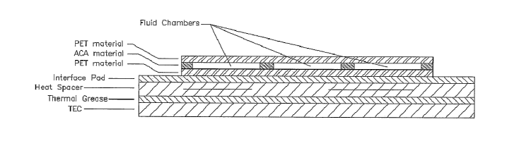
Figure 29 is a cross section of a microfluidic card using a TEC for
thermocycling in accordance with principles of the present invention as
discussed above. In Figure 29, multiple amplification reservoirs or fluid
chambers are simultaneously cycled by the TEC. The amplification reservoirs
are contained between layers of PET material and an ACA (adhesive carrier
adhesive) material to provide a disposable microfluidic card.
As further illustrated in Figure 29, a heat spacer or heat spreader
may be used between the TEC and the amplification reservoirs in order to
provide a more uniform heat across the TEC surface. The heat spreader will
ultimately be determined by the thermal profile of the TEC, but one exemplary
heat spreader is a layer of PTFE between layers of copper, however those
skilled in the art will understand that many variations of heat spreaders are
acceptable.
The interface pad illustrated in Figure 29 is a thermal pad to more
efficiently transfer heat to the microfluidic card. Likewise, the thermal
grease
22
CA 02528208 2005-12-05
WO 2004/108287 PCT/US2004/017943
between the TEC and the heat spreader or spacer is know to those in the art to
further enhance heat transfer.
Exemplary Amplification Methods and Temperature Cycles
The following temperature profiles have been achieved on
microfluidic cards using methods and apparatuses of the present invention.
A. Polymerase Chain Reaction (PCR) Temperature Profile
100
8O
0
6
a
40
0
10
20
time
Primary goals:
1 ) Consistent
15 2) Adjustable and accurate temperature for anneal step (lowest T)
3) Adjustable hold time for anneal step
4) Adjustable hold time at extension step (72 C)
5) Do not exceed 95 C (prevents denaturing of enzyme)
6) Rapid
B. Nucleic Acid Seguence Based Analysis (NASBA) Temperature Profile
~o -
__.
60
50
s
40
c
.
E
20
0
20
60
80
100
120
time
23
CA 02528208 2005-12-05
WO 2004/108287 PCT/US2004/017943
Primary goals:
1 ) Stable 40 C temperature (> 42 C denatures enzyme). +/- 1.0 C.
2) Adjustable hold times for 65 C and' 40 C. 90 minutes maximum for 40 C.
2) 65 C or greater is OK.
3) 2 to 5 minute hold at 65 C is standard, but shorter may be OK (unknown).
4) Consistent time to 40 C after 65 C (for programmed enzyme addition)
5) Shorter is better, but 1-2 minutes for cooling from 65 to 40 C is OK
- current block heaters used with DART take ~10 minutes
- current thermal cyclers take ~1 minute
C Reverse Transcriptase (rt) Temperature Profile
so --_.__ .._ . _ ..
70
L
60
~a
d
50
40
30
0 20 40 60 80 100
time
Primary goals:
1) Stable 47 C temperature with zero or minimal overshoot.
20 2) Adjustable hold time for 47 C. 60 minutes maximum.
3) Rapid rise to 75C or higher for 10 minutes.
D Loop Mediated Amplification (LAMP) Temperature Profile
70 --
60
0
c
5
L
40
c
.
E
0
3
20
0 20 40 60 80
time
24
CA 02528208 2005-12-05
WO 2004/108287 PCT/US2004/017943
Primary Goals:
1 ) Stable 62 C with minimal overshoot
2) Adjustable hold time for 62 C. 60 minutes maximum.
Conclusion
The above description of illustrated embodiments of the invention
is not intended to be exhaustive or to limit the invention to the precise form
discloses. While specific embodiments of, and examples for, the invention are
described herein for illustrative purposes, various equivalent modifications
are
possible within the scope of the invention, as those skilled in the relevant
art will
recognize. The teachings provided herein of the invention can be applied to
other microfluidic devices, not necessarily the PCR and rtPCR cards described
above.
From the foregoing it will be appreciated that, although specific
embodiments of the invention have been described herein for purposes of
illustration, various modifications may be made without deviating from the
spirit
and scope of the invention. Accordingly, the invention is not limited except
as
by the appended claims.