Note: Descriptions are shown in the official language in which they were submitted.
CA 02528247 2005-12-05
WO 2004/111128 PCT/US2004/017697
FLEXIBLE BAKEWARE
1. Field of the Invention
This invention relates generally to flexible bakeware and in particular to an
improved flexible bakeware container that is made from a novel compound and
includes a carrier for assisting a user in carrying the bakeware container.
2. Description of Related Art
Flexible bakeware is typically made from a silicone rubber formulation. The
silicone composition prevents strong odors from being transferred to the food,
yet
provides a tough, temperature resistant material that, due to its flexibility,
allows food
to be removed more easily than with traditional bakeware. One downside to
using a
silicone composition for bakeware is that the flexibility of the material
makes it
difficult to handle. The bakeware cannot be easily carried with one hand.
Instead, it
must be fully supported under its bottom surface, and most users simply place
a
metal cooking sheet or other rigid pan underneath the bakeware to transfer the
bakeware to and from the oven. This solution is impractical because the
presence of
a solid sheet of metal underneath the flexible bakeware can provide
inconsistent
(and uneven) baking of the food product contained by the bakeware. More
specifically, the sides and top of the bakeware experience convective heating
from
the hot air within the oven. The bottom of the bakeware experiences conductive
heating since it is in direct contact with the solid metal cooking sheet. This
difference
in heating methods can cause uneven cooking of the food product. The
inconvenience of using a cooking sheet to transport flexible bakeware is also
a
drawback.
A need therefore exists for an apparatus that could be used in conjunction
with a flexible baking container that would permit easy transport of the
baking
container. A need further exists for an apparatus that could be incorporated
into the
flexible baking container so that together the device and bakeware are a self
contained unit. Still another need exists for an apparatus that can be readily
removed from the baking container periodically for cleaning.
Flexible bakeware also experiences release problems with certain foods.
Compared to conventional non-flexible bakeware, it is often easier to remove
foods
from flexible bakeware because the basin containing the food product can be
turned
inside out. However, with certain foods such as muffins, cakes, or breads,
residue
-1-
CA 02528247 2005-12-05
WO 2004/111128 PCT/US2004/017697
from the foods may remain stuck to the flexible bakeware, thereby causing an
uneven and unattractive outer surface on the food product following removal
from
the bakeware.
One solution to the problem of food release is to pre-lubricate a baking
container with cooking spray, cooking oil, or flour. While this can prevent
food from
sticking to baking containers, the solution is undesirable because it involves
additional steps in cooking the food (i.e. the step of pre-lubricating) and
requires
additional cooking supplies (i.e. the spray, oil, or flour). Another drawback
is that the
use of oils or flour can alter the taste and texture of the baked food
product.
A need therefore exists for flexible bakeware that has improved food release
qualities as compared to currently used flexible bakeware. A need further
exists for
a compound that can be easily and inexpensively manufactured into flexible
bakeware. The compound should be non-toxic and should not impart an odor or
taste to food products prepared in the bakeware.
BRIEF SUMMARY OF THE INVENTION
The problems presented by existing flexible bakeware are solved by the
present invention. A flexible bakeware compound is provided that includes a
methyl
vinyl silicone polymer from about 40 to 70 weight percent, a filler from about
5 to 50
weight percent, a curing agent from about 0.1 to 5 weight percent, and
polytetrafluoroethylene from about 0.1 to 15 weight percent. In a preferred
embodiment, the polytetrafluoroethylene is present in an amount of about 6
percent.
The filler is preferably ground quartz, and the curing agent is preferably
chloro
platanic acid.
Also provided by the present invention is a flexible bakeware compound
having a methyl vinyl silicone polymer of about 61 weight percent, a filler of
about
28.5 weight percent, a curing agent of about 0.57 weight percent, and
polytetrafluoroethylene of about 6 weight percent. Preferably, the filler is
ground
quartz, and the curing agent is chloro platanic acid. The flexible bakeware
compound may also include high vinyl silicone gum from about 1.1 weight
percent, a
pigment from about 1.1 weight percent, zinc stearate from about 0.14 weight
percent, silicone hydride from about 1.7 weight percent, and ethynl
cyclohexanol
from about 0.01 weight percent.
A method for baking a food product is also provided by the present invention.
The method includes the step of providing a flexible baking container formed
from an
-2
CA 02528247 2005-12-05
WO 2004/111128 PCT/US2004/017697
addition-cured silicone polymer having polytetrafluoroethylene from about 0.1
to 15
weight percent. A food product is deposited in the baking container, and the
container is placed in an oven at a baking temperature for a predetermined
time until
the food product is baked. The food product is then removed from the baking
container.
The invention further provides an elastomeric baking container having a basin
and shoulder surrounding the basin. A receiving channel is disposed in the
shoulder
of the baking container and receives a carrier. The placement of the carrier
within
the receiving channel provides additional rigidity to the shoulder, which
makes the
baking container easier to carry.
A method of baking a food product is provided by the present invention and
includes the steps of providing a flexible baking container having a basin and
a
shoulder. A receiving channel is disposed in the shoulder, and a carrier is
received
by the receiving channel. A food product is deposited in the baking container,
and
the flexible baking container is carried to an oven by gripping the carrier,
or some
portion of the carrier along with the shoulder of the baking container. The
baking
container is placed in an oven at a baking temperature for a predetermined
amount
of time until the food product is baked.
The carrier of the present invention can be provided in many different shapes
and sizes. The shape of the carrier will generally match the shape of the
receiving
channel. For example, the carrier can be made from a rod with a circular cross
section. The receiving channel in this case would have a circular cross
section. In
some instances, a portion of the carrier may extend out of the shoulder of the
bakeware as a handle. The presence of handles is not required but may make the
bakeware easier to carry.
Another carrier that may be used is one for a plurality of muffin cups (i.e.
bakeware, or baking containers). This carrier is preferably a flat, rigid
plate with a
plurality of apertures. A flexible muffin cup is placed within each aperture
so that a
receiving channel on a shoulder of the muffin cup receives a portion of the
flat
carrier. The receiving channel may even have a depression for receiving a lip
formed on an edge of the carrier's aperture. When the depression engages the
lip of
the carrier, the muffin cup is more securely attached to the carrier and less
likely to
become inadvertently disengaged from the carrier.
-3-
CA 02528247 2005-12-05
WO 2004/111128 PCT/US2004/017697
Other objects, features, and advantages of the present invention will become
apparent with reference to the drawings and detailed description that follow.
BRIEF DESCRIPTION OF THE DRAWINGS
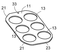
FIG. 1 depicts a perspective view of a flexible bakeware carrier for a
plurality
of flexible muffin cups according to a preferred embodiment of the present
invention;
FIG. 2 illustrates a top view of the flexible bakeware carrier of FIG. 1;
FIG. 3 depicts a cross-sectional front view of the flexible bakeware carrier
of
FIG. 2 taken at III-III;
FIG. 4 illustrates an enlarged front view of the of flexible bakeware carrier
of
FIG. 3 taken at Detail IV;
FIG. 5 depicts a cross-sectional front view of a flexible muffin cup according
to
a preferred embodiment of the present invention, the muffin cup designed for
use
with the flexible bakeware carrier of FIG. 1;
FIG. 6 illustrates an enlarged front view of the flexible muffin cup of FIG. 5
taken at Detail VI;
FIG. 7 depicts an enlarged front view of a flexible muffin cup according to an
alternative embodiment of the present invention, the view being taken at an
area of
the flexible muffin cup similar to that shown in FIG. 6;
FIG. 8 illustrates a perspective view of a flexible bakeware carrier for a
plurality of flexible muffin cups according to an alternative embodiment of
the present
invention;
FIG. 9 depicts a top view of a rectangular, flexible bakeware according to a
preferred embodiment of the present invention;
FIG. 10 illustrates a cross-sectional front view of the rectangular, flexible
bakeware of FIG. 9 taken at X-X;
FIG. 11 depicts an enlarged front view of the rectangular, flexible bakeware
of
FIG. 10 taken at Detail XI;
FIG. 12 illustrates a cross-sectional top view of the rectangular, flexible
bakeware of FIG. 10 taken at XII-XII;
FIG. 13 depicts a top view of a flexible bakeware carrier according to a
preferred embodiment of the preferred invention, the carrier designed for use
with
the flexible bakeware of FIG. 9;
FIG. 14 illustrates a top view of a flexible bakeware carrier according to an
alternative embodiment of the present invention;
-4-
CA 02528247 2005-12-05
WO 2004/111128 PCT/US2004/017697
FIG. 15 depicts a top view of a rectangular, flexible bakeware according to an
alternative embodiment of the present invention, the bakeware designed for use
with
the carrier of FIG. 14;
FIG. 16 illustrates a cross-sectional front view of the rectangular, flexible
bakeware of FIG. 15 taken at XVI-XVI;
FIG. 17 depicts an enlarged front view of the rectangular, flexible bakeware
of
FIG. 16 taken at Detail XVII;
FIG. 18 illustrates a top view of a round, flexible bakeware according to a
preferred embodiment of the present invention;
FIG. 19 depicts a cross-sectional front view of the round, flexible bakeware
of
FIG. 18 taken at XIX-XIX;
FIG. 20 illustrates an enlarged front view of the round, flexible bakeware of
FIG. 19 taken at Detail XX;
FIG. 21 depicts a cross-sectional top view of the round, flexible bakeware of
FIG. 19 taken at XXI-XXI;
FIG. 22 illustrates a top view of a flexible bakeware carrier according to a
preferred embodiment of the present invention, the carrier designed for use
with the
round, flexible bakeware of FIG. 18;
FIG. 23 depicts a top view of a flexible bakeware carrier according to an
alternative embodiment of the present invention;
FIG. 24 illustrates a perspective view of a round, flexible bakeware according
to an alternative embodiment of the present invention, the flexible bakeware
designed for use with the flexible bakeware carrier of FIG. 23;
FIG. 25 depicts a cross-sectional front view of the round, flexible bakeware
of
FIG. 24; and
FIG. 26 illustrates an enlarged front view of the round, flexible bakeware of
FIG. 25 taken at Detail XVI.
FIG. 27 depicts a flow chart of a method of baking a food product according to
the present invention.
DETAILED DESCRIPTION OF THE PREFERRED EMBODIMENT
In the following detailed description of the preferred embodiments, reference
is made to the accompanying drawings which form a part hereof, and in which is
shown by way of illustration specific preferred embodiments in which the
invention
may be practiced. These embodiments are described in sufficient detail to
enable
-5
CA 02528247 2005-12-05
WO 2004/111128 PCT/US2004/017697
those skilled in the art to practice the invention, and it is understood that
other
embodiments may be utilized and that logical mechanical, structural, and
chemical
changes may be made without departing from the spirit or scope of the
invention. To
avoid detail not necessary to enable those skilled in the art to practice the
invention,
. the description may omit certain information known to those skilled in the
art. The
following detailed description is, therefore, not to be taken in a limiting
sense, and
the scope of the present invention is defined only by the appended claims.
In describing the present invention, the term "elastomer" refers generally to
a
polymeric material that has rubberlike properties. More specifically, most
elastomers
have elongation rates greater than 100% and a significant amount of
resilience. The
resilience of a material refers to the material's ability to recover from an
elastic
deformation. Examples of elastomers could include, but are not limited to,
natural
rubbers, polyisoprene, styrene butadiene rubber, chloroprene rubber,
polybutadiene,
nitrite rubber, butyl rubber, ethylene propylene rubber, ethylene propylene
diene
monomer, chlorosulfonated polyethylene, polysulfide rubber, polyurethane, and
silicones.
The term "flexible" refers to an object or material that is able to bent or
flexed.
The use of the term flexible in connection with a material or bakeware of the
present
invention generally refers to a material or bakeware made from an elastomer or
other
material that allows the container portion, or basin, of the bakeware to be at
least
partially turned inside out without plastic deformation of the material.
Referring to FIGS. 1-4, a carrier 11 according to one embodiment of the
present invention is illustrated. The carrier apparatus 11 is used in
conjunction with
flexible muffin cups. Carrier 11 is a substantially rigid, flat plate made
from either
metal or temperature-resistant plastic. Carrier 11 includes a plurality of
apertures 13,
each adapted to receive a flexible muffin cup. Carrier 11 is preferably
rectangular in
shape with a chamfer 21 at each corner of the carrier. Carrier 11 is
preferably made
from brushed stainless steel, and all perimeter edges 23 of the carrier 11
have been
rolled to form a perimeter lip 25 (see FIG. 4). Similarly, the edges 29 of
apertures 13
have also been rolled to form perimeter lips 31. By rolling the exposed edges
23, 25
of the carrier 11, the sharpness of the edges is eliminated. Carrier 11 also
includes
a hanger hole 33 at one end of the carrier 11 for allowing the carrier to be
hung on a
kitchen wall.
-6-
CA 02528247 2005-12-05
WO 2004/111128 PCT/US2004/017697
Referring to FIGS. 5 and 6, a flexible baking container, or muffin cup 41,
according to a preferred embodiment of the present invention includes a basin
43
formed by a substantially cylindrical, tapering wall 44 integrally connected
to a floor
46. One end of wall 44 terminates in a shoulder 45, the shoulder having a
receiving
channel 47. Receiving channel 47 preferably includes a depression 49 that is
adapted to receive the perimeter lip 31 of carrier 11. In order to obtain
optimum
flexibility and release, the wall thickness of each muffin cup should be
between 0.020
and 0.100 inches. Preferably, the wall thickness is 0.050-0.075 inches.
In operation, each aperture 13 on carrier 11 receives a muffin cup 41 such
that a portion of the carrier 11 fits within receiving channel 47. When
installed, the
perimeter lip 31 of the carrier 11 is firmly seated in the depression 49 of
the receiving
channel 47. The engagement of the lip 31 by depression 49 more firmly secures
the
muffin cups 41 on the carrier and prevents accidental or inadvertent
disengagement
of the muffin cups 41 and the carrier 11.
The carrier 11 provides rigidity to the muffin cups 41 in an area around each
shoulder 45 and allows a user to carry the flexible muffin cups 15 with one
hand.
The flexibility of the muffin cups 41 allows a user to easily remove the cups
from the
carrier 11. The removal of the muffin cups could aid a user in removing food
from
the muffin cup, although it is not necessary to remove the cup to effectuate
release
of a food product. The ease with which the muffin cups can be removed also
promotes the use of muffin cups having different shapes and depths. For
example, a
muffin cup having a basin 17 that is heart shaped may be used to bake heart-
shaped
muffins on Valentine's Day. Other possible shapes include without limitation
stars,
clover leaves, squares, triangles, and diamonds.
Referring to FIGS. 7 and 8, a muffin cup 51 and a carrier 61 according to
alternative embodiments of the present invention are illustrated. Muffin cup
51 is
similar to muffin cup 41 and includes a basin 53 formed by a substantially
cylindrical,
tapering wall 54 connected to a floor (not shown) at one end and terminating
in a
shoulder 55 at another end. Shoulder 55 includes a receiving channel 57, but
unlike
muffin cup 41, does not include a depression 49.
Muffin cup 51 is designed for use with a carrier such as carrier 11, or
preferably carrier 61. Referring to FIG. 8, carrier 61 is a rectangular, flat
plate made
from metal or temperature-resistant plastic. Carrier 61 includes a plurality
of
apertures 63 for receiving muffin cups 51. The primary difference between
carrier 61
-7
CA 02528247 2005-12-05
WO 2004/111128 PCT/US2004/017697
and carrier 11 (FIGS. 1-4) is that carrier 61 does not include rolled lips at
perimeter
edges 65 or edges 67 of the apertures. The lack of a lip at edges 67 allows
the
carrier 11 to better mate with muffin cup 61, which includes no depression in
receiving channel 57.
Referring to FIGS. 9-12, a rectangular, flexible baking container 111
according to a preferred embodiment of the present invention includes a basin
112
formed by a pair of major walls 113 and a pair of minor walls 114, the walls
113, 114
being integrally joined to each other and at one end to a floor 115. A
shoulder 117 is
formed at an end of the walls 113, 114 opposite floor 115, the shoulder 117
extending completely around the perimeter of the baking container 111.
Shoulder
117 includes an outer surface 121, an inner surface 122, an upper surface 123,
and
a lower surface 125. A receiving channel 131 having a circular cross section
is
disposed in the shoulder 117 with an entry slot 135 positioned between the
lower
surface 125 of the shoulder 117 and the receiving channel 131. In the
preferred
embodiment, the entry slot 135 is disposed adjacent the lower surface 125 (as
shown in FIG. 11), but it is conceivable that the entry slot 135 could be
disposed
adjacent the outer surface 121, the inner surface 122, or the upper surface
123.
Referring more specifically to FIG. 12, the receiving channel 131 and entry
slot 135 are not continuous around the entire perimeter of the flexible baking
container 111. Instead, the receiving channel 131 includes a central portion
141 that
runs continuously in the shoulder 117 adjacent each major wall 113. As the
receiving channel 131 approaches corner portions 151 of the shoulder 117, a
turning
portion 143 of the receiving channel 131 follows the shoulder around the
corner
portion 151. An exit portion 145 of the receiving channel then turns in a
direction
opposite minor walls 114 and exits the outer surface 121 of the shoulder 117.
Because of the discontinuous nature of the receiving channel 131, the baking
container 111 actually contains a pair of receiving channels 131 as
illustrated in FIG.
12.
The preferred location of the central portion 141 of the receiving channel 131
is in the shoulder 117 adjacent each major wall 113. This configuration
provides the
most support for the carrier that is received by the receiving channel 131
(explained
in more detail below). However, a person of ordinary skill in the art will
recognize
that the central portion 141 of each receiving channel 131 could instead be
located in
the shoulder adjacent each minor wall 114.
_g_
CA 02528247 2005-12-05
WO 2004/111128 PCT/US2004/017697
Referring to FIG. 13, a carrier 161 according to a preferred embodiment of the
present invention is used in conjunction with flexible baking container 111.
Carrier
161 is formed by a substantially rigid rod having a substantially circular
cross section
and made of metal or temperature-resistant plastic. Preferably, the material
composition of the rod is 304 stainless steel. Carrier 161 includes a pair of
central
stays 165 that are substantially parallel to one another and are joined at
each end to
an arcuate stay 167. An end of each arcuate stay 167 is joined to one end of a
handle 169. Together, the pair of central stays 165, the four arcuate stays
167, and
the pair of handles 169 form a closed loop. The shape and length of the
central
stays and the arcuate stays closely approximate those of central portion 141
and
turning portion 143 of the receiving channel 131. Preferably, the central
stays 165,
arcuate stays 167, and handles 169 are welded together from stainless steel
rods,
but the carrier 161 could be formed using any other suitable manufacturing
techniques know to those of ordinary skill in the art.
In operation, carrier 161 is received by flexible baking container 111 by
inserting the centrals stays 165 and arcuate stays 167 through the entry slot
135 of
the baking container 111 and into the receiving channel 131. The flexible
properties
of the baking_ container 111 allow the shoulder 117 to bend such that the
entry slot
135 is temporarily enlarged to accommodate the carrier 161 as it passes
through the
entry slot 135 and into the receiving channel 131. After the central stays 165
are
positioned within the central portions 141 of the receiving channels 131 and
the
arcuate stays 167 are positioned within the turning portions 143 of the
receiving
channels 131, the shoulder 117 elastically returns to its original shape. With
the
shoulder in a "non-deformed" shape, the entry slot 135 is again smaller than
the
receiving channel 131, which secures carrier 161 within the receiving channel
131.
With the carrier 161 installed in the receiving channel 131, a portion of the
handle 169 is disposed within the exit portion 145 of the receiving channel,
but the
majority of the handle 169 is located outside the walls of the flexible baking
container
111. Handle 169 enables a user of the flexible baking container 111 to easily
lift and
carry the baking container 111 by holding either or both handles on the that
portion
of the handle 169 that protrudes from the baking container.
The carrier 161 provides rigidity to the flexible baking container 111 in an
area
around each shoulder 117 and allows a user to more easily lift and carry the
baking
container 111. The flexibility of the baking container 111 allows a user to
easily
_g_
CA 02528247 2005-12-05
WO 2004/111128 PCT/US2004/017697
remove the carrier 161 from the receiving channel 131 of the baking container
111.
The removal of the carrier 161 could aid a user in removing food from the
baking
container 111, although it is not necessary to remove the carrier 161 to
effectuate
release of a food product.
Referring to FIGS. 14-17, a rectangular, flexible baking container 171
according to an alternative embodiment of the present invention includes a
basin 172
formed by a pair of major walls 173 and a pair of minor walls 174, the walls
173, 174
being integrally joined to each other and at one end to a floor 175. A
shoulder 177 is
formed at an end of the walls 173, 174 opposite floor 175, the shoulder 177
extending completely around the perimeter of the baking container 171.
Shoulder
177 includes an outer surface 181, an inner surface 182, an upper surface 183,
and
a lower surface 185. A receiving channel 191 having a rectangular cross
section is
disposed in the shoulder 177 with an entry slot 195 positioned between the
lower
surface 185 of the shoulder 177 and the receiving channel 191. In the
preferred
embodiment, the entry slot 195 is disposed adjacent the lower surface 185 (as
shown in FIG. 17), but it is conceivable that the entry slot 195 could be
disposed
adjacent the outer surface 181, the inner surface 182, or the upper surface
183.
The receiving channel 191 and entry slot 195 are preferably continuous
around the entire perimeter of the flexible baking container 171. However, it
is
conceivable that a discontinuous receiving channel 191 and entry slot 195
could be
used similar to those of baking container 111 (see FIG. 12).
Referring more specifically to FIG. 14, a carrier 201 according to an
alternative embodiment of the present invention is used in conjunction with
flexible
baking container 171. Carrier 201 is a rectangular plate having a central
aperture
203 and is made of metal or temperature-resistant plastic. The shape and size
of
carrier 201 closely approximate those of the receiving channel 191 of baking
container 171.
In operation, carrier 201 is received by flexible baking container 171 by
inserting the carrier 201 through the entry slot 195 of the baking container
171 and
into the receiving channel 191. The flexible properties of the baking
container 171
allow the shoulder 177 to bend such that the entry slot 195 is temporarily
enlarged or
deformed to accommodate the carrier 201 as it passes through the entry slot
195
and into the receiving channel 191. After the carrier 201 is positioned within
the
receiving channel 191, the shoulder 177 elastically returns to its original
shape. With
-10
CA 02528247 2005-12-05
WO 2004/111128 PCT/US2004/017697
the shoulder 177 in a "non-deformed" shape, the entry slot 195 is again
smaller than
the receiving channel 191, which secures carrier 201 within the receiving
channel
191.
Carrier 201 provides rigidity to the flexible baking container 171 in an area
around shoulder 177 and allows a user to more easily lift and carry the baking
container 171. The flexibility of the baking container 171 allows a user to
easily
remove the carrier 201 from the receiving channel 191 of the baking container
171.
The removal of the carrier 201 could aid a user in removing food from the
baking
container, although it is not necessary to remove the carrier 201 to
effectuate the
release of a food product.
Referring to FIGS. 18-21, a round, flexible baking container 211 according to
a preferred embodiment of the present invention includes a basin 212 formed by
a
substantially cylindrical, tapering wall 213 that is integrally joined at one
end to a
floor 215. A shoulder 217 is formed at an end of the wall 213 opposite floor
215, the
shoulder 217 extending completely around the perimeter of the baking container
211. Shoulder 217 includes an outer surface 221, an inner surface 222, an
upper
surface 223, and a lower surface 225. A receiving channel 231 having a
circular
cross section is disposed in the shoulder 217 with an entry slot 235
positioned
between the lower surface 225 of the shoulder 217 and the receiving channel
231.
' In the preferred embodiment, the entry slot 235 is disposed adjacent the
lower
surface 225 (as shown in FIG. 20), but it is conceivable that the entry slot
235 could
be disposed adjacent the outer surface 221, the inner surface 222, or the
upper
surface 223.
Referring more specifically to FIG. 21, the receiving channel 231 and entry
slot 235 are not continuous around the entire perimeter of the flexible baking
container 211. Instead, the receiving channel 231 includes an arcuate portion
241
that is continuous in a portion of the shoulder 217 and subtends an angle that
is
preferably greater than or equal to 90 degrees. An exit portion 245 is of the
receiving channel 231 is located at both ends of the arcuate portion 241. Exit
portion
245 turns in a direction away from wall 213 and exits the outer surface 221 of
the
shoulder 217. Because of the discontinuous nature of the receiving channel
231, the
baking container 211 actually contains a pair of receiving channels 231
diametrically
opposed on the shoulder 217 (see FIG. 21).
-11-
CA 02528247 2005-12-05
WO 2004/111128 PCT/US2004/017697
Referring to FIG. 22, a carrier 261 according to a preferred embodiment of the
present invention is used in conjunction with flexible baking container 211.
Carrier
261 is formed by a substantially rigid rod having a substantially circular
cross section
and made of metal or temperature-resistant plastic. Preferably, the material
composition of the rod is 304 stainless steel. Carrier 261 includes a pair of
central
stays 265 that are joined at each end to a handle 269. Together, the pair of
central
stays 265 and the pair of handles 269 form a closed loop. The shape and length
of
the central stays 265 closely approximate those of arcuate portion 241 of the
receiving channel 231. Preferably, the central stays 265 and handles 269 are
welded together from stainless steel rods, but the carrier 261 could be formed
using
any other suitable manufacturing techniques know to those of ordinary skill in
the art.
In operation, carrier 261 is received by flexible baking container 211 by
inserting the centrals stays 265 and a portion of the handles 269 through the
entry
slot 235 of the baking container 211 and into the receiving channel 231. The
flexible
properties of the baking container 211 allow the shoulder 217 to deform such
that the
entry slot 235 is temporarily enlarged to accommodate the carrier 261 as it
passes
through the entry slot 235 and into the receiving channel 231. After the
central stays
265 are positioned within the arcuate portions 241 of the receiving channels
231, the
shoulder 217 elastically returns to its original shape. With the shoulder in a
"non-
deformed" shape, the entry slot 235 is again smaller than the receiving
channel 231,
which secures carrier 261 within the receiving channel 231.
With the carrier 261 installed in the receiving channel 231, a portion of the
handle 269 is disposed within the exit portion 245 of the receiving channel,
but the
majority of the handle 269 is located outside the wall of the flexible baking
container
211. Handle 269 enables a user of the flexible baking container 211 to easily
lift and
carry the baking container 211 by holding either or both handles on the
portion of the
handle 269 that protrudes from the baking container.
The carrier 261 provides rigidity to the flexible baking container 211 in an
area
around each shoulder 217 and allows a user to more easily lift and carry the
baking
container 211. The flexibility of the baking container 211 allows a user to
easily
remove the carrier 261 from the receiving channel 231 of the baking container
211.
The removal of the carrier 261 could aid a user in removing food from the
baking
container 211, although it is not necessary to remove the carrier 261 to
effectuate
the release of a food product.
-12-
CA 02528247 2005-12-05
WO 2004/111128 PCT/US2004/017697
Referring to FIGS. 23-26, a round, flexible baking container 271 according to
an alternative embodiment of the present invention includes a basin 272 formed
by a
substantially cylindrical, tapering wall 273 that is integrally joined at one
end to a
floor 275. A shoulder 277 is formed at an end of the wall 273 opposite floor
275, the
' shoulder 277 extending completely around the perimeter of the baking
container
271. Shoulder 277 includes an outer surface 281, an inner surface 282, an
upper
surface 283, and a lower surface 285. A receiving channel 291 having a
rectangular
cross section is disposed in the shoulder 277 with an entry slot 295
positioned
between the lower surface 285 of the shoulder 277 and the receiving channel
291.
In the preferred embodiment, the entry slot 295 is disposed adjacent the lower
surface 285 (as shown in FIG. 26), but it is conceivable that the entry slot
295 could
be disposed adjacent the outer surface 281, the inner surface 282, or the
upper
surface 283.
The receiving channel 291 and entry slot 295 are preferably continuous
around the entire perimeter of the flexible baking container 271. However, it
is
conceivable that a discontinuous receiving channel 291 and entry slot 295
could be
used similar to that of baking container 211 (see FIG. 21 ).
Referring more specifically to FIG. 23, a carrier 301 according to an
alternative embodiment of the present invention is used in conjunction with
flexible
baking container 271. Carrier 301 is a ring-shaped plate having a central
aperture
303 and is made of metal or temperature-resistant plastic. The shape and size
of
carrier 301 closely approximate those of the receiving channel 291 of baking
container 271.
In operation, carrier 301 is received by flexible baking container 271 by
inserting the carrier 301 through the entry slot 295 of the baking container
271 and
' into the receiving channel 291. The flexible properties of the baking
container 271
allow the shoulder 277 to bend such that the entry slot 295 is temporarily
enlarged or
deformed to accommodate the carrier 301 as it passes through the entry slot
295
and into the receiving channel 291. After the carrier 301 is positioned within
the
receiving channel 291, the shoulder 277 elastically returns to its original
shape. With
the shoulder 277 in a "non-deformed" shape, the entry slot 295 is again
smaller than
the receiving channel 291, which secures carrier 301 within the receiving
channel
291.
-13-
CA 02528247 2005-12-05
WO 2004/111128 PCT/US2004/017697
Carrier 301 provides rigidity to the flexible baking container 271 in an area
around shoulder 277 and allows a user to more easily lift and carry the baking
- container 271. The flexibility of the baking container 271 allows a user to
easily
remove the carrier 301 from the receiving channel 291 of the baking container
271.
The removal of the carrier 301 could aid a user in removing food from the
baking
container, although it is not necessary to remove the carrier 301 to
effectuate the
release of a food product.
The flexible bakeware (i.e. the muffin cups 41, 51, the rectangular baking
containers 111, 171, and the round baking containers 211, 271 ) composition of
the
present invention is preferably made from an addition-cured silicone material.
The
following table illustrates the preferred amounts and potential ranges for the
flexible
bakeware composition of the present invention:
i
Preferred Range
ompound Amount (Weight
(Weight %)
%)
Polydimethylvinylsiloxane/Silica60.88 40-70
High Vinyl Silicone Gum 1.1 0.5-10
Ground Quartz (filler) 28.5 5-50
Polytetrafluoroethylene 6.0 0.1-15
Black Iron Oxide (pigment) 1.1 ~ 0.1-5
Zinc Stearate (internal mold0.14 r 0.1-5
release)
Silicon Hydride 1.7 0.1-25
Chloro Platanic Acid (cross-0.57 0.1-5
linking agent)
Ethynl Cyclohexanol (inhibitor)0.01 0.05-5
-14-
CA 02528247 2005-12-05
WO 2004/111128 PCT/US2004/017697
The flexible bakeware compound preferably contains 0.1 to 15 weight percent
of polytetrafluoroethylene (PTFE). Testing of silicone bakeware with these
amounts
of PTFE has revealed superior release properties compared to silicone bakeware
without PTFE. Several different compounds were tested by baking foods in the
bakeware and then determining the amount of food residue remaining in the
bakeware following the removal of the baked goods. Clearly, less food residue
in the
bakeware indicates better release properties. Silicone bakeware without PTFE
required the use of a non-stick spray or flour to eliminate food residue
following
baking. Although silicone bakeware having PTFE ranging from 0.1 to 15 weight
percent exhibited improved release properties without the use of a non-stick
spray or
flour, the optimum composition was determined to include six (6) weight
percent
PTFE.
The preferred particle size of PTFE used with the present invention is
approximately 6 pm (i.e. microns), with a maximum particle size of 25 pm.
While
larger particle sizes of PTFE can also impart improved release properties to
the
bakeware, the plasticity of the resulting compound is sometimes increased to
an
extent that extrusion and molding of the compound is difficult or impossible.
An
example of PTFE commonly used in preparing the flexible bakeware compound of
the present invention is Polymist F-5A, which can be obtained from Ausimont
USA.
Polymist F-5A contains particles of a relatively small size, typically at or
below 6 pm.
The compounding of PTFE in the formulation of the present invention results
in the migration of PTFE to the surface of the flexible bakeware. The presence
of
the PTFE at or near the surface at least partially results in the superior
release
properties of the bakeware. Another advantage provided by the PTFE is that it
does
not impart an odor or taste to food products baked in the bakeware.
The flexible bakeware compound is preferably combined with a cross-linking
" agent to insure that the bonds of the compound properly form. The cross
linking
agent may be a catalyst, such as platinum, or a curing agent such as peroxide.
A
platinum catalyst (i.e. chloro platanic acid) is preferably used in
conjunction with
silicon hydride to insure that the proper bonds form between the platinum and
the
silicone compound. If a curing agent, such as peroxide, were used, silicone
hydride
would not be required. However, peroxide is not preferred because it generally
imparts an unpleasant odor and smell to foods baked in the bakeware. Other
catalysts, including but not limited to cesium, palladium, rhodium, iron,
cobalt, nickel,
-15
CA 02528247 2005-12-05
WO 2004/111128 PCT/US2004/017697
rubidium, osmium, or iridium, could be used in place of platinum. However,
these
substances are generally not favored because they are either more expensive
(e.g.
palladium) or have problems associated with contamination (e.g. iron).
The preferred filler for the bakeware compound is ground quartz in an amount
of about 28.5 weight percent; however, filler in an amount of 5-50 weight
percent
could be used. Alternative fillers include silica, calcium, or any other
mineral.
The bakeware compound preferably contains black iron oxide in an amount of
1.1 weight percent, which gives the finished bakeware a black color. Depending
on
the desired color for the bakeware, many different pigments could be used, and
the
amount of pigment used could also be varied to alter the color. Preferably,
the
weight range of the pigment is between 0.1 and 5 weight percent.
High vinyl silicone gum is preferably added to the compound in an amount of
about 1.1 weight percent; however, the compound could include high vinyl
silicone
gum in any amount between about 0.5 and 10 weight percent. The vinyl component
of high vinyl silicone gum is preferably 8-20 percent pendant vinyl with a
preferred
amount of 14 percent.
The novel composition of the present invention preferably has a specific
gravity of about 1.12 to 1.64.
Each item of flexible bakeware is preferably injection, compression, or
transfer
- molded. To further enhance the release properties of the bakeware, a molding
tool
having a finish between A1 and B2 is used to form the bakeware, with the
preferred
finish being A2. Molding finishes of this type are known standards within the
molding
industry.
Referring to FIG. 27, a method for baking a food product 309 according to the
present invention includes, in step 311, providing a flexible baking container
formed
from an addition-cured silicone polymer having polytetrafluoroethylene in
amount of
about 0.1 to 15 weight percent. In step 313 a carrier adapted to be received
by a
receiving channel in the flexible baking container is provided. A user
deposits a food
product in the baking container at step 315, and the baking container is
placed in an
oven at a baking temperature for a predetermined time until the food product
is
baked at step 317. The baked food product is removed from the baking container
at
step 319.
Several variations of the method illustrated in FIG. 27 are possible. First,
the
use of the carrier is not required if the baking container is made from the
novel
-16
CA 02528247 2005-12-05
WO 2004/111128 PCT/US2004/017697
flexible bakeware compound of the present invention. Alternatively, the
carrier may
be used with a traditional flexible baking container instead of one
incorporating the
flexible bakeware compound. In either situation, all of the features and
advantages
explained previously in connection with the flexible bakeware compound and
carrier
are applicable to the bakeware used with the method.
It should be apparent that although the flexible bakeware of the present
invention has been described in terms of a round muffin cup, a rectangular
baking
container, and a round baking container, any size or shape of flexible
bakeware
could be included within the scope of the present invention. Similarly, the
carrier
could be provided in many different shapes or sizes, and may include single or
multiple handles that extend outward from the bakeware. Alternatively, the
carrier
may have no handles at all. The receiving channel shapes and sizes that are
formed
in each piece of flexible bakeware could also vary as long as the bakeware is
securely attached to the carrier member and will not become disengaged from
the
carrier member while the bakeware is being transported or carried.
It is also important to note that while the flexible bakeware has been
described as having an entry slot communicable with the receiving channel for
allowing the carrier to be placed in the receiving channel, the entry slot
could be
omitted. Without an entry slot, the carrier would preferably be integrally
molded into
the shoulder of the bakeware. The carrier would not be removable, but the
carrier
would still be carried by a receiving channel that was formed around the
carrier
during the molding process.
The primary advantage provided by the carrier is that it allows a user of
flexible bakeware to more easily lift and transport the bakeware while baking.
By
providing rigidity around the perimeter of the flexible bakeware, it is no
longer
necessary to support the flexible from underneath such as with a cooking sheet
or
tray. Another advantage is provided by the handle portions of the carrier. The
handle portions extend outward from the perimeter of the flexible bakeware and
provide a larger gripping surface for a user carrying the bakeware. Still
another
advantage of the carrier system is that it is easily and inexpensively
manufactured.
Flexible bakeware can be easily manufactured with a receiving channel in a
shoulder
that surrounds the perimeter of the bakeware. The carrier can then be made to
fit
within the receiving channel to provide the needed rigidity to a portion of
the
bakeware.
-17-
CA 02528247 2005-12-05
WO 2004/111128 PCT/US2004/017697
The novel composition for flexible bakeware presented herein is preferably
used in conjunction with a carrier to provide the added benefits of being able
to more
easily lift and carry the bakeware. However, the advantages provided by the
novel
composition are independent of those provided by the carrier. As a result of
these
. independent, yet valuable, results, the novel composition may be used
without the
carrier in a manner similar to that of traditional flexible bakeware. It is
also important
to note that use of the composition described herein for flexible bakeware is
not
limited to use with bakeware having a particular size or shape.
The primary advantage provided by the bakeware composition of the present
invention is that it enables improved release of food products being baked in
the
bakeware. The composition was obtained and refined by extensive testing and
experimentation. Testing revealed that traditional flexible bakeware suffers
food
release problems unless pre-lubricated with either cooking spray, cooking oil,
or
flour. The addition of PTFE to an addition-cured silicone compound allows the
manufacture of flexible bakeware that releases baked food without the need for
pre-
lubrication.
The composition described herein is not limited to flexible bakeware, but
could
be used with any product repairing the advantages presented by the compound.
In
addition to the "release" or "non-stick" advantage described previously, the
compound provides excellent thermal insulating properties. The compound also
has
exceptional stability when exposed to cold and heat. The materials used with
the
compound are all food grade materials, so the product can be placed in contact
with
food. Finally, since the compound is silicone based, the compound provides
excellent resistance to ultraviolet (UV) light. Some of the potential
applications for
the compound, outside of the flexible bakeware application, include but are
not
limited to spatulas and other cooking utensils, jello and confectionary molds,
and ice
cube trays. Other uses include cookware handles that are essentially
insulative
sleeves that slip over the hot handle of an item of cookware. The compound
could
be made into pot holders for removing hot items from an oven, or flat baking
mats
that can be placed on a cooking tray for baking cookies or other food
products. Still
another use could be sealing materials for appliance doors or windows, or any
other
sealing application where a flexible compound with good release properties is
needed.
-18-
CA 02528247 2005-12-05
WO 2004/111128 PCT/US2004/017697
It should be apparent from the foregoing that an invention having significant
advantages has been provided. While the invention is shown in only a few of
its
forms, it is not just limited but is susceptible to various changes and
modifications
without departing from the spirit thereof.
-19-