Note: Descriptions are shown in the official language in which they were submitted.
CA 02528437 2005-11-30
Description
Drive system for a vehicle
The invention relates to a drive system for a vehicle,
in particular for a tracked vehicle, having a drive
machine and at least one load, which is mechanically
coupled to an output drive of the drive machine.
Such drive systems can be found in all conventional
vehicles. All vehicles have, as loads, at least those
components which are required for the movement of the
vehicle, in particular the driven wheels of a vehicle.
A further conventional load in vehicles is the
alternator, by means of which electrical energy is
provided for operating a vehicle power supply system
with electrical loads. In particular in the sector of
tracked vehicles, hydrostatic drives are also often
used in which the drive machine is used in order to
drive one or more hydraulic pumps which in turn make
available, for hydraulic motors, the pressure required
for the progressive movement of the relevant vehicle.
In many vehicles today, a large number of loads are
connected to the drive machine such that they cannot be
detached mechanically. A consequence of this, which is
regarded as disadvantageous, is the fact that these
loads, starting directly when the drive machine is
started, have a power consumption which impairs the
starting behavior of the drive machine. This can easily
result, in particular in the case of the abovementioned
tracked vehicles with a hydrostatic drive, in a power
consumption of the loads, on starting, which exceeds
the output of mechanical power by the drive machine and
thus results in the drive machine stalling. The problem
is also heightened if the loads are those which have an
initial power consumption on starting which is higher
than the power consumption during normal operation.
(00022980.DCC}
CA 02528437 2005-11-30
- 2 -
In order to be able to provide the required power in
the starting phase, it is known to decouple loads
mechanically from the output drive of the drive
machine, for example by disengaging the clutch in the
case of a passenger vehicle. However, this method is
relatively complex in design and is not favorable in
economic terms. Depending on the type of load, such a
mechanical separation also represents a source of
danger, for example when disengaging feed pumps of a
hydraulic drive system. If the mechanical coupling in
such a system fails and, as a result of this, the
operating pressure in the closed drive circuit cannot
be maintained, it is not, for example, easily possible
to brake the hydraulic motor counter to a torque which
is brought about externally and acts on the hydraulic
motor.
One object of the invention is to provide a generic
drive system for a vehicle which has an improved
starting behavior compared with that of the prior art.
This is achieved according to the invention by a drive
system for a vehicle, in particular for a tracked
vehicle, having a drive machine and at least one load,
which is mechanically coupled to an output drive of the
drive machine, at least one control means being
associated with the at least one load and reducing a
power consumption of the at least one load in a
starting phase of the drive machine temporarily
compared with a power consumption in an operating state
of the load whilst maintaining the mechanical coupling.
The design of the drive system according to the
invention is expedient primarily when the loads are
those which are not required in the starting phase or
in the case of which a temporary interruption in the
power supply does not present a problem. The control
(00022980.D00)
CA 02528437 2005-11-30
- 3 -
means for reducing the power consumption of the loads
can, on the one hand, be designed such that they can
switch the load between two states (an operating state
and a starting state with a reduced power consumption
compared with the operating state), or, on the other
hand, designed such that they can influence the power
consumption of the load in a flexible manner constantly
or in a plurality of discrete stages. The reduction in
the power consumption of the load during the starting
phase can be both represented such that the load no
longer has any power consumption at all and also
designed such that the power consumption of the load is
merely reduced and possibly a limited ability of the
load to function is maintained.
The drive machine is preferably an internal combustion
engine which is set in operation by means of a starter
motor. The starting phase of the drive machine is to be
understood as being a period of time which begins with
the activation of the drive machine in the case of an
internal combustion engine, i.e. with the transmission
of torque from the starter motor to the output drive of
the drive machine, and which ends if a drive power of
the drive machine is available which is suitable for
hazard-free starting and operation of the load. The
duration of the starting phase may depend on various
factors, and the end of the starting phase may be made
to be dependent on various influencing variables. One
possibility is for the duration of the starting phase
to be fixedly prescribed and to be programmed into an
electronic control device, for example. Another
possibility is for operating variables of the drive
machine and/or the loads to be sensed and for the end
of the starting phase to be established as a function
of these variables. It is also possible to recognize
events occurring during the course of the starting
phase by means of suitable detectors and to measure the
end of the starting phase on the basis of these events.
(00022980.DOC}
CA 02528437 2005-11-30
- 4 -
For example, the period of time in which a voltage is
applied to the starter motor can be used as the
starting phase.
Owing to the fact that the mechanical coupling between
the load and the drive machine is maintained, it is not
necessary to provide mechanical separation, for example
by means of a clutch, which may be complex in technical
terms depending on the type of load and its coupling to
the drive machine. Instead, the power consumption of
the load is reduced with the existing coupling. In the
case of a load connected to a rotating output shaft of
the drive machine, this is expressed in the fact that a
countertorque, which acts on the output shaft in the
I5 starting phase of the load, is reduced compared with a
countertorque in the operating state. The result is the
fact that the output shaft reaches a high rotation
speed more quickly, and the risk of stalling is
reduced. If the rotation speed is sufficiently high in
order to be able to achieve the additional power
consumption of the load during the operating state, the
load is changed over to its operating state by means of
the associated control means.
One advantageous refinement of the drive system
according to the invention provides for the load to be
a hydraulic load, and for the control means to be a
hydraulic actuating means, it being possible for the
hydraulic load to be short-circuited by means of the
hydraulic actuating means.
In this case, a hydraulic load is understood to mean a
component of a hydraulic system which draws power in
the form of mechanical power and preferably converts it
into power of another form. In this case, for example,
any form of hydraulic pumps is possible. According to
the invention, such loads are used in tracked vehicles
having a hydrostatic drive, in particular in a tracked
(00022980.DOC)
CA 02528437 2005-11-30
- 5 -
vehicle for the shaping or maintenance of pistes.
Suitable loads in such tracked vehicles are, in
particular, feed pumps for the traction drive and for
additional functions such as a toiler drive or a winch
drive, a hydraulic fan drive for an internal combustion
engine or working hydraulics for the purpose of
adjusting a rear tool carrier or a front-side
attachment region such as a rake blade or the like. The
short-circuiting of the hydraulic load makes it
possible for hydraulic fluid conveyed by said load to
be directed directly from the output of the hydraulic
load to its input without being guided through further
components of the hydraulic system, with the result
that the mechanical work taken by the hydraulic load
can be low. For the operation of a hydrostatic drive
with a closed circuit, a corresponding basic pressure
or feed pressure is required during normal operation.
This pressure is disconnected during the starting
phase. The short circuit can be produced directly
between an inlet and an outlet of the hydraulic load,
with the result that pressure compensation sets in
between the inlet and the outlet as long as no further
components restrict this. In the context of the present
invention, a short circuit is also understood to mean a
direct connection in which pressure-dependent nonreturn
valves or comparable hydraulic components, such as
pressure reduction valves, pressure-limiting valves
etc., are provided which prevent complete pressure
compensation between the input and the output of the
hydraulic load.
In one development of the invention, the load is a
hydraulic pump, and a bypass line is provided, by means
of which the pump output is connected to the pump
input, the actuating means associated with the load
comprising a valve, in particular an electrically
actuated solenoid valve, by means of which the bypass
line can be controlled.
(00022980.DOC}
CA 02528437 2005-11-30
- 6 -
The power consumption of a hydraulic pump is
substantially dependent on how great the pressure
difference is between the pump output side and the pump
input side. By means of a bypass line, which connects
the pump output to the pump input, identical pressure
conditions or pressure conditions which are only
slightly different from one another can be set at the
pump input and the pump output, as long as no further
hydraulic switching elements are provided in the bypass
line. The small or nonexistent difference between the
pressure at the pump input and at the pump output
results in only a small amount of mechanical energy
being required to operate the pump. The valve provided
in the bypass line takes on the function of the
actuating means, by means of which the power
consumption of the load can be controlled. If the valve
is open, the bypass line is active and the power
consumption of the hydraulic pump is correspondingly
low. If the valve is closed, then the bypass line is
thus interrupted such that an excess pressure is set on
the pump output side with an increasing conveying rate
of the hydraulic pump, and this excess pressure
increases the power consumption of the hydraulic pump.
The control of the bypass line can be limited to
opening the valve and closing the valve or else may
allow, in addition, setting of a variable pressure-
limiting effect or pressure-reducing effect. In
addition to the control of the valve and thus the
function of the bypass line by means of an electrical
signal, control on a hydraulic or pneumatic basis is
also expedient.
In one development of the invention, a preferably
spring-loaded nonreturn valve is provided in the bypass
line and ensures a minimum pressure on the pump output
side.
{00022980.DOC}
CA 02528437 2005-11-30
The nonreturn valve is incorporated into the bypass
line such that it only opens when a determined minimum
pressure difference, in particular 2 to 3 bar, prevails
between the pump input side and the pump output side.
The pressure drop on the pump output side when the
valve is open is thus limited. The minimum pressure
maintained in this manner entails a plurality of
advantages: firstly, it shortens the period of time
which is required after the end of the starting phase
in order to produce the operating pressure again on the
pump output side. At the moment at which the valve in
the bypass line is closed at the end of the starting
phase, the pressure on the pump output side begins to
rise, starting from the minimum pressure. Secondly, the
minimum pressure ensures that the hydraulic fluid does
not emerge completely from the hydraulic pump as a
result of a low pressure on the pump input side and
thus prevents the hydraulic pump from running dry,
which is damaging. This is desired in particular in the
case of open hydraulic systems in which the hydraulic
pump is connected on the pump input side to a supply
tank, which is not subjected to excess pressure and
contains hydraulic fluid.
In one development of the invention, the bypass line
and the actuating means are integrated in a housing of
the hydraulic pump.
Such a hydraulic pump can be handled in a particularly
simple manner with respect to assembly. It has a pump
input connection and a pump output connection and, for
example, an electrical connection possibility for
controlling the actuating means. Since the bypass line
and the actuating means do not require a large amount
of space, such a hydraulic pump having an integrated
bypass line and an integrated actuating means may be
identical to a hydraulic pump without these additional
components in terms of its dimensions. This makes it
(00022980.DOC}
CA 02528437 2005-11-30
_ g
possible to modify such hydraulic pumps subsequently in
a simple manner in drive systems which are designed for
conventional hydraulic pumps.
In one particular refinement of the invention, the
hydraulic pump is a feed pump, by means of which the
operating pressure in a hydrostatic drive circuit of
the drive system is maintained.
In the case of feed pumps it is not disadvantageous if
they are out of operation for a short period of time
during the operation or only produce a minimum pressure
since nonreturn valves are generally provided on the
supply line from the feed pump for the purpose of
maintaining the operating pressure in the hydrostatic
drive circuit. Owing to these nonreturn valves, the
closed drive circuit is separated from a hydraulic
fluid supply to such an extent that, in the event of a
pressure drop in the supply as a result of the open
bypass line there is no return flow of hydraulic fluid
from the drive circuit to the supply and there is thus
no associated pressure loss in the drive circuit. In
the normal case, in any case a slight pressure drop in
the hydrostatic drive circuit is to be expected during
the starting phase of the drive machine. Furthermore,
it is expedient in particular in the case of feed pumps
to reduce the power consumption since they generally
have a high pressure difference between the pump output
side and the pump input side in the operating state.
In one development of the invention, the load is an
electric generator, and the control means is designed
to suppress the current generation by the generator in
the starting phase of the drive machine.
The generator may be, for example, the generator of an
alternator of the vehicle which is provided for the
purpose of supplying electrical energy to the vehicle
{00022980.DOC}
CA 02528437 2005-11-30
- 9 -
power supply system. Short-term operation of the loads,
which are dependent on this vehicle power supply
system, and of the starter motor of the drive machine
without current produced by the electric generator does
not represent any problems since the power supply can
be realized by a battery for this short period of time.
The generator may be coupled mechanically to the output
drive of the drive machine, for example, via a belt
drive. As long as the current generation is suppressed
during the starting phase, the power consumption of the
generator is restricted to its mechanical power loss,
while a countertorque, which acts counter to the drive
torque of the drive machine and is caused by the
current generation of the generator, does not come to
fruition.
In one development of the invention, the production of
an exciter field in the generator can be suppressed by
the control means, preferably by interrupting a field
winding of the generator.
The absence of the exciter field results in a situation
in which no voltage is induced in a stator winding of
the generator and thus no part of the mechanical drive
power is converted into electrical power. The field
winding can be interrupted, for example, by means of a
relay which is open during the starting phase of the
drive system.
In one development of the invention, the control means
is designed to suppress the electrical connection
between the generator and a vehicle power supply system
or a battery of the vehicle.
Although with such a design an electrical field is
produced by the field winding of the generator and thus
a voltage is induced in the stator winding, since this
stator winding is disconnected from the vehicle power
{00022980.DOC}
CA 02528437 2005-11-30
- 10 -
supply system or the battery of the vehicle, there is
no conversion of the mechanical power into electrical
power. The disconnection of the electrical connection
between the generator, on the one hand, and the vehicle
power supply system and the battery, on the other hand,
can be achieved by a relay or a plurality of relays.
In one development of the invention, the control means
comprises a time-delay means, which delays a control
effect, which is intended to be brought about by a
control signal, of the control means temporally with
respect to an occurrence of the control signal.
The control signal is in this case preferably an
electrical signal. The time-delay means may be, for
example, a timing relay which provides a fixed or an
adjustable delay between the occurrence of the control
signal and switching of the relay. Owing to the time-
delay means it is possible to bring about a temporal
interval between the control effect and the control
signal, which is particularly expedient when the
control signal is triggered by the occurrence of a
circumstance which is fixed in time during the course
of the starting phase. It is thus possible, for example
if the mechanical coupling between an output shaft of
the drive machine and the starter motor defines the end
of the starting phase, to set a situation in which,
after isolation of the drive shaft and the starter
motor, a few more seconds elapse before the loads are
switched to their operating state and are thus changed
over to a state of increased power consumption. Owing
to such a safety delay, the risk of the drive machine
stalling towards the end of the starting phase can be
reduced further still. The time-delay means need not be
in the form of an integral unit with the control means.
It is likewise conceivable and included in this
invention for a separate time-delay means or a
correspondingly designed program of a control device to
(00022980.DOC}
CA 02528437 2005-11-30
- 11 -
be used which results in the control signal being
passed on with a time delay.
In one development of the invention, the drive system
has at least two loads each having at least one control
means, the control means being designed such that a
control effect, which is in each case coupled to the
occurrence of a control signal, is brought about at a
different time interval from the occurrence of the
control signal.
This is particularly expedient when the respective
control means of the two loads are connected such that
they respond to the same control signals. In such a
case there is the risk that the simultaneous switching
of the respectively associated loads to the respective
operating state causes a steep rise in the amount of
power required at the output drive of the drive
machine, which cannot be provided by the drive machine.
If the control means are designed, however, such that
at least one of them brings about its control effect
first at a time interval from the occurrence of the
control signal, a time interval between the switching
of the respectively associated loads to their
respective operating state can be achieved. The
technical implementation may take place, for example,
by means of one or more timing relays or by means of a
program of a control device. Such a design of the
control means is particularly expedient in the case of
loads which have a higher power consumption during a
starting operation than in an operating state. On the
basis of such a load, it is possible to achieve a
situation in which the operating state having a reduced
power consumption compared to the starting operation is
reached before another load is started.
In one development of the invention, the control means
is connected directly to a starter of the vehicle and
(00022980.DOC}
CA 02528437 2005-11-30
- 12 -
is designed such that it brings about a control effect
for the duration for which a starter current is
applied.
Such an implementation is particularly simple in
technical terms. The starter current, which causes the
starter motor to be supplied with electrical power
directly or indirectly via a magnet switch or a relay,
is supplied to the control means of the load by means
of corresponding control lines. This is an expedient
solution in particular if the control means can be
switched electrically, for example are electrically
switchable solenoid valves. This makes it possible for
the load to remain in a state of reduced power
consumption for the time span for which the driver
depresses a starting button of the vehicle or holds an
ignition key in a starting position. If the starting
button is released once the speed brought about by the
starter motor has been exceeded or the starting
position is left by the key having been rotated back,
at the same time the situation is achieved in which the
load changes over to its operating state and operates
in accordance with its normal mode of operation.
In one development of the invention, the drive system
has a starter motor, which is operatively connected to
the output drive of the drive machine in a mechanically
detachable manner, and a sensor for the purpose of
determining the coupling state of the starter motor and
the output drive, a control line being provided between
the sensor and the control means.
In such a drive system, the starting phase accordingly
lasts until the coupling between the starter motor and
the output drive has been disconnected. This is
particularly expedient when the disconnection is
determined by mechanical influencing factors, in
particular the speed of the output drive. The
{00022980.DOC}
CA 02528437 2005-11-30
- 13 -
disconnection of the starter motor and the output drive
is a reliable indication that the drive machine is
running of its own accord.
In one development of the invention, the control means
are connected to a speed sensor coupled to the output
drive of the drive machine and are designed such that
a
control effect is brought about as a function of a
determined speed.
This is an expedient
refinement since
the power of the
drive machine is generally directly linked to its
speed. It is ther efore possible to draw conclusions
from the speed on the power of the drive machine such
that - assuming an expediently set speed threshold -
a
sufficient driving power is available in order to be
able to allow the power consumption of the load. This
design may be real ized, for example, by an electronic
control device or
a relay circuit or
transistor
circuit.
In one development of the invention, the control means
is connected to an electronic control device which
controls the control means as a function of driving
parameters, parameters of the hydraulic drive system
and/or environmental parameters.
Such an electronic control device makes it possible for
a large number of parameters to be included in order to
estimate an ideal point in time for changing the load
over to its operating state. The parameters may in this
case be, for example, a speed of the output drive of
the drive machine, an oil temperature, an oil viscosity
and/or an oil pressure in a hydraulic drive system, an
ambient pressure and an ambient temperature.
Furthermore, it is possible in a simple manner by means
of an electronic control device to switch a plurality
of loads with respectively associated control means
{00022980.DOC}
CA 02528437 2005-11-30
- 14 -
over to their operating state such that they are
temporally offset with respect to one another and such
that a sudden and sharp increase in the power
consumption of the loads is prevented. The control
device is preferably designed such that it controls the
entire starting operation of the vehicle, i.e. the
mechanical coupling of the starter motor to the output
shaft of the drive machine, the power supply of the
starter motor, the disconnection of the starter motor
and the output shaft and the control means of all of
the loads.
These and further features of preferred developments of
the invention are described in the claims and also in
the description and drawings, in which the individual
features may in each case be implemented alone or
combined, in particular in the form of sub
combinations, and may represent advantageous
embodiments which can be protected per se and for which
protection is claimed here.
Exemplary embodiments of the invention are illustrated
schematically in the drawings and will be explained in
more detail below. In the drawings:
Figure 1 shows a first embodiment of the drive system
according to the invention having a
hydrostatic drive circuit,
Figure 2 shows a side view of a tracked vehicle
having a second embodiment of the drive
system according to the invention, and
Figure 3 shows a block diagram of the drive system
shown in figure 1 for the two track drive
sides of the tracked vehicle.
(00022980.DOC}
CA 02528437 2005-11-30
- 15 -
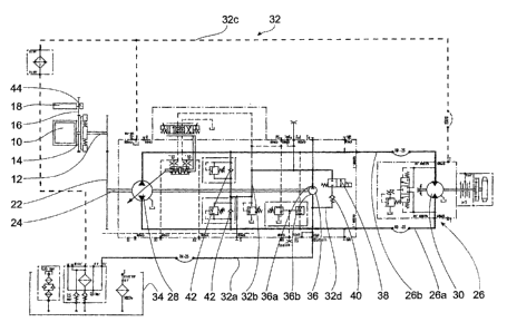
The drive system shown in figure 1 is associated with,
in a manner not illustrated in any more detail, a
tracked vehicle, in particular for shaping and
maintaining pistes and takes on the function of a
traction drive of a tracked vehicle. The principal
operation of the traction drive corresponds to the
embodiment shown in figure 2 such that reference is
made to the disclosure of the embodiment shown in
figure 2 in addition for the embodiment shown in figure
1. The figure merely shows a single drive side for one
of the two track drives. The part of the drive system
for the opposite track drive has a correspondingly
symmetrical design. The drive system has a drive
machine 10 in the form of an internal combustion
engine. A gearwheel I4 is provided on the output shaft
12 of said drive machine 10 and engages with a starter
pinion 16 of a starter motor 18 during starting of the
drive machine 10. The output shaft 12 of the drive
machine 10 is also operatively connected to a pump
shaft 24 via a distributor gear mechanism 22. In the
present embodiment, only one pump shaft 24 is shown.
For the opposite drive part of the other track drive,
the distributor gear mechanism on the output shaft 12
is designed such that it is connected in a
correspondingly symmetrical manner to an opposite pump
shaft and to an analogous part of the drive system.
The drive system also has a closed hydraulic circuit
26, which comprises two line sections 26a, 26b, which
are each connected to a variable-displacement pump 28
and a hydraulic motor 30. Depending on the desired
direction of rotation, in each case one line section
26a, 26b represents the high-pressure line, and the
other line section 26b, 26a represents the low-pressure
line. The closed circuit 26 is fed with hydraulic fluid
via an open circuit 32. The open circuit 32 has a first
line section 32a, which leads from a hydraulic fluid
tank 34 to a fixed-displacement pump 36 acting as a
(00022980.DOC}
CA 02528437 2005-11-30
- 16 -
feed pump for the closed circuit 26, a second line
section 32b, which leads from the fixed-displacement
pump 36 to the closed circuit 26, and a third line
section 32c, which acts as a leakage line and passes
the hydraulic fluid, which emerges from the closed
circuit 26 in the event of an excess pressure, back to
the hydraulic fluid tank 34.
In the region of the fixed-displacement pump 36, a
bypass path 32d is provided which connects an output-
side pump connection 36a of the fixed-displacement pump
36 to an input-side pump connection 36b of the fixed-
displacement pump 36. An electrically switchable
solenoid valve 38 and a spring-loaded nonreturn valve
40 are provided in the bypass path, said nonreturn
valve 40 only opening in the event of an excess
pressure present in the second line section 36b. The
electrically switchable solenoid valve 38 is designed
such that it is open when a voltage is applied.
Both the variable-displacement pump 28 and the fixed-
displacement pump 36 are supplied with mechanical power
via the pump shaft 24.
In the closed circuit 26, a pressure of 30 bar to 450
bar is set during operation in the respective high-
pressure line, and a pressure of 20 bar to 35 bar is
set in the low-pressure line. In the operating state,
the solenoid valve 38 is closed, and the bypass line
32d is consequently deactivated. A feed pressure of 20
to 35 bar likewise prevails in the supply line 32b
downstream of the fixed-displacement pump 36, and this
feed pressure is sufficient for supplying the hydraulic
fluid to the closed circuit 26 counter to nonreturn
valves 42. A pressure of approximately 1 bar prevails
in the section 32a between the hydraulic fluid tank 34
and the fixed-displacement pump 36. The fixed-
displacement pump 36 consequently needs to apply a
(00022980.DOC}
CA 02528437 2005-11-30
- 17 -
mechanical power during operation which is sufficient
to increase the pressure of the hydraulic fluid from 1
bar to approximately 20 to 35 bar.
The power required is so high that there is the risk of
the drive machine 10 stalling owing to the high power
requirement of the fixed-displacement pump 36 when said
drive machine 10 is started. In order to prevent this,
the solenoid valve 38 is opened during a starting
operation such that the bypass line 32d is activated.
As a result, the pressure in the line section 32c of
the open circuit 32 falls since the hydraulic fluid,
which is at a high pressure there, can flow away into
the hydraulic fluid tank 34 via the bypass line 32d and
the line section 32a. The spring-loaded nonreturn valve
40 prevents the excess pressure in the line section 32b
compared to the line section 32a being completely
dissipated. The spring-loaded nonreturn valve 40
ensures that a minimum pressure of 4 to 5 bar is
maintained in the line section 32b.
During the starting phase with the solenoid valve 38
open, a pressure of approximately 4 to 5 bar prevails
at the pump output and a pressure of only 1 bar
prevails at the pump input owing to the open solenoid
valve 38. The mechanical power required for operating
the fixed-displacement pump 36 is consequently
considerably reduced compared with that in the
operating state. The power consumption reduced in this
manner does not represent a problem for the drive
machine 10 when the drive machine 10 is started.
If the drive machine 10 has reached a speed which is
above the speed of the starter motor 18, the mechanical
operative connection between the starter pinion 16 and
the gearwheel 14 is disconnected. This is recognized by
a detector 44 provided for this purpose. In response to
the mechanical disconnection of the starter motor 18
(00022980.DOC}
CA 02528437 2005-11-30
- 18 -
and the output shaft 12 of the drive machine 10, the
solenoid valve 38 is closed via a control device (not
illustrated), with the result that the bypass line 32d
is interrupted. As a result, the pressure in the
section 32c of the open circuit 32 is increased again
by the fixed-displacement pump 36, whose power
requirement is again increased as a result until the
operating feed pressure of 20 to 35 bar is again
produced in the section 32c of the open circuit 32. In
the course of the rise in this pressure, the power
consumption of the fixed-displacement pump 36 also
increases until an operating power consumption is
reached, and the fixed-displacement pump 36 can assume
its function as a feed pump for the closed circuit 26.
The bypass line 32c to the solenoid valve 38 and the
nonreturn valve 40 thus makes it possible for the power
consumption of the fixed-displacement pump 36 to be
reduced during a starting phase to such an extent that
reliable run-up of the drive machine 10 is not impeded.
At the same time, the solenoid valve may also be
provided for the purpose of reducing the power
consumption of the feed pump of the track drive
opposite, in a manner which is not illustrated. In this
case, the bypass line is designed such that it detects
the two feed pumps and thus switching of the solenoid
valve at the same time brings about a corresponding
reduction in the power consumption of the two feed
pumps.
As an alternative, each feed pump has an associated,
dedicated bypass line, and in each case one solenoid
valve is provided in each bypass line. The two solenoid
valves are switched in particular at the same time in
analogy to the embodiments described.
(00022980.DOCJ
CA 02528437 2005-11-30
- 19 -
Figure 2 shows a second embodiment of a drive system
according to the invention. This system likewise serves
the purpose of driving a tracked vehicle 50. The left-
hand track 52 of the tracked vehicle 50 is driven via
an input gearwheel 54, which is in turn driven by a
hydraulic motor 56. The hydraulic motor 56 is part of a
closed hydraulic circuit 58. The hydraulic components
illustrated in figure 2 are all associated with the
left-hand track 52 of the tracked vehicle 52.
Corresponding components are provided for the right-
hand track (not illustrated in the drawing), but these
corresponding components are not shown. However, the
following description applies to the same extent to the
respective hydraulic components of the two tracks.
I5
The closed circuit 58 has two line sections 58a, 58b
which are connected with in each case one end to a
variable-displacement pump 60 and with the respective
other end to the hydraulic motor 56. Depending on the
conveying direction of the variable-displacement pump
60 and thus depending on the direction of rotation of
the hydraulic motor 56, one of the two line sections
58a, 58b represents the high-pressure line, and the
respective other represents the low-pressure line of
the closed circuit 58.
An open circuit 62 (only partially illustrated in the
drawing) is used for maintaining the operating pressure
in the closed circuit 58. In this open circuit 62,
hydraulic fluid is pumped into the closed circuit 58
from a hydraulic fluid tank 64 by a fixed-displacement
pump 66, nonreturn valves 68 preventing hydraulic fluid
from emerging from the closed circuit 58 into the open
circuit 62 counter to the pumping direction of the
fixed-displacement pump 66. A bypass line 62a is
provided in the open circuit 62 and connects a pump
output 66a of the fixed-displacement pump 66 to a pump
input 66b of the fixed-displacement pump 66. An
(00022980.DOC}
CA 02528437 2005-11-30
- 20 -
electrically switchable solenoid valve 70 and a spring
loaded nonreturn valve 72 are provided one behind the
other in the bypass line, said nonreturn valve 72
opening if there is a sufficient excess pressure on the
pump output side compared with the pump input side.
The variable-displacement pump 60 and the fixed
displacement pump 66 are supplied with mechanical power
via an output shaft 82 of an internal combustion engine
80. This mechanical coupling cannot be detached.
A generator 90 is likewise coupled to the output shaft
68 of the drive machine 70 via a belt drive 84 such
that it cannot be detached mechanically. This generator
90 is a three-phase machine having a field winding and
a stator winding. The field winding of the generator 90
can be interrupted by means of a relay (not
illustrated).
Furthermore, an electronic control device 100 is
provided which is connected to a starting switch 102
arranged in the driver's compartment. The control
device 100 is connected to a starter motor of the drive
machine 80 via a signal line 104a. In addition, the
control device 100 is connected to a frequency sensor
86, which measures the rotation frequency of the output
shaft 82 and passes this on to the control device 100
via a signal line 104b.
Furthermore, the control device 100 is connected to the
relay for the purpose of disconnecting the field
winding of the generator 90 and to the solenoid valve
70 via in each case one signal line 104c, 104d. As a
result, the relay of the generator 90 can be opened, on
the one hand, by means of a signal voltage from the
control device 100, with the result that the field
winding is not supplied with current, and, on the other
hand, the solenoid valve 70 can be opened such that the
~00022980,DOC}
CA 02528437 2005-11-30
- 21 -
bypass line 62a is opened between the pump output 66a
and the pump input 66b.
In order to start the drive machine 80, the starting
switch 102 is actuated by the driver of the vehicle. As
a result, the control device 80 receives a starting
pulse. In response to this starting pulse, a voltage is
applied to the signal lines 104c, 104d by the control
device 80. This has the result that, on the one hand,
the field winding in the generator 74 is interrupted by
means of the relay and, on the other hand, the valve 70
is opened. Subsequently, a voltage is applied to the
signal line 104a by the control device 100, as a result
of which starting of the drive machine 80 is brought
about by means of a starter motor (not illustrated).
Owing to the interruption of the field winding, a
countertorque, which acts counter to the drive torque
of the drive machine 80, is limited by the generator 90
to frictional losses and the moment of inertia, and is
therefore low. Owing to the opening of the valve 70,
the hydraulic fluid pressure on the pump output side is
reduced to a value, predetermined by the nonreturn
valve 84, of approximately 4 to 5 bar. The variable-
displacement pump 66 correspondingly merely needs to
pump against a pressure difference of approximately 3
to 4 bar. As a result, the countertorque, which acts
counter to the drive torque from the fixed-displacement
pump 66 on the output shaft 82 of the drive machine 80,
is also low.
Once the speed of the output shaft 82 has exceeded a
predetermined limit value, the control signal to the
control lines 104a, 104c is ended by the control device
100. As a result, firstly the starter motor of the
drive machine 80 is deactivated and secondly the field
winding of the generator 90 is closed again such that
the generator 90 begins to generate current.
{00022980.DOC)
CA 02528437 2005-11-30
- 22 -
Once a time interval, which has been fixedly
predetermined in the control device 100, has expired
once the control signal on the control lines 104a, 104c
has been ended, the control signal on the control line
104d is also ended, as a result of which the solenoid
valve 70 is closed such that the bypass line 62a is
interrupted and the pressure on the output side of the
fixed-displacement pump 66 begins to increase compared
with the minimum pressure predetermined by the
nonreturn valve 72. If the pressure on the pump output
side again corresponds approximately to the operating
pressure in the closed circuit 58, the operating state
of the tracked vehicle 50 has been reached.
The embodiment shown in figure 3 shows a block diagram
of a drive system for a tracked vehicle as shown in
figure 1, in which the drive parts of the two track
drive sides are illustrated. This drawing supplements
the already explained disclosure relating to the
embodiment shown in figure 1. Both feed pumps 36 are
integrated in a common bypass circuit 105, as shown in
figure 3, and an individual solenoid valve 38 is
associated with this bypass circuit 105. As a result,
the two feed pumps 36 can be short-circuited
simultaneously in a starting phase of the drive
machine, corresponding to the functional variants
described in detail above. Furthermore, two further
feed pumps 106, 107 are operatively connected to the
output shaft of the drive machine. These feed pumps
serve the purpose of supplying pressure to further
hydraulically operated systems of the tracked vehicle
such as a winch drive, a hydraulic fan drive for the
drive machine and the working hydraulics of the rear
carrier and the front-side attachment. In further
exemplary embodiments (not illustrated) of the
invention, these feed pumps 106, 107 are likewise
integrated in the common bypass circuit 105 or have a
dedicated bypass line.
(00022980.DOC}