Note: Descriptions are shown in the official language in which they were submitted.
CA 02528447 2005-12-06
WO 2005/097694 PCT/FI2005/050088
Method of heating glass panels for tempering and apparatus applying the method
The present invention relates to a method of heating glass panels for
tempering,
said method comprising heating horizontal glass panels by upper and lower
convection blast and by upper and lower radiation heating, reading information
that
represents a load of the glass panels and that is used for the control and/or
regulation of heating, controlling and/or regulating the upper radiation
heating in
the way of a matrix by a profiling both in a conveying direction and in a
direction
lateral thereto.
I n addition, the present invention relates to an apparatus for heating glass
panels
for tempering, said apparatus comprising horizontal conveyor rolls, upper and
lower
convection blast elements and upper and lower radiation heating elements, a
detector capable of reading information that represents a load of the glass
panels,
control devices for controlling and/or regulating the convection blast
elements and
radiation heating elements by means of the load-representing information, and
said
upper and lower radiation heating elements being divided in a conveying
direction
and in a direction lateral thereto into segments which have their heating
effects
adapted to be independently controlled and/or regulated.
This type of method and apparatus are known from the Applicant's patent
application FI 20020486, wherein the top and bottom sides of a glass panel are
heated with convection fans. The latter constitute convection heating zones
side by
side in the lateral direction of a tempering furnace, which zones are only
able to
provide a profiling that is transverse to the conveying direction. A similar
type of
apparatus is also disclosed in the Applicant's patent application FI 20011923.
This type of method and apparatus are capable of heating also the bottom side
of
glass in a profiled manner in a direction lateral to the conveying direction.
A
drawback is that production is relatively inflexible. I n other words, running
a mixed
production, which may involve a considerable variation in glass panel sizes,
will be
awkward and insufficient in terms of the adjustment of radiation heating and
convection blast.
CA 02528447 2005-12-06
WO 2005/097694 PCT/FI2005/050088
2
It is an object of the present invention to eliminate or substantially
mitigate the
above drawbacks. One of the objectives for a method and apparatus of the
present
invention is to provide flexible production by virtue of heat regulation
capabilities.
In order to accomplish the above objective, a method of the present invention
is
characterized in that at least the upper convection blast is controlled and/or
regulated in various sections of the lehr in the way of a matrix by a
profiling both in
a conveying direction and a direction lateral thereto, and that the relative
blast
effects of convection blast elements successive in the conveying direction are
regulated to provide a profiling in the conveying direction.
Furthermore, in order to accomplish the above objective, an apparatus applying
a
method of the present invention is characterized in that the upper convection
blast
elements are divided in the conveying direction and in a direction lateral
thereto
into segments or blocks which have their blast effects in various sections of
the lehr
adapted to be controlled and/or regulated in the way of a matrix, and that the
convection blast elements are provided with associated regulators for the
regulation
of relative blast effects of the successive convection blast elements.
Preferred embodiments for the present invention are set forth in the dependent
clai ms.
The invention will now be described in more detail with reference to the
accompanying drawings, in which:
Fg. 1 shows schematically an apparatus of the invention,
Fg. 2 shows schematically a control for upper convection blast elements, and
Fg. 3 shows schematically a control for lower convection blast elements.
Hence, in reference to fig. 1, there is shown an apparatus applying a method
of the
invention for heating glass panels. A glass panel is designated with reference
numeral 3. The apparatus comprises a conveyor, which is indicated by reference
CA 02528447 2005-12-06
WO 2005/097694 PCT/FI2005/050088
3
numeral 1. The conveyor comprises successive transfer rolls 2, having their
longitudinal axes set in a common horizontal plane. On top of the transfer
rolls 2
the glass panel 3 is carried in a conveying direction K into a lehr 4 for
heating the
glass panel 3 therein.
Prior to its transfer into the lehr 4, the glass panel 3 has its pertinent
information
read by a detector 9 provided for this purpose. The detector 9 includes at
least one
line camera 9c. A light source 9a is disposed below the glass panel 3 and
directed at
an acute angle relative to a normal of the glass panel 3. The light source 9a
is used
for transmitting light (indicated by a dashed line) to the glass panel's 3
surface. The
light reflected from the glass panel's 3 bottom is directed by means of a
deflection
mirror 9b to the camera 9c. The camera 9c transmits the image information to a
control system 21, 23 of the apparatus over a transmission path 20. I mage
information is preferably first transmitted to a logic 21 or a corresponding
processing device for interpreting and processing the image information
therein.
The logic interprets the light reflected to the camera as a glass panel. The
image
information is processed for appropriate control data or a parameter, which is
transferred further to a heating control and regulation device 23 over a
transmission
path 22. Other prior known devices used for identifying articles can of course
be
employed as well.
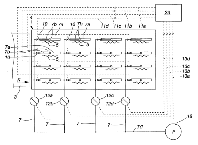
The lehr 4 includes upper radiation heating elements 5, a number of which are
disposed both side by side laterally to the conveying direction and
successively
along the conveying direction. According to the example shown in fig. 2, the
number of radiation heating elements 5 is four side by side and four in
succession.
The electric power supplied to each upper radiation heating element 5 is
controlled
and regulated independently by means of the control and regulation device 23,
the
adjusted electric powers being delivered therefrom over transmission paths 5b
to
the radiation heating elements 5.
Respectively, the lehr 4 is provided with lower radiation heating elements 6,
a
number of which are disposed both side by side laterally to the conveying
direction
(for example four) and successively along the conveying direction (for example
four). The electric power supplied to each lower radiation heating element 6
is
CA 02528447 2005-12-06
WO 2005/097694 PCT/FI2005/050088
4
controlled and regulated independently by means of the control and regulation
device 23, the adjusted electric powers being delivered therefrom over
transmission
paths 6b to the radiation heating elements 6.
The lehr 4 is further provided with upper convection blast pipes 7a for
delivering
convection air to the glass panel's 3 top surface. Fg. 2 illustrates
schematically one
inventive way of disposing the convection blast pipes 7a above the glass panel
3 in
the lehr 4, as well as for controlling and regulating the same. Fg. 2
visualises a
basic concept of the invention, according to which the upper convection blast
pipes
7a are divided both in a direction lateral to the advancing direction of a
glass panel
3 and along the advancing direction of a glass panel 3 into segments for
various
sections of the lehr. I n each section of the lehr, the glass panel 3 can have
the
same spot of its top surface subjected to a desired blast effect.
I n the present embodiment, each individual radiation heating element 5 is
provided
in its vicinity with discrete convection blast pipes 7a, such that the pipes
7a and the
radiation heating elements 5 have their lengthwise dimension essentially in
alignment with an advancing direction K of the glass panels 3. I n a direction
lateral
to the glass panel's 3 advancing direction, i.e. in a cross-lehr direction,
the pipes 7a
are disposed in four parallel zones. Furthermore, each parallel zone is
divided in the
glass panel's 3 advancing direction K, i.e. lengthwise of the lehr, into four
successive zones. Accordingly, the convection blast as a whole consists of
sixteen
components distributed in various sections of the lehr. This enables a matrix
type of
profiling for the glass panel 3, wherein a convection effect on the glass
panel 3 in
each section of the lehr 4 can be controlled and regulated independently. One
preferred working example regarding the control and regulation of upper
convection
blast will be described hereinafter.
The blast air is preferably delivered from a compressor's pressure vessel P to
a main
supply pipe 70. The main supply pipe 70 is branched for four supply pipes 7.
Each
supply pipe 7 is in turn provided for one lateral zone of the lehr 4 to be in
communication with each of the four convection blast pipes 7a of the relevant
zone.
This is implemented preferably by providing branch pipes 7b between the supply
pipe 7 and each convection blast pipe 7a. It should be appreciated that the
term
CA 02528447 2005-12-06
WO 2005/097694 PCT/FI2005/050088
pipes is used here in reference to air distribution ducts of various shapes
without
limiting to pipes of a circular cross-section as illustrated in the figures.
The air is
blasted by way of holes formed in the bottom part of a convection blast pipe
7a to
the top surface of a glass panel 3 presently underneath the discussed pipe 7a
(see
5 fig. 1 ). I nstead of holes, it is conceivable to employ for example jet
pipes as
described in the Applicant's patent application PCT/FI03/00673.
In association with all four supply pipes 7 are provided pressure regulators
12a,
12b, 12c and 12d. Each individual regulator is used for regulating a blast
pressure
of the supply pipe 7 in communication therewith and thereby concurrently a
blast
pressure or a total amount of air of the four convection blast pipes 7a
present in the
respective lateral zone. For example, the regulator 12a is used for regulating
the
first lateral zone in the lehr 4. The regulators 12a, 12b, 12c and 12d are
controlled
according to control data supplied over respective transmission paths 13a,
13b, 13c
and 13d. This enables an independent regulation regarding the blast effects of
each
lateral zone.
Moreover, each branch pipe 7b is fitted with valves 10. Controlling the valves
10 in
a subsequently described manner enables varying the amounts and/or blasting
times of convection air delivered through a convection blast pipe 7a in
communication with a respective branch pipe. The valves 10 are controlled
according to control data supplied from the control and regulation device 23
over
transmission paths 11 a, 11 b, 11 c and 11 d. I n this case, control of the
valves 10 is
organised by controlling simultaneously the valves 10 of those convection
blast
pipes 7a which are located in one lengthwise zone, i.e. essentially in
succession. For
example, as viewed from ahead of the regulation device 23 and the lehr 4,
between
the four valves 10 of a right-hand lengthwise zone is provided a transmission
path
11 a, by way of which the control data is delivered to each valve 10.
Preferably, the
valves 10 are on/off type valves but, as desired, can be supplemented with a
stepless or stepped regulation for the amount of convection air.
With this apparatus, convection blasts in successive pipes can all be switched
on at
the same time, but the relative blast effects thereof can be regulated by
means of
the regulators 12a, 12b, 12c and 12d set in connection with the supply pipes 7
for
CA 02528447 2005-12-06
WO 2005/097694 PCT/FI2005/050088
6
providing a lengthwise profiling in the convection blast. At the same time,
convection blasts in parallel pipes of a lateral zone can be switched on and
off at
various times for various durations for providing a lateral profiling in the
convection
blast.
As shown in fig. 1, in addition to the upper convection blast pipes 7a, the
apparatus
includes also lower convection blast pipes 8a.
Fg. 3 depicts a schematic view for applying a convection blast from below to
the
glass panel's 3 bottom surface. The blast air is preferably delivered from a
pressure
vessel P to a main supply pipe 80 which is branched for four supply pipes 8.
Each
supply pipe 8 is in turn provided for one lateral zone of the lehr 4 to be in
communication with each of the four convection blast pipes 8a of the relevant
zone.
This is implemented preferably by providing branch pipes 8b between the supply
pipe 8 and each convection blast pipe 8a. The air is blasted by way of holes
formed
in the top part of a convection blast pipe 8a to the bottom surface of a glass
panel
3 presently underneath the discussed pipe 8a (see fig. 1 ).
A pressure regulator 16a, 16b, 16c and 16d set in communication with each of
the
four supply pipes 8 is used for regulating a blast pressure in the supply pipe
8
presently in communication with the regulator. The regulators 16a, 16b, 16c
and
16d are controlled according to control data supplied from the control and
regulation device 23 over transmission paths 17a, 17b, 17c and 17d. At the
same
time, the control applies to a blast pressure or a total amount of air of the
four
convection blast pipes 8a located in the respective lateral zone, as described
in
reference to the top-side convection blast pipes. This enables an independent
regulation regarding the blast effects of each lateral zone.
Each branch pipe 8b is fitted with valves 14, which can be controlled for
varying the
amounts and/or blasting times of convection air delivered through a convection
blowpipe 8a in communication with a respective branch pipe. The valves 14 are
controlled according to control data supplied from the control and regulation
device
23 over transmission paths 15a, 15b, 15c and 15d, also in this case preferably
by
CA 02528447 2005-12-06
WO 2005/097694 PCT/FI2005/050088
7
controlling simultaneously the valves 14 of those convection blast pipes 8a
which
are located in one lengthwise zone, i.e. essentially in succession.
The present invention is not limited to the described embodiment, but can be
modified in many aspects. For example, the number of lengthwise and lateral
zones
may vary, control and regulation for various zones can be provided also in
other
ways than connected in series by way of the branch pipes 7b, 8b. Each
convection
blast pipe can be controlled and regulated independently as desired.