Note: Descriptions are shown in the official language in which they were submitted.
CA 02528629 2005-12-08
WO 2004/110922 PCT/US2004/017489
FIELD-ASSISTED GAS STORAGE MATERIALS AND
FUEL CELLS COMPRISING SAME
FIELD OF THE INVENTION
The present invention relates generally to field-assisted gas storage
materials. More
specifically, the present invention relates to field-assisted gas storage
materials,
wherein the gas storage density or solubility and mobility, as well as the
uptake and
discharge of gas, can all be controlled by application of a field. Even more
specifically, the present invention relates to field-assisted hydrogen storage
materials,
and fuel cells comprising the same, where the hydrogen density or solubility
and
mobility, as well as the uptake and discharge of hydrogen, can all be
controlled by
application of a field.
BACKGROUND OF THE INVENTION
Fuel cell technology is a rapidly growing industry with many potentially far-
reaching
benefits.. The current market for fuel cells is approximately $218 million, an
amount
that has been projected to rise to $2.4 billion by 2004, and to $7 billion by
2009. If
successfully implemented, fuel cell technology is expected to provide, among
other
benefits, improved national energy security due to reduced reliance on foreign
fossil
fuels and enhanced air quality due to markedly reduced emission of airborne
pollutants.
Fuel cells are capable of extremely efficient energy conversion, and can be
used for
both transportation and stationary applications. For transportation
applications, fuel
cell vehicles present a promising alternative to conventional internal
combustion
engine vehicles. Fuel cell vehicles may be fueled with hydrogen, and emit only
water
and energy, whereas conventional internal combustion engine vehicles burn
fossil
fuels such as gasoline or diesel, and emit harmful particuhates and greenhouse
gases to
the atmosphere.
1
CA 02528629 2005-12-08
WO 2004/110922 PCT/US2004/017489
There are many additional advantages to fuel cell vehicles. Fuel cell vehicles
may be
up to three times or more energy efficient than conventional vehicles. Fuel
cell
vehicles may convert between 40-45% or more of the energy in the provided fuel
into
power, where conventional internal combustion engine vehicles convert only
about
16% of the energy in the provided fuel into power. Additionally, because fuel
cell
vehicles operate with electric motors that have very few moving parts (i.e.,
only those
pumps and blowers that are needed to provide fuel and coolant), vehicle
vibrations
and noise will be vastly reduced in fuel cell vehicles, and routine
maintenance (i.e., oil
changes, spark plug replacement, etc.) will be eliminated.
Fuel cells operate very much like batteries that can be recharged while power
is being
drawn. However, while batteries are recharged using electricity, fuels cells
are
recharged using hydrogen. Typically, hydrogen fuel cells operate by converting
the
chemical energy in hydrogen and oxygen into water, producing electricity and
heat,
which is then fed into an electric motor that powers the wheels of a fuel cell
vehicle.
Hydrogen is considered in the art to be an ideal fuel for fuel cell vehicles.
Hydrogen
is the most plentiful element in the universe, is the third most plentiful
element on
Earth, can be derived from multiple renewable energies, and, when consumed as
fuel
in a fuel cell, produces only water without the production of greenhouse gases
such as
carbon dioxide. Conventional means of storing hydrogen for end use delivery
include: (1) liquid or gaseous hydrogen, (2) hydrocarbon fuels (i.e., fossil
fuels), and
(3) solid materials (i.e., metal hydrides).
Using liquid or gaseous hydrogen as the energy source in a fuel cell is not
ideal.
Hydrogen is highly flammable and requires a low hydrogen-to-air concentration
for
combustion. Furthermore, hydrogen is harder to transport and store than other
liquid
fuels. Additionally, there is currently only a very limited infrastructure
available for
distributing hydrogen to the public.
To avoid the disadvantages presented by the use of pure hydrogen as a fuel,
many fuel
cell designs focus on using hydrocarbon or alcohol fuels, such as methanol,
natural
gas and petroleum distillates. However, these designs present disadvantages of
their
2
CA 02528629 2005-12-08
WO 2004/110922 PCT/US2004/017489
own, such as, for example, the need for fuel reformers, which break down the
hydrocarbon fuel into hydrogen, carbon dioxide and water. The hydrogen
produced
by such reformers is not pure, which lowers the efficiency of the fuel cell.
Furthermore, adding a reformer to convert hydrocarbon fuel into hydrogen may
drop
the overall efficiency of the fuel cell to about 30 to 40 percent. Additional
disadvantages of using hydrocarbon fuels include: (1) onboard reformers add to
the
complexity, cost and maintenance of the fuel cell system; (2) if the reformer
allows
carbon dioxide to reach the fuel cell anode, the performance of the cell will
be
gradually decreased; and (3) reformers produce greenhouse gases and other air
pollutants.
Hydrogen storage materials, which chemically store the hydrogen fuel, are
considered
to be an advantageous source of hydrogen for fuel cells in a wide range of
potential
applications. However, getting sufficient hydrogen solubility, storage
density, and
mobility in such materials has proven to be difficult. Furthermore, the
ability to
control the rates of hydrogen uptake and release over a broad range of power
output
for applications such as fuel cells has not yet been achieved. Therefore,
improved
hydrogen storage materials are desired for a variety of applications,
including
selective hydrogen separation from other gases, catalysis, and fuel cells for
vehicles,
personal power generation, and stationary power generation.
Extensive research activity in the past 30 or so years has focused on storing
hydrogen
in the form of solid metal hydrides. Metal hydrides are typically generated
exothermically when metals and alloys are exposed to hydrogen. Most of the
hydrogen reacts with these metals and/or alloys and forms new compounds, while
a
smaller portion of the hydrogen decomposes into atomic hydrogen in the
exothermic
reaction and subsequently enters interstices in the metal lattice. The
hydrogen can be
recovered for use from therein by heating, by electrolytic oxidation of the
hydride, or
by a reaction with an oxide or water. One advantage of using a metal hydride
for
hydrogen storage is that the volume density for hydrogen storage in metal
hydrides is
relatively large in comparison to other storage media. However, recovering the
hydrogen from the hydride is difficult, as is regenerating the metal.
Moreover, the
metal adds significant weight to the fuel cell system.
3
CA 02528629 2005-12-08
WO 2004/110922 PCT/US2004/017489
Examples of well-known hydrogen storage materials include metal hydrides, such
as
FeTiH2 and LaNi5H6, which contain about 1.9 and about 1.5 percent by weight
hydrogen respectively, that release hydrogen upon heating. Even though FeTiH2
and
LaNi5H6 have acceptable recovery temperatures, the hydrogen content in terms
of
weight percent is too low for use in vehicular fuel cell applications. Other
metal
hydrides, such as MgH2 and TiH2, have higher hydrogen contents, about 7.6 and
about
4.0 percent by weight respectively, but must be heated to high temperatures
(i.e.,
above about 100°C) in order to recover the hydrogen. Other drawbacks to
the use of
metal hydrides as gas storage materials include disproportionation, poisoning,
accompanying losses of capacity, and the need for regeneration of some of the
storage
alloys.
Carbon nanotubes are another potential hydrogen storage material that has been
studied extensively. Carbon nanotubes are fullerene-related structures that
consist of
seamless graphite cylinders closed at either end with caps containing
pentagonal
rings. Carbon nanotube powders tend to pack inefficiently and have poor
volumetric
efficiency. Furthermore, carbon nanotubes are very expensive to produce, and
currently are not available in the quantities that are needed for commercial
hydrogen
storage applications.
Other well-known hydrogen storage materials include zeolites, which are highly
porous crystalline aluminosilicates. However, the hydrogen storage capacity of
zeolites, in terms of mass of hydrogen per unit weight of zeolite, is
inadequate for
vehicular fuel cell applications. Additionally, zeolites must be heated to
trigger the
release of hydrogen therefrom, and the response time in large cross sections
of
zeolites is limited by thermal diffusion.
The future hydrogen economy requires efficient ways to store and transport
hydrogen
for automobile and distributed power fuel cell applications, and numerous
other
applications. Several methods have been proposed for hydrogen storage,
including
those discussed above, but currently, none of the materials or methods has
demonstrated the desired hydrogen solubility and storage density, hydrogen
mobility,
and/or hydrogen uptake/release capability needed for commercial applications.
4
CA 02528629 2005-12-08
WO 2004/110922 PCT/US2004/017489
Therefore, it would be desirable to have hydrogen storage materials that do
not have
all the drawbacks of the current hydrogen storage materials.
Additionally, while hydrogen storage materials have been described above,
various
other gases may also be stored in gas storage materials, and such gas storage
materials
can be utilized for a variety of purposes, such as for gas separation,
emissions
sequestration, and drying of gas flows. Improved gas storage materials,
capable of
storing gas other than hydrogen, are also desired.
Therefore, it would be desirable to have gas storage materials that are light,
compact,
relatively inexpensive, safe, and easy to use. It would be further desirable
to have gas
storage materials that provide higher gas solubility (i.e., higher gas storage
densities)
and higher gas mobility than currently possible. It would also be desirable to
have
such materials comprise a mechanism that allows the charging/uptake and
releasing of
gas to be well controlled.
SUMMARY OF THE INVENTION
These and other needs are addressed by embodiments of the present invention.
Gas
storage materials used in the embodiments described herein include a wide
variety of
material compositions and types, and are light, compact, relatively
inexpensive, safe,
easy to use. Moreover, embodiments of the present invention may provide for
more
efficient and controlled storage and retrieval of gas from gas storage
materials, at
temperatures below those required by conventional gas storage materials.
Embodiments of this invention comprise gas storage materials having high gas
storage density and high gas mobility. These gas storage materials may
comprise a
material comprising gas storage space and enough ionic character to sustain an
electric dipole during application of an applied field, wherein the
application of the
applied field does not cause the material to become conductive; and a gas
stored
within the gas storage space in the material, wherein the gas is capable of
diffusing
through the material. The applied field herein is comprised of an electric
field,
possibly combined with a stress field or a strain field.
CA 02528629 2005-12-08
WO 2004/110922 PCT/US2004/017489
Other embodiments of this invention comprise high capacity gas storage
materials.
These gas storage materials may comprise a material comprising a crystal
structure
and enough ionic character to sustain an electric dipole during application of
an
applied field, wherein the application of the applied field does not cause the
material
to become conductive; and gas stored within the material, wherein the crystal
structure comprises a specifically engineered crystal structure that comprises
dipoles
that allow the engineered crystal structure to hold a predetermined amount of
stored
gas; and wherein the stored gas bonds with the engineered crystal structure,
reducing
the free energy of the material, thereby increasing the effective gas
solubility of the
material. These gas storage materials may further comprise a mechanism for
controlling uptake of gas thereto and release of gas therefrom. The mechanism
may
comprise an applied field (i.e., an electric field, a stress field, a strain
field, and
combinations of these).
The gas storage materials utilizing an applied electric field may comprise a
dielectric
material, a piezoelectric material, a ferroelectric material, a ceramic
material, a non-
metal material, a polymer material, a semiconductor material, and/or any other
suitable material.
Yet other embodiments of this invention comprise gas storage materials having
a high
gas storage density and high gas mobility. These gas storage materials may
comprise
a material comprising gas storage space and enough magnetic character to allow
magnetic dipoles therein to be aligned during application of an applied field;
and a gas
stored within the gas storage space in the material, wherein the gas is
capable of
diffusing through the material. The applied field in these embodiments may
comprise
a magnetic field alone or combined with a stress field, and/or a strain field.
These gas
storage materials may comprise a magnetic material comprising ferromagnetic
elements, wherein the magnetic material is incorporated into a solid-state
material, a
metal, a ceramic, a polymer, and/or a composite of magnetic and non-magnetic
materials.
Still other embodiments of this invention comprise gas storage materials
having a
high gas storage density and high gas mobility. These gas storage materials
may
6
CA 02528629 2005-12-08
WO 2004/110922 PCT/US2004/017489
comprise: a material comprising: (a) gas storage space; (b) enough ionic
character to
sustain an electric dipole during application of an applied electric field;
and (c)
enough magnetic character to allow magnetic dipoles therein to be enhanced
during
application of an applied magnetic field; and a gas stored within the gas
storage space
in the material, wherein the gas is capable of diffusing through the material
and
wherein application of the applied electric field and the applied magnetic
field allows
at least one of the following to be controlled: (a) gas solubility of the gas
storage
material; (b) gas uptake to the gas storage material; (c) gas discharge from
the gas
storage material; and (d) gas mobility within the gas storage material.
In the gas storage materials of this invention, application of the applied
field allows
one or more of the following things to be controlled: (a) gas solubility of
the gas
storage material; (b) gas uptake to the gas storage material; (c) gas
discharge from the
gas storage material; and (d) gas mobility within the gas storage material.
The gases stored within any of these gas storage materials may comprise
hydrogen, a
gas with a permanent dipole (i.e., carbon dioxide), a polarizable gas capable
of
molecular or atomic transport through the storage material (i.e., nitrogen in
zeolites),
and/or any other suitable gas.
In embodiments of this invention, the average occupancy rate of gas molecules
per
available gas storage space is greater than about 25%.
The diffusion paths in the gas storage materials of this invention may
comprise grain
boundaries, porosity (i.e., natural or engineered porosity), defects (i.e., a
dislocation in
the crystal lattice structure of the material, a planar defect in the crystal
lattice
structure of the material, a surface impurity, a step in the crystal lattice
structure of the
material, etc.), intrinsic structure of the gas storage material, and/or bulk
of the gas
storage material.
In embodiments, the gas storage space or gas storage density may be at least
partially
created in many ways, such as for example by: (a) chemically altering the
crystal
lattice structure of the material by substituting aliovalent canons and
anions; (b)
creating defects in the crystal lattice structure of the material so
interstitials exist in
7
CA 02528629 2005-12-08
WO 2004/110922 PCT/US2004/017489
sublattices of the material; (c) creating defects in the crystal lattice
structure of the
material so vacancies exist in sublattices of the material; (d) selectively
altering the
crystal lattice structure of the material so as to provide gas diffusion paths
that allow
gas mobility within the material; and/or (e) introducing dipoles into the
material via
the applied field, or the like.
Other embodiments of this invention comprise fuel cells comprising the gas
storage
materials discussed above.
Further features, aspects and advantages of the present invention will be more
readily
apparent to those skilled in the art during the course of the following
description,
wherein references are made to the accompanying figures which illustrate some
preferred forms of the present invention, and wherein like characters of
reference
designate like parts throughout the drawings.
DESCRIPTION OF THE DRAWINGS
The systems and methods of the present invention are described herein below
with
reference to various figures, in which:
Figure 1 is a diagram showing the dissociation of molecular hydrogen and its
storage
in a hydrogen storage material as atomic hydrogen, as utilized in embodiments
of this
invention;
Figure 2 is a diagram showing the dissociation of molecular hydrogen and its
storage
in a hydrogen storage material as protonic hydrogen, as utilized in
embodiments of
this invention; and
Figure 3 is a diagram showing the storage of molecular hydrogen in a hydrogen
storage material, as utilized in embodiments of this invention.
DETAILED DESCRIPTION OF THE INVENTION
For the purposes of promoting an understanding of the invention, reference
will now
be made to some embodiments of the present invention as illustrated in FIGURES
1-3
and specific language used to describe the same. The terminology used herein
is for
CA 02528629 2005-12-08
WO 2004/110922 PCT/US2004/017489
the purpose of description, not limitation. Specific structural and functional
details
disclosed herein are not to be interpreted as limiting, but merely as a basis
for the
claims as a representative basis for teaching one skilled in the art to
variously employ
the present invention. Any modifications or variations in the depicted support
structures and methods of making same, and such further applications of the
principles of the invention as illustrated herein, as would normally occur to
one
skilled in the art, are considered to be within the spirit of this invention.
In accordance with one embodiment of the invention, a gas storage system 8
comprising at least one gas storage material 14 and at least one field 10
applied upon
the gas storage material 14 to control the gas solubility of the gas storage
material 14,
is shown in FIGS 1-3. Typically, although not necessarily, the gas stored
within gas
storage system 8 comprises hydrogen. Hydrogen comprises ionic hydrogen,
molecular hydrogen, atomic hydrogen, deuterium, tritium, any combinations
thereof,
or the like. Other gases that may be stored in gas storage system 8 comprise
Carbon
Monoxide, Oxygen, Carbon Dioxide, Nitrogen, Methane, and oxides of nitrogen
and
sulphur and combinations thereof or any gas that is polar or capable of
polarization.
In one embodiment, the gas storage material 14 comprises a dielectric. If the
gas
storage material 14 is a dielectric material, the at least one field 10
typically
comprises an electric field (as depicted in FIGS 1-3), a stress field, a
strain field, or.
combinations thereof. The gas storage system 8 typically comprises additional
features such as temperature control mean and pressure control means. In some
embodiments, the dielectric material comprises at least one of a
piezoelectric, a
ferroelectric, a ceramic, a non-metal, an organic material, or a semiconductor
material. In the case of a piezoelectric storage material, one embodiment
comprises
barium titanate. In the case of ceramics, one embodiment comprises V205. In
the case
of organic materials, one embodiment comprises polyvinylidene fluoride, (PVDF)
or
a microporous metal-organic framework.
In another embodiment, the gas storage material 14 comprises a magnetic
material,
for example a ferromagnetic, a paramagnetic, a diamagnetic, or a ferrimagnetic
material. If the gas storage material 14 is a magnetic material, then at least
one field
9
CA 02528629 2005-12-08
WO 2004/110922 PCT/US2004/017489
typically comprises a magnetic field, possibly in combination with other
fields, for
example, stress, strain, or electric fields and combinations thereof. In one
embodiment, the ferromagnetic material comprises at least one of iron, cobalt,
manganese, nickel and combinations, alloys and compounds thereof.
This invention typically relates to gas storage materials comprising a high
density of
useable hydrogen or other gas storage sites, both per unit mass and per unit
volume of
storage material. While many of these gas storage sites may comprise low
energy
lattice or defect sites that exist naturally, or that are created via chemical
changes to
the crystallographic structure, the gas storage sites are created via field-
induced
changes to the crystallographic structure of the material. Such changes yield
gas
storage materials having increased gas mobility and solubility, as well as a
gating
mechanism for controlling the charging of gas to and the releasing of gas from
the
crystallographic structure. Additionally, these materials are durable,
thermally and
chemically stable, and can be made for relatively low cost. As used herein,
the term
solubility means "the capacity to store a quantity of gas in the bulk of a
material, on
the surface of a material, or combinations thereof."
The solubility of gas in gas storage materials may be increased by the
creation of
bonding sites that result from dipoles being created in the crystallographic
structures
of the gas storage materials. Dipoles may be created or enhanced in such
materials.by
altering the stoichiometry of the base compound. Such alterations may be
achieved in
numerous ways, such as, for example, by chemically substituting aliovalent
cations
and anions. In accordance with the instant invention, dipoles may also be
created or
enhanced in materials via fields (i.e., via stress field, strain fields,
and/or via electric
and/or magnetic fields). The solubility of a gas in gas storage materials may
be
enhanced by creating crystallographic defects in the structure of the
materials so that
interstitials and vacancies exist in the sublattices of the materials.
Selective alteration
of the crystal structure of a material may also provide easier diffusion paths
for the
gas. The changes to the structure of some base compounds give rise to local
electronic or magnetic dipoles that provide attachment sites for gas. The
field-
induced and field-enhanced dipoles polarize the gas atom, which gas atom
orients
itself with respect to the dipole so as to reduce the total free energy of the
system.
CA 02528629 2005-12-08
WO 2004/110922 PCT/US2004/017489
These dipoles attract and hold gas atoms while a field is being applied during
charging, and then removal of the field lowers the effective solubility of the
gas in the
material by eliminating the dipole, thereby causing the gas to be released.
Reversal of
the field can be employed to drive off residual gases that may be retained by
permanent dipoles or that require additional activation for release.
Controlling the
application of the field serves as a switching or gating mechanism that allows
the
uptake of gas during charging, and the release of gas during a demand cycle,
to be
controlled.
While metals and metal hydrides have long been used as hydrogen storage
materials,
the materials of this invention may prove to be more preferable hydrogen or
other gas
storage materials. The materials of this invention provide enhanced gas
mobility and
solubility when used as gas storage materials. For example, most ceramics
comprise
mainly ionic bonds having centers of positive and negative charge within their
structures, but some ceramics (i.e., A1203, SiC) may also have a substantial
amount of
covalent bonds that are directional bonds. Metals, on the other hand, comprise
metallic bonds (i.e., basically a sea of electrons), while metal hydrides
comprise
mainly covalent bonds, with some metallic and ionic bonds. Materials that have
predominantly ionic or covalent bonds (i.e., ceramics) react to electric
fields, and to
other ions that are put into the materials, by rearranging their structure,
thereby
changing the shape, physical structure or electronic structure of the
material, without
causing the material to become conductive. Materials that have unpaired
electrons,
particularly certain d- or f series elements (i.e., Fe, Co, Nd, Sm), will
align internal
magnetic dipoles in response to a magnetic field. This response will be
observed in
materials having metallic, ionic or covalent bonding.
In other words, materials having predominantly ionic character (i.e.,
ceramics) show
or have the potential for Van der Waals bonding (i.e., dipole-dipole
interactions).
Applying electric fields external to such predominantly ionic character
materials, this
invention enhances the electric dipoles in the material, and encourages Van
der
Waals-like bonding with a gas, such as hydrogen. The gas responds by
polarizing
(i.e., shifting the electron orbit), to counter the field-induced dipole,
thereby lowering
the free energy of the system. In contrast, materials having metal-like
conductivity
11
CA 02528629 2005-12-08
WO 2004/110922 PCT/US2004/017489
dissipate the applied electric field by the motion of their unbound electrons,
thereby
precluding electric dipole formation, and making such materials unsuitable for
use
with an applied electric field.
In other embodiments of this invention, application of a magnetic field,
instead of an
electric field, may be more desirable to enhance the gas solubility or
mobility. For
example, when a magnetic field is applied to materials having a significant
amount of
magnetic character, the permanent magnetic dipoles therein are aligned,
thereby
increasing the 'solubility and mobility of the gas that may be stored therein.
Hydrogen, having a single, unpaired electron and a single proton, is ideally
suited to
respond to magnetic fields.
Using fields, for example electric, magnetic, stress and strain fields, to
control the
uptake and release of gas in the gas storage materials of this invention
allows for
much quicker response times to be realized than currently possible with
typical
pressure-activated or temperature-activated gas storage materials. The typical
pressure-activated or temperature-activated gas storage materials experience a
lag in
the response time from when the pressure or temperature is applied.
Additionally, the
high temperature (>100°C) required for most metal hydrides to discharge
the gases
stored therein is a problem. In contrast, the gas storage materials of this
invention
have an essentially instantaneous response time to a field at any temperature,
making
them ideal for a wide variety of applications, such as for example, vehicular
fuel cell
applications. The fields herein are potentially used to: (1) increase the
solubility of
the gas in the gas storage materials, (2) take advantage of the quick response
time of
the material instead of relying on the thermal diffusivity of the material,
(3) throttle
the release of gas in proportion to field strength, and (4) allow low
temperature
desorption of the gas.
Silicate materials, such as micas, zeolites, and vermiculites, are comprised
of open
channels and layered structures, which allow rapid access of hydrogen or other
gas to
their interiors along those easy diffusion paths. In materials such as
zeolite, the gas is
trapped at storage sites within cage-like crystallographic structures defined
by
polyhedra comprising Si , Al', Mg, Na, O- and F-, for example. Most gas
adsorption
12
CA 02528629 2005-12-08
WO 2004/110922 PCT/US2004/017489
in zeolites is strongly controlled by internal electric fields such as those
described
above. These internal electric fields and the structures that support them may
be
modified by chemically tailoring the crystallographic structure. Additionally,
crystal
chemical manipulation can alter the size of the gas diffusion paths, alter the
size of the
storage cages, or alter the electronic state of the storage cages, so the
material accepts
and holds more gas, even in the absence of an applied field, and allows it to
diffuse
therethrough more rapidly. Additionally, a field, such as an electric or
magnetic field,
may be applied to such structures to enhance the gas storage capacity and
release
capability thereof.
Ferroelectric materials, ferromagnetic materials, piezoelectric materials and
dielectric
materials in particular, axe ideal materials for modifying, either chemically
or via
application of a field, to enhance the gas storage capacity/solubility and gas
mobility
thereof, and are also ideal for using a field to control the uptake and
release of gas.
Piezoelectrics are one type of ceramic material wherein an applied field
(i.e., stress,
strain or electric field) can induce a large internal dipole. Stress or strain
on a
piezoelectric material results in a separation of the centers of positive and
negative
charges leading to a field-induced dipole. This field-induced dipole serves to
attract a
gas such as hydrogen, which polarizes and arranges itself to form a Van der
Waals-
like bond, thereby reducing the free energy of the system and counteracting
the field-
induced dipole. The net effect thereof is an increase of hydrogen solubility
in the
piezoelectric storage material. Removal, reversal, or decrease of the stress
or strain
changes the dipole strength and alters, in the desired manner, the hydrogen
solubility
of the piezoelectric storage material, thereby establishing a gating mechanism
for
controlling the uptake and release of hydrogen.
The reverse piezoelectric effect may also be used to create a field-induced
dipole. In
this case, the field may be an electric field, instead of a stress or strain
field, which
may be more conveniently applied to the piezoelectric material via electrodes
attached
to the piezoelectric material. Electric fields also produce displacements in
the
piezoelectric material, along with an attendant induced dipole. Hydrogen in
its atomic
or protonic form may have higher mobility in certain materials than molecular
hydrogen. Therefore, in order to take advantage of this phenomenon, known
catalytic
13
CA 02528629 2005-12-08
WO 2004/110922 PCT/US2004/017489
materials (i.e., Pd and Pt) for the separation of molecular hydrogen into
atomic
hydrogen may be employed as the electrodes during application of the electric
field.
When the electric field is applied, molecular hydrogen is dissociated into
atomic
hydrogen by the catalytic electrodes, dissolved therein, and transported
therethrough
to the storage material. Such catalysts may be used, even in the absence of an
applied
electric field, to transform molecular hydrogen into a more mobile form for
transport
through the material.
Most ceramics are not known for having high hydrogen diffusivity rates. As
moving
gas into and out of these gas storage materials as quickly as possible is
advantageous
to the operation of gas storage systems, it would be beneficial to improve the
gas
diffusivity rates, or to have some other way to get the gas into and out of
the gas
storage material without having to diffuse it over long distances through the
bulk of
the material. One way to get gas into and out of the gas storage material
quickly is to
take advantage of high gas diffusivity paths in the gas storage material. Such
paths
may exist in the material naturally, or they may be intentionally created. For
example, grain boundaries, defect structures and dislocations are naturally
occurring
high hydrogen diffusivity paths. Engineered porosity or other defects may also
be
intentionally created within a material so as to provide additional high gas
diffusivity
paths in a material. Utilizing materials that comprise both field-induced
dipoles for
increasing the gas solubility therein, and high mobility diffusion paths for
increasing
the gas mobility therein, would be ideal.
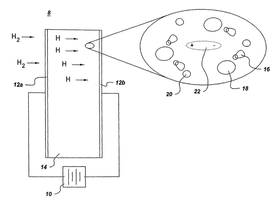
Referring now to Figure 1, there is shown a diagram showing the dissociation
of
molecular hydrogen and its storage in a hydrogen storage material as atomic
hydrogen, as utilized in one exemplary embodiment of this invention. In this
embodiment, an electric field 10 is applied to two electrodes 12a, 12b
surrounding the
gas storage material 14, which in this case is depicted as being a hydrogen
storage
material. Preferably, the electrodes comprise a material that actively breaks
down H2
(molecular hydrogen) into H (atomic hydrogen), such as for example, platinum
or
palladium. As shown in the enlarged section of this diagram, once the electric
field is
applied and the molecular hydrogen is broken down into atomic hydrogen, the
atomic
hydrogen 16 polarizes and aligns itself with the anions 18 and cations 20 in
the
14
CA 02528629 2005-12-08
WO 2004/110922 PCT/US2004/017489
storage material. The virtual dipole 22 that is created is the result of the
combined
effects of the applied field, the composition of the material, and the
structure thereof.
Therefore, it can be seen that such application of an electric field enhances
the
hydrogen solubility of this hydrogen storage material, thereby acting as a
gating
mechanism for controlling the uptake and release of hydrogen.
Referring now to Figure 2, there is shown a diagram showing the dissociation
of
molecular hydrogen and its storage in a hydrogen storage material as protonic
hydrogen, as utilized in one exemplary embodiment of this invention. In this
embodiment, an electric field 10 is applied to two electrodes 12a, 12b
surrounding the
gas storage material 14, which in this case is depicted as being a hydrogen
storage
material. Preferably, the electrodes comprise a material that actively breaks
down H2
(molecular hydrogen) into H+ (protonic hydrogen) with the assistance of an
applied
electric field, such as for example, Pd or Pt. As shown in the enlarged
section of this
diagram, once the electric field is applied and the molecular hydrogen is
broken down
into protonic hydrogen, the protonic hydrogen 17 diffuses into the material
along the
field gradient, and aligns itself with the anions 18 and cations 20 in the
storage
material. The virtual dipole 22 that is created is the result of the combined
effects of
the applied electric field, the composition of.the material, and the structure
thereof.
The electrons can be stored in an external capacitor until the release of
hydrogen is
required. Therefore, it can be seen that such application of an electric field
enhances
the hydrogen solubility of this hydrogen storage material, thereby acting as a
gating
mechanism for controlling the uptake and release of hydrogen.
Referring now to Figure 3, there is shown a diagram showing the storage of
molecular
hydrogen in a hydrogen storage material, as utilized in one exemplary
embodiment of
this invention. In this embodiment, an electric field 10 is applied to two
electrodes
12a, 12b surrounding the gas storage material 14, which in this case is
depicted as
being a hydrogen storage material. In this embodiment, the structure of the
hydrogen
storage material 14 must be open enough to accept H2 as is. Zeolites may work
well
for such storage. As shown in the enlarged section of this diagram, once the
electric
field is applied, the molecular hydrogen diffuses through the open zeolite
channels
formed by assemblages of cages 16 until it encounters a dipole storage site.
The
CA 02528629 2005-12-08
WO 2004/110922 PCT/US2004/017489
dipole storage site can be native to the base zeolite material, it can be
created or
enhanced by chemical alterations, or it can be created or enhanced by an
applied field.
The molecular hydrogen then polarizes in response to the dipole site and
aligns itself
with the anions and cations in the storage material. Many locations within
various
specific cages are known to serve as sites for hydrogen storage. Therefore, it
can be
seen that such application of an electric field enhances the hydrogen
solubility of this
hydrogen storage material, thereby acting as a gating mechanism for
controlling the
uptake and release of hydrogen.
While several different manners of storing hydrogen in a hydrogen storage
material
have just been described, this invention contemplates the storage of any
suitable gas
in any suitable material. Therefore, all such embodiments are intended to be
covered
within the spirit and scope of this invention.
As described above, the gas storage materials of this invention allow high
performance gas storage materials to be realized for a variety of
applications, such as
for fuels cells and vehicles comprising the same. Advantageously, the gas
storage
materials of this invention show tremendous promise for commercial, industrial
and
consumer uses. These materials may be used for gas phase storage, and are
particularly well suited for vehicular fuel cell applications. Many other
advantages
will also be apparent to those skilled in the relevant art.
Various embodiments of this invention have been described in fulfillment of
the
various needs that the invention meets. It should be recognized that these
embodiments are merely illustrative of the principles of various embodiments
of the
present invention. Numerous modifications and adaptations thereof will be
apparent
to those skilled in the art without departing from the spirit and scope of the
present
invention. This invention comprises gas storage materials for a wide variety
of end
uses. For example, while hydrogen storage materials for vehicular fuel cell
applications has been described, the hydrogen storage materials of this
invention
could also be used in a vaxiety of other applications, such as for personal
power
generation. Additionally, while hydrogen has been discussed in many
embodiments,
any suitable gas could be stored in the gas storage materials of this
invention.
16
CA 02528629 2005-12-08
WO 2004/110922 PCT/US2004/017489
Furthermore, while ceramics and electric fields, and metals and magnetic
fields, have
been discussed herein in detail, any suitable material and any type of
suitable applied
field could be utilized in this invention. Thus, it is intended that the
present invention
cover all suitable modifications and variations as come within the scope of
the
appended claims and their equivalents.
17