Note: Descriptions are shown in the official language in which they were submitted.
CA 02528745 2005-12-08
WO 2005/046395 PCT/US2004/027867
PORTABLE EASEL
FIELD OF THE INVENTION
[0001] The present invention relates generally to artistic equipment, and more
particularly, to
a portable easel that can be reconfigured into a carrying case for art
supplies and drawing
materials. The portable easel finds particular use among children and other
amateur artists.
BACKGROUND OF THE INVENTION
[0002] Easels for supporting and displaying artwork are well known in the art.
Often, to
effect portability, it is desirable that an easel be designed to break down
into an easy to handle
configuration. Simplicity of the portable easel construction is especially
desirable when the
anticipated use of the portable easel is primarily by children or other
amateurs.. Also well known
are carrying cases having storage compartments for storing and transporting
various drawing
materials such as paints, brushes, pens, pencils, and sheets of paper..
Additionally, there are
devices that incorporate the features of both a portable easel and a carrying
case into a single
assembly that may be configured for use by children. Often though, the storage
compartment on
such prior art easels is difficult to access and may involve additional moving
parts that further
complicate the design. Furthermore, it is~ often difficult to verify the
contents of the storage
compartment without considerable manipulation of the easel.
SI:rn~VIARY OF THE INVENTION
[0003] ' The present invention provides a portable easel that can be
reconfigured into a
carrying case having a viewable storage comparhnent. The easel of the present
invention
includes an upper housing portion that is pivotally connected to a lower
housing portion along a
side thereof. The pivotal connection allows the upper housing portion to move
between an
inclined position in which the upper housing portion provides an inclined
surface for displaying
art work and a closed position in which the upper housing portion overlays the
lower housing
portion. To support the upper housing portion in the inclined position, the
easel may include a
stand that extends between the upper housing portion and the lower housing
portion.
(0004] To store and transport art supplies and drawing materials, there is
formed into the .
lower housing portion a storage compartment into which such supplies and
materials can be
CA 02528745 2005-12-08
WO 2005/046395 PCT/US2004/027867
placed. When in the closed position, the upper housing portion encloses the
storage
compartment to hold the contents therein. When so configured, the portable
easel functions as a
carrying case. To enable viewing of the enclosed contents, the upper housing
portion or a
section thereof that corresponds to the storage compartment is manufactured
from transparent or
translucent material. This allows the child or a child's supervisor to easily
verify the contents of
the storage compartment. Additionally, this enables a promotional mechanism
wherein the easel
can be distributed for sale as a kit with associated art supplies and drawing
materials enclosed in
the storage compartment. Potential purchasers can view the associated supplies
and materials
through the transparent or translucent upper housing portion.
BRIEF DESCRIPTION OF THE DRAWINGS
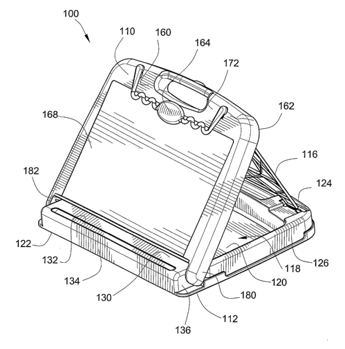
[0005] FIG. 1 is a front perspective view of an embodiment of a portable easel
configured in
the closed position with the upper housing portion overlaying the lower
housing portion.
[0006] FIG. 2 is a front perspective view of the easel configured in the
inclined position with
the upper housing portion supported by a stand at an inclined relation to the
lower housing
portion.
[0007] FIG. 3 is a rear perspective view of the easel configured in the
inclined position so as
to provide access to the storage compartment.
[0008] FIG. 4 is a top plan view of the easel configured in the closed
position.
[0009] ~ FIG. 5 is a rear elevational view of the easel configured in the
closed position.
[0010] FIG. 6 is a front elevational view of the easel configured in the
closed position.
[0011] FIG. 7 is a bottom plan view of fibe easel configured in the closed
position.
[0012] FIG. 8 is a first side elevational view of the easel configured in the
closed position.
[0013] FIG. 9 is a second side elevational view of the easel co~gured in the
closed position.
[0014] FIG. 10 is a front elevational view of the easel configured in the
inclined position
with the upper housing portion providing an inclined drawing surface.
[0015] FIG. 11 is a top plan view of the easel configured in the inclined
position with the
upper housing portion supported by the stand.
[0016] FIG. 12 is a rear elevational view of the easel configured in the
inclined position with
the upper housing portion supported by the stand.
2
CA 02528745 2005-12-08
WO 2005/046395 PCT/US2004/027867
[0017] FIG. 13 is a cross-sectional view of the easel configured in the
inclined position as
taken along lines 13-13 of FIG. 12.
[0018) FIG. 14 is a rear perspective view of the easel with the stand adjacent
to the inner
surface of the upper housing portion for facilitating configuration of the
easel into the closed
position.
DETAILED DESCRIPTION OF THE EMBODIMENTS
[0019] Now referring to the drawings, wherein like reference numbers refer to
like elements,
there is illustrated in FIGS. 1 and 2 an easel 100 designed in accordance with
the present
invention. The easel 100 includes a lower housing portion 112 adapted for
placement on top of a
table or the like and an upper housing portion 110 that is hingedly connected
to the lower
housing portion. Due to the hinged connection,, the upper and lower housing
portions 110, 112
can move between a multiplicity of positions with respect to each other. These
positions include,
as illustrated in FIGS. 1, 4, 5, 6, 7, 8, and 9 a closed position in which the
upper housing portion
I 10 overlays the lower housing portion 112 and, as illustrated in FIGS. 2, 3,
10, 1 l, 12, and 13 a
inclined position in which the upper housing portion is supported at an
inclined angle with
respect to the lower housing portion by a stand 116. The upper and lower
housing portions-are
preferably formed of a durable plastic material, such as polystyrene, ABS, or
the like.
[0020) When in the closed position, as illustrated in FIG. 1, the easel 100 is
configured as a
flat rectangular structure suitable for easy portability. As will be
appreciated from FIG. 2, when
the upper housing portion 110 is supported in the inclined position, a child
or artist can draw or
write on a sheet of paper or similar material placed adjacent to the upper
housing portion. To
store the drawing materials when not in use, as illustrated in FIGS. 2 and 3,
the lower housing
portion 112 includes a storage compartment 118 into which the drawing
materials can be placed.
As will be appreciated from FIG. 1, when the upper housing portion 110 is in
the closed position,
the storage compartment is substantially enclosed and any stored drawing
materials will be
contained therein. The easel 100 can therefore function as a carrying case
when the upper
housing portion 110 is in the closed position. To permit viewing of the
contents of the storage
compartment~l 18, the upper housing portion 110, or a section thereof, may be
made from
transparent.or translucent material.
3
CA 02528745 2005-12-08
WO 2005/046395 PCT/US2004/027867
(0021] As best illustrated in FIGS. 2, 3, and 13, the lower housing portion
112 includes a
generally flat bottom plane 120 upwards from which projects a front wall 122
and an opposing
rear wall 124. Additionally, a first sidewall 126 and an opposing second
sidewall 128,
substantially orthogonal to the front and rear walls 122, 124, also proj ect
upwards from the
bottom panel 120. As will be appreciated from FIG. 3, the front, rear, and
sidewalls 122, 124,
126, 128 are all molded together or otherwise j oined. Thus, the arrangement
of the front, rear,
and sidewalls 122, 124, 126,128 outlines the storage compartment 118 of the
lower housing .
portion 112. In an embodiment, to partition the storage compartment 118, a
plurality of partition
walls projecting upwards from,the bottom panel 120 may extend between and
among the front,
rear, and sidewalls 122, 124, 126, 128. Preferably the lower housing portion
112 is made of
plastic that is opaque.
[0022] Referring to FIGS. 2, 4, 11, and 13, the front wall 122 projects
upwards to form a top
surface 130 that is generally parallel to the bottom panel 120. To accommodate
writing utensils
such as crayons, pencils, and the like, there is formed in the top surface 130
an elongated groove
132. The groove 132 extends for a substantial portion of the length'of the
front wall 122.
Refernng to FIG. 2, the front wall 122 also includes a first side surface 136
that is indented
inwards with respect to the first sidewall 126. Referring to FIGS. 4 and 11, a
second side
surface 138, indented inwards with respect to~the second sidewall 128, is also
formed in the front
wall 122.
[0023] As illustrated in FIGS. 3 and 11, the rear wall 124 of the lower
housing~portion 112
also includes a central top surface 146 that is parallel to and offset upwards
from the bottom
panel 120. Disposed through the top surface 146 approximately midway between
the first and
second sidewalls 126, 128 is an oblong slot 148. Also, as best illustrated in
FIGS. 3, 11, and 12,
formed in the rear wall offset to either side of the slot 148 are-an elevated
or raised first and'
second side portions 150, 152, each of which includes an elongated indentation
154 formed into
it.
[0024] Refernng to FIG. 7, also included on the lower housing portion 112 on
the side of the
bottom panel 120 opposite the side from which the front, rear, and sidewalls
project, are a
plurality of footpads 156. The footpads 156, which can be part of the bottom
panel or can be
made of a resilient, foam-like material, are placed proximate to the four
corners of the easel 100.
As illustrated in FIG. 6, the footpads 156 preferably protrude slightly
downward from the lower
4
CA 02528745 2005-12-08
WO 2005/046395 PCT/US2004/027867
housing portion 112 to assist in preventing the easel 100 from moving or
slipping during use. -
Additionally, the footpads 156 help prevent the lower housing portion 112 from
scratching a
tabletop.
[0025] Referring to FIG. 2, the upper housing portion 110 of the easel 100
includes top panel
160 that is generally coextensive with the lower housing portion 112. As
illustrated in FIGS. 2
and 12, formed along the periphery of the top panel 160 is a peripheral wall
162 that projects
downward toward the lower housing portion 112. The peripheral wall 162 is
preferably a thin
walled structure that forms a smooth radius where it joins the top panel 160.
As will be
appreciated from FIGS. 1 and 4, when the upper housing portion 110 is in the
closed position,
the top panel 160 over lays the lower housing portion 112 and as will be
appreciated from FIGS.
1, 5, 8, and 9, the peripheral wall 162 extends over and conceals the rear
wall 124, first sidewall
126, and second sidewall 128. Accordingly, the storage compartment is
substantially enclosed
by the upper housing portion 110.
[0026] As illustrated in FIGS. 1, 2, 4, and 10, there can be formed into the
top panel 160 a
recessed pane 168. Preferably, as illustrated in FIGS. 4 and 10, the pane 168
is centrally located
with respect to the upper housing portion 110 and bordered by a first edge
170, a second edge
172, and third edge 174. Accordingly, the location of the pane 168 corresponds
to the location of
the storage compartment while the edges 170, 172, 174 correspond to the rear
wall and sidewalls
of the lower housing portion.
[0027] To permit viewing of the contents of the storage compartment when the
upper
housing portion 110 is in the closed position, ~in accordance with an aspect
of the present
invention, the upper housing portion 110. or a section thereof is made from
transparent or
translucent material and the lower housing portion 112 may be made from an
opaque material.
The transparent or translucent material permits the viewing of the contents of
the storage
compartment 118. In another embodiment, the lower housing portion 112 may be
made from a
transparent or translucent material and the upper housing portion 110 may be
made from an
opaque material. In an additional embodiment, the upper and lower housing
portions 112, 114
may be made from a transparent or translucent material. In a further
embodiment, the pane 168
may be made from a transparent or translucent material and the edges 170,172,
174 may be
made from an opaque material.
CA 02528745 2005-12-08
WO 2005/046395 PCT/US2004/027867
[0028] To facilitate moving the upper housing portion 110 between the closed
and inclined
positions, as illustrated in FIGS. 1 and 2, the upper housing portion is
hingedly connected to the
front wall 122. Specifically the upper housing portion 110 includes a first
flange member 180
and a second flange member 182 proximate to the peripheral wall 162 that
extend beyond the
front most edge of the top panel 160. When the easel 100 is properly
assembled, as illustrated in
FIGS. 1, 2, 4, and 11, the first and second flange members 180, 182 are
located proximate to the
indented first and second side surfaces 136, 138,of the front wall 122.
Referring to FIG. 13, a
hole 186 disposed in the side surface 126 can receive a pin 184 projecting
from the flange 180.
As will be readily understood by those of skill in the art, the pin 184 can
rotate within the Bole
186 allowing the upper housing portion 110~to articulate with respect to the
lower housing
portion 112.
[0029] When the upper housing portion 110 is in the inclined position, as
illustrated in FIG.
2, the pane 168 is sloped with respect to the lower housing portion 112 and
forms an inclined
support surface adjacent to which a sheet of paper or similar material can be
placed for a child or
artist to draw upon. To retain the sheet over the pane 168, a spring clip 164
can be included on
the second or top most edge 172. In a manner well known to those of skill in
the art, the spring
clip 164 urges itself against the pane 168 to trap an edge of the drawing
sheet.
[0030] When supporting the upper housing portion 110 in the inclined position,
as illustrated
in FIGS. 3 and 12, the stand 116 extends between the inner surface of the
second or top most
edge 172 to the rear wall 124 of the lower housing portion 112. The stand 116
is generally flat
or planer in construction and includes a first side member 190 and a spaced
apart second side
member 192 with a transverse support member 194 extending between them. As
best illustrated
in FIGS. 11, 12, and 13, the proximal end of each side member is formed with a
generally
cylindrical lug 196 while the opposing distal end of each side member is
likewise formed with a
generally cylindrical lug 198. As illustrated in FIGS. 12 and 13, to attach
the stand 116 to the
upper housing portion 110, the inner surface of the top most edge 172 includes
slotted receiving
members 202 that can pivotally engage each of the proximal lugs 196.
[0031] Referring to FIG. 3, 11, and 13, to attach the stand 116 to the rear
wall,124, the distal
lugs 198 can be releasably retained iri indentations 154 formed into the
elevated first and second
raised portions 150, 152. Accordingly, it will be appreciated that the spacing
between the first
and second side members 190, 192 of the stand 116 corresponds to the first and
second raised
6
CA 02528745 2005-12-08
WO 2005/046395 PCT/US2004/027867
portions 150,152. To facilitate the releasable nature of lug - indentation
engagement, the
indentations 154 each can include a flexible holding portion 158 proximate to
the upper surface
of the first and second raised portions 150, 152 that preferably extend a
portion of the length of
the indentations. When received in the indentation 154, the holding portion
158 partially
encompasses or extends over the lug 198 thereby retaining the stand to the
rear wall 124.
However, the holding portion 158 can deflect under an applied, moderate force
thereby releasing
the lug 198 when, for instance, the stand 116 is pulled upwards with respect
to the rear wall 124.
The holding portion 158 similarly deflects to initially receive the lug 198
into the indentation 154
when the stand 116 is properly pressed down onto the rear wall 124. On account
of this ' ~ .
construction, the upper housing portion 110 can be easily configured into the
inclined position by
a child without the use of tools.
j0032] To accommodate the stand 116 when the upper housing portion 110 is in
the closed
position, as illustrated in FIG. 14, the distal lugs 198 can be removed from
the indentations 154
and the stand can be pivotally swung adjacent to the inner surface of the
upper housing portion
110. Swinging movement of the stand 116 is enabled by the pivotal engagement
of the slotted
receiving members 202 and the proximal lugs 196 described above. As will be
appreciated,
when the upper housing portion 110 is placed into the closed position, the
stand 116 is
sandwiched between the upper and lower housing portions 110, 112. In an
embodiment, when
the upper housing portion 110 is in the closed position, the proximal lugs 196
can be releasably
received in the indentations 154 formed in the rear wall 124 in a manner
similar to the one
described above.
[0033] As will be appreciated from FIG. 14, in some embodiments~when the stand
116 is
adjacent to the inner surface of the upper housing portion 110, the stand will
obstruct the.view
through the upper housing portion of the storage compartment '118. To mitigate
the obstruction,
in these embodiments it is desirable to manufacture the stand 116 from the
same transparent or
translucent material as the upper housing portion 110. In other embodiments,
the stand 116 may
be designed to not obscure the storage compartment 118.
[0034] Referring to FIGS. 4 and 5, to facilitate moving the upper housing
portion .l 10 to the
opened position, a notch 204 is, formed in the outer surface of the rear wall
124 and an aligned
protrusion 206 is formed on the peripheral wall 162. As will be appreciated, a
child's finger tip
can use the protrusion 206 to move the upper housing portion 110 open.
Refernng to FIG. 4, to
7
CA 02528745 2005-12-08
WO 2005/046395 PCT/US2004/027867
facilitate easy handling of the easel 100, there is also formed in the second
or top edge 172
approximately in the middle of the upper housing portion a second oblong slot
178. Referring to
FIGS. 4 and 7, when the upper housing portion 110 is in the closed position
overlaying the lower
housing portion 112, the second slot 178 aligns with the first slot 148 to
provide a handle for
carrying the closed easel 100, thus facilitating the easel's functioning as a
carrying case.
[0035] Thus, the present invention provides a portable easel with a viewable
storage
compartment into which drawing materials can be stored. The easel can be
folded into an
opened position in which the easel provides an inclined surface against which
a sheet of drawing
material can be placed for a child to draw on and a closed position in which
the storage container
is fully enclosed. To permit viewing of the contents of the storage container,
a portion of the
easel is manufactured from transparent or translucent material.
[0036] All references, including publications, patent applications,
and.patents, cited herein
are hereby incorporated by reference to the same extent as if each reference
were, individually
and specifically indicated to be incorporated by reference and were set forth
in its entirety herein.
[0037] The use of the terms "a" and "an" and "the" and similar referents in
the context of
describing the invention (especially in the context of the following claims)
are to be construed to
cover both the singular and the plural, unless otherwise indicated herein or
clearly contradicted
by context. Recitation of ranges of values herein are merely intended to serve
as a shorthand
method~of referring individually to each separate value falling within the
range, unless otherwise,
indicated herein, and each separate value is incorporated into the
specification as if it were
individually recited herein. All methods described herein can be performed in
any suitable order
unless otherwise indicated herein or otherwise clearly contradicted by
context. The use of any
and all examples, or exemplary language (e.g., "such as") provided herein, is
intended merely to
better illuminate the invention and does not pose a limitation on the scope of
the invention unless
otherwise claimed. No language in the specification should be construed as
indicating any non-
claimed element as essential to the practice of the invention.
[0038] Preferred embodiments of this invention are described herein, including
the best
mode known to the inventors for carrying out the invention. Of course,
variations of those
preferred embodiments would become apparent to those of ordinary skill in the
art upon reading
the foregoing description. The inventors expect skilled artisans to employ
such variations as
appropriate, and the inventors intend for the invention to be practiced
otherwise than as
8
CA 02528745 2005-12-08
WO 2005/046395 PCT/US2004/027867
specifically described herein. Accordingly, this invention includes all
modifications and
equivalents of the subject matter recited in the claims appended hereto as
permitted by applicable
law. Moreover, any combination of the above-described elements in all possible
variations
thereof is encompassed by the invention unless otherwise indicated herein or
otherwise clearly
contradicted by context.
9