Note: Descriptions are shown in the official language in which they were submitted.
CA 02528877 2008-03-13
SELF-LOCHING LINEAR ADJUSTMENT MECHANISM
TECHNICAL FIELD
The present invention relates generally to positioning devices and, more
particularly, to a self-
locking linear adjustment mechanism.
BACKGROUND ART
Positioning devices forpreciselyadjusting longitudinal distances between two
articles are known
inthe art. The operation ofmany ofthese devices involve a number oftime
consuming steps, result in
mechanical wear, and result in costly construction.
Aneedexistsforapositioningdevicewhichprecisely
adjusts the longitudinal distance between two articles with a simple,
reliable, and easily accessible locking
provision.
The related art is represented by the following references of interest.
U.S. Patent Publication No. 2001/0009632 Al, published on July 26, 2001, and
U.S.
PatentNo. 6,331,091 B2, issued on December 18,2001 for GaryA. Cross, describe
an axle made-up
of a left and right axle halves which axially engage to form a completed axle
assembly for supporting a
roller skate wheel or other rotating member. The Cross application and patent
do not suggest a self-
locking linear adjustment mechanism according to the claimed invention.
U.S. Patent Publication No. 2002/0006310 Al, published on January 17, 2002,
and
U.S. Patent No. 6,499,908 B2, issued on December 31, 2002, for Udo Hauptmann
et al., describe a
loeking system for a cylindrical sha$, which, dynamically, canbe stressed
strongly in the axial direction and
can be easily mounted and dismounted. The Hauptmann et al. application and
patent do not suggest a self-
locking linear adiustment mechanism according to the claimed invention.
U.S. Patent Publication No. 2002/0071719 Al, published on June 13, 2002 for
Daniel L_ Moore, describes a control rod for an aircraft actuator system. The
Moore application does not
suggest a self-locking linear adjustment mechanism according to the claimed
invention.
U.S. Patent Publication No. 2002/0197105 Al, published on December 26, 2002
for Jung-Chang Chiang, describes a connection apparatus for an artificial
model which can be configured
to connect with any spot of the thigh and obtain a curve dividing line
suchtha.t the dividing line maynot
expose unpleasantly at the time ofexhibiting swimming suit or underwear. The
Chiang application does
not suggest a self-locking linear adjustment mechanism according to the
claimed invention.
U.S. PatentNo. 2,814,324, issued onNovember 26,1957 to Ira Shur, describes a
nut assembly
in a quick acting nut and bolt fastener that enables full fastening and
unfastening effect to be attained with
only limited turning of the bolt in a proper direction and in which the bolt
may be fully fastened and
unfastened from the bolt side of the fastener. The Shur patent does not
suggest a self-locking linear
adjustment mechanism according to the claimed invention.
CA 02528877 2005-12-01
WO 2005/002781 PCT/US2004/020769
2
U.S. Patent No. 3,643,523, issued on February 22, 1972 to John Mihaila,
describes a knob
assemblyparticularly adaptable to a control device form moving the core of
apush-pull cable with respect
to the casing thereof in gross amounts, and, selectively, in accurately fine,
or vernier, increments. The
Mihaila patent does not suggest a self-locking linear adjustment mechanism
according to the claimed
invention.
U.S. Patent No. 3,667,313, issued on June 6, 1972 to Don L. Young, Jr.,
describes a flexible
remote control with spaced ball bearings for transmittingpush and pull forces.
The Young, Jr. patent does
not suggest a self-locking linear adjustment mechanism according to the
claimed invention.
U.S. Patent No. 3,946,984, issued on March 30, 1976 to Jean G. Sutter,
describes a motor-
driven control device for a valve rod. The Sutter patent does not suggest a
self-locking linear adjustment
mechanism according to the claimed invention.
U.S. PatentNo. 3,992,120, issued onNovember 16,1976 to F1ori,anB. Recker,
describes a shaft
coupling apparatus for connecting one shaft to another shaft. The Recker
patent and application does not
suggest a self-locking linear adjustment mechanism according to the claimed
invention.
U.S. Patent No. 4,238,974, issued on Deceinber 16, 1980 to Harry E. Fawcett,
describes a
flexure-limiting tubular ball and socket universal j oint device that
protectively supports and guides the inner
or center cable of a coaxial push-pull cable assemblywhile providing a seal
effective to exclude dirtand
moisture in the variously deflected positions ofthe inner member and its load-
connected extension rod
fitting. The Fawcett patent does not suggest a self-locking linear adjustment
mechanism according to the
claimed invention.
U.S. Patent No. 4,378,187, issued on March 29,1983 to Robert L. Fullerton,
describes a quick
acting nut assembly for selectively engaging a threaded member. The Fullerton
patent does not suggest
a self-locking linear adjustment mechanism according to the claimed invention.
U.S. Patent No. 4,531,872, issued on July 30,1985 to Horst Warkotsh, describes
a quick action
tensioning nut for fastening a wheel to the mounting shaft of a wheel
balancing machine. The Warkotsh
patent does not suggest a self-locking linear adjustment mechanism according
to the claimed invention.
U.S. Patent No. 4,569,242, issued on February 11, 1986 to Anny Hu, describes a
rapid
advancing and clamping mechanism for a clamping device. The Hupatent does not
suggest a self-locking
linear adjustment mechanism according to the claimed invention.
U.S. Patent No. 4,603,998, issued on August 5,1986 to Helmu Bober et al.,
describes a shaft
connecting mechanism for securing a slip-on hub to the power takeoff shaft of
a tractor. The Bober et al.
patent does not suggest a self-locking linear adjustment mechanism according
to the claimed invention.
U.S. PatentNo. 4,618,300, issued on October 21, 1986 to Eickhart Goebel,
describes a quick-
clamping nut for permitting rapid engagement with an externally threaded
member with a minimum of
turning to lock a first member to a second member. The Goebel patent does not
suggest a self-locking
linear adjustment mechanism according to the claimed invention.
U.S. Patent No. 4,646,546, issued on March 3, 1987 to Ashley P. Smith,
describes a locking
device forreleasablyretainulg apluralityofyam.packages beneath apressure plate
on averticallydisposed
CA 02528877 2005-12-01
WO 2005/002781 PCT/US2004/020769
3
spindle. The Smith patent does not suggest a self-locking linear adjustment
mechanism according to the
claimed invention.
U.S. Patent No. 4,684,284, issued on August 4,1987 to Charles D. Bradley, Jr.,
describes an
anti-rotation lock assembly. The Bradley, Jr. patent does not suggest a self-
locking linear adjustment
mechanism according to the claimed invention.
U.S. Patent Nos. 4,696,203 and 4,773,150, issued on September 29,1987 and
September 27,
1998, respectively, to Ted W. Gregory, describe apush-pull vernier control
assenlbly and amethod of
manufacture thereof for regulating the operating speed of power equipment. The
Gregorypatents do not
suggest a self-locking linear adjustment mechanism according to the claimed
invention.
U.S. Patent No. 4,756,654, issued on July 12,1988 to Melvyn J.L. Clough,
describes a quick
action tensioning nut for fastening a wheel to the mounting shaft of a wheel
balancing machine. The
Warkotsh patent does not suggest a self-locking linear adjustment mechanism
according to the claimed
invention.
U.S. Patent No. 4,764,071, issued on August 16,1988 to Ventura A. Lawrence et
al., describes
a quick action end-to-end fastener for coupling a pair of reinforcing rods end-
to-end. The Lawrence et
al. patent does not suggest a self-locking linear adjustment mechanism
according to the claimed invention.
U.S. Patent No. 4,790,580, issued on December 13, 1988 to Leonello Casilio,
describes a
latching mechanism for providing a locking support for an article
whichperiodicallyrequires to be moved
from a rest position to a stable elevated position. The Casilio patent does
not suggest a self-locking linear
adjustment mechanism according to the claimed invention.
U.S. Patent No. 4,792,255, issued on Decem.ber 20,1988 to James McArthur et
al., describes
an adjustable coupling assembly which allows an exercising member to be locked
and secured in a
multitude ofpositions about a shaft while still permitting the removal of the
exercising member. The
McArthur et al. patent does not suggest a self-locking linear adjustment
mechanism according to the
claimed invention.
U.S. PatentNo. 4,813,810, issued onMarch21,1989 to Tsunehiko Suzuki, describes
acoupling
device in which a shaft or pipe is coupled to a boss member in which balls,
disposed in radial holes in the
boss, engage a groove on the shaft or pipe. The Suzuki patent does not suggest
a self-locking linear
adjustment mechanism according to the claimed invention.
U.S. Patent No. 4,919,119, issued on April 24,1990 to Ulf Jonsson et al.,
describes an external
fixation device for the fixation of abroken j oint. The Jonsson et al. patent
does not suggest a self-loclcing
linear adjustment mechanism according to the claimed invention.
U.S. Patent No. 4,974,888, issued on December 4, 1990 to Spencer L. Childers,
describes a
fastening apparatus operable to secure a pair of work objects to each other.
The Childers patent does
not suggest a self-locking linear adjustment mechanism according to the
claimed invention.
U.S. Patent No. 5,081,811, issued on January 21, 1992 to Kensuke Sasaki,
describes a self-
locking nut mechanism operable to be mounted on abolt element to secure
structural members together.
CA 02528877 2005-12-01
WO 2005/002781 PCT/US2004/020769
4
The Sasaki patent does not suggest a self-locking linear adjustment mechanism
according to the claimed
invention.
U.S. Patent No. 5,105,554, issued on Apri121, 1992 to Urs Schnyder et al.,
describes an
instrument for measuring the dimensions of a rigid object. The Schnyder et al.
patent does not suggest a
self-locking linear adjustment mechanism according to the claimed invention.
U.S. Patent No. 5,233,892, issued on August 10, 1993 to Peter M. Roberts,
describes a quick
release mechanism for tools such as socket wrenches. The Roberts patent does
not suggest a self-locking
linear adjustment mechanism according to the claimed invention.
U.S. Patent Nos. 5,258,772 and 5,670,968, issued on November 2, 1993 and
September 23,
1997, respectively, to Masayuki Inanaga et al., describe an antenna device
equipped with a retractable
antenna as a main antenna that is capable of maintaining a receiver function
even when the flexible antenna
is retracted. The Inanaga et al. patents do not suggest a self-locking linear
adjustment mechanism
according to the claimed invention.
U.S. Patent No. 5,306,979, issued on Apri126, 1994 to John F. Schwarz, Jr.,
describes a
multiplexing incremental linear actuator system for linearly outputting an
output member in the fonn of a
mechanical control wire. The Schwarz. Jr. patent does not suggest a self-
locking linear adjustment
mechanism according to the claimed invention.
U.S. Patent No. 5,335,949, issued on August 9, 1994 to Horst Maury et al.,
describes a
telescopic positioning device. The Maury et al. patent does not suggest a self-
locking linear adjustment
mechanism according to the claimed invention.
U.S. Patent No. 5,431,540, issued on July 11, 1995 to Leonard J. Doolin et
al., describes a main
rotor pitch control rod subassembly for a helicopter main rotor assembly. The
Doolin et al. patent does
not suggest a self-locking linear adjustment mechanism according to the
claimed invention.
U.S. Patent No. 5,538,245, issued on July 23,1996 to Donald D. Moore,
describes a golf club
with an adjustable head. The Moore patent does not suggest a self-locking
linear adjustment mechanism
according to the claimed invention. I
U.S. Patent No. 5,573,290, issued on November 12, 1996 to Edward J. Smith,
describes a
retaining device for locking pistons that have retractable sliding arms. The
Smith patent does not suggest
a self-locking linear adjustment mechanism according to the claimed invention.
U.S. Patent No. 5,800,108, issued on September 1, 1998 to Eric F. Cabahug,
describes an
apparatus for rapidly engaging and disengaging threaded coupling members. The
Cabahug patent does
not suggest a self-locking linear adjustment mechanism according to the
claimed invention.
U.S. Patent No. 5,845,898, issued on December 8, 1998, and European Patent
Application
Publication No. 838,600 Al, published on August 12, 1998, for Werner Halder et
al., describe a
self-adjusting ball-lock pin for holding together two objects with aligned
holes. The Halder et al. patent
and European'600 application do not suggest a self-locking linear adj ustment
mechanism according to the
claimed invention.
CA 02528877 2008-03-13
U.S. Patent No. 5,846,042, issued on December 8, 1998 to Peter Iannuzzi,
describes a
fastener/shaft locking and adj ustment apparatus and locking system which
preciselypositions, positively
locks, and avoids slippage of a positive loclcingnut along an elongated
element. TheIannuzza patent does
not suggest a self-locking linear adjustment mechanism according to the
claimed invention.
5 U.S. Patent No. 6,158,930, issued on December 12, 2000 to Mark A. Etter,
describes a
positioning system adapted for guiding a cutting tool for a portable machine
tool with respect to a
workpiece for the purpose ofmachuung the workpiece. The Etter patent does not
suggest a self-locking
linear adjustment mechanism according to the claimed invention.
U.S. Patent No. 6,361,260131, issued on March 26,2002 to Wendell E.
Schirrmacher, describes
a quick action tensioning nut for fastening a wheel to the mounting shaft of a
wheel balancing machine. The
Schinmacher patent does not suggest a self-locking linear adjustment mechanism
according to the claimed
invention.
U.S. Patent No. 6,367,341 B 1, issued on April 9, 2002 to Howard L. Sleeper et
al., describes
a slidable fixture positioner for positioning an object in a remote location
with ahigh degree ofprecision.
The Sleeper et al. patent does not suggest a self-locking linear adjustment
mechanism according to the
claimed invention.
U.S. Patent No. 6,485,214 B2, issued on November 26, 2002 to Albrecht P.
Schill, describes
a coupling device, in combination with two coupling members, for
coaxiallycoupling the first coupling
meniber to the second coupling member. The Schill patent does not suggest a
self-locking linear
adjustment mechanism according to the claimed invention.
U.S. Patent No. 6,511,100 B 1, issued on January 28, 2003 to Pascal Le
Clinche, describes a
ball-bearing coupler. The Le Clinche patent does not suggest a self-locking
linear adj ustment mechanism
according to the claimed invention.
U.S. Patent No. 6,523,411 B2, issued on February 25, 2003 to Jack Lee,
describes a switch
device ofa socket wrench extension. The Lee patent does not suggest a self-
locking linear adjustment
mechanism according to the claimed invention.
U.S. Patent No. 6,540,426 B2, issued on April 1, 2003 to a Richard A. Cloyd et
al., describes
a passive ball capture joint. The Cloyd et al. patent does not suggest a self-
locking linear adjustment
mechanism according to the claimed invention.
Germany Patent Publication Nos. 3,739,710 Cl and 3,839,663 Al, published on
January 26, 1989 and June 15, 1989, respectively, describe a device for
connecting two tool parts. The
Geamany'710 and'663 applications do not suggest a self-locking linear
adjustment mechanism according
to the claimed invention.
Germany Patent Publication Nos. 4,000,424 Al and 4,000,424 C1, published on
July
11,1991, describe clamping device for a rotating body. The Germany'424
applications do not suggest
a self-locking linear adjustment mechanism according to the claimed invention.
CA 02528877 2008-03-13
6
Great Britain Patent Publication No. 2,279,693 A, published on January 11,
1995,
describes a ball locking device. The Great Britain'693 application does not
suggest a self-loclcing linear
adjustment mechanism according to the claimed invention.
Germany Patent Publication No. 19,701,365 Al, published on July 23, 1998,
describes a device for releasably attaching a component to a carrier. The
Germany'710 application does
not suggest a self-locking linear adjustment mechanism according to the
claimed invention.
France Patent Publication No. 2,812,923 Al, published on February 15, 2002,
describes a device including a rigid rod able to translate and rotate one end
of whichpenetrates a recess
of a piston. The France'923 application does not suggest a self-locking linear
adjustment mechanism
according to the claimed invention.
None of the above inventions and patents, taken either singularly or in
combination, is seen to
describe the instant invention as claimed. Thus a self-loclcing linear
adjustment mechanism solving the
aforementioned problems is desired.
DISCLOSURE OF THE INVENTION
The present invention is a self-locking linear adjustment mechanism. The
mechanism includes a
locking tumbler, an adjustment vernier, two end adapters, two roll pins, and
two precision balls. Also
included are two locking skirts, two springs, two loclcing splines, two index
pins, and two guide shafts.
The self-locking linear adjustment mechanism has a dual function self-locking
feature.
BRIEF DESCRIPTION OF THE DRAWINGS
Fig. l is a side perspectiveview of an example ofa self-locking linear
adjustment mechanism in
the form of a complete rod assembly according to the present invention.
Fig. 2 is a side perspective view of another example ofa self-loclcing linear
adjustment mechanism
in the form of a cartridge assembly according to the present invention.
Fig. 3 is a cross-sectional side perspective view ofthe self-locking
linearadjustrnentmechanism
example shown in Fig. 2.
Fig. 4 is an exploded side perspective view ofthe self-locking linear
adjustment mechanism
example shown in Fig. 2.
Fig. 5 is a top view of the self-locking linear adjustment mechanism exaniple
shown in Fig. 2.
Fig. 6 is a cross-sectional view along line A-A of the self-locking linear
adjustnient mechanism
example shown in Fig. 5.
Fig. 7 is a cross-sectional view along line B-B of the self-locking linear
adjustment mechanism
example shown in Fig. 6.
Fig. 8 is a cross-sectional view along line C-C of the self-locking linear
adjustment mechanism
example shown in Fig. 5.
CA 02528877 2005-12-01
WO 2005/002781 PCT/US2004/020769
7
Fig. 9 is a cross-sectional view along line D-D ofthe self-locking linear
adjustment mechanism
example shown in Fig. 6.
Fig.10 is a cross-sectional view along line E-E ofthe self-locking linear
adjustment mechanism
example shown in Fig. 6.
Fig. 11 is a cross-sectional view along line F-F ofthe self-locking linear
adjustment mechanism
example shown in Fig. 6.
Similarreference characters denote corresponding features consistently
throughout the attached
drawings.
BEST MODES FOR CARRYING OUT THE INVENTION
The present invention is a self-locking linear adjustment mechanism. The self-
locking linear
adjustment mechanism is an assembly that maybe configured in the form of a
complete rod assembly or
a cartridge assembly. The self-locking linear adjustment mechanism in the form
of a cartridge assembly
includes a self-locking linear adjustment mechanism including a locking
tumbler, an adjustment vernier, two
end adapters, two roll pins, two precision balls, two locking skirts, two
springs, two locking splines, two
index pins, and two guide shafts, wherein the self-locking linear adjustment
mechanism has a dual function
self-locking feature.
The locking tumbler is a longitudinally extending member that extends for
apredeternlined distance
and has two opposing ends. Each end has a recess defined therein. The locking
tumbler includes two
opposing pockets that may be spherically configured to enable placement and
retention of the two
precision balls. The balls are positioned not to be in contact with the two
faces the locking splines when
the self-locking linear adjustment mechanism is in the locked position. The
balls are guided by the minor
diameter of the internal spline ofthe adjustment vernier. The locking tumbler
is secured in place axiallyby
2 5 the use of two standard roll pins that tangentially engage grooves in the
locking tumbler.
The roll pins each extend for a predetermined length and have a predetermined
diameter. The roll
pins are configured for securing the locking tum.bler axially in place by
tangentially engaging grooves in the
locking tumbler, and corresponding holes in the adjustment vernier.
The adjustment vernier includes a central member with two tubular members
extending
longitudinally away from the central member in opposing directions. Each
tubular member includes
proximal and distal ends relative to the central member of the adjustment
vernier, as well as a plurality of
slits equally spaced about the associated tubular member. The equally spaced
slits extend for a
predetermined distance from the distal end to the proximal end of the
associated tubular member. Each
tubular member is also externally threaded in apredetermined manner for a
predetermined distance from
the distal end to the proximal end of the associated tubular member. Each
tubular member has a
predetermined inner circumference at the proximal end that is less than a
predetermined inner
circumference at the distal end of the tubular member.
CA 02528877 2005-12-01
WO 2005/002781 PCT/US2004/020769
8
Each end adapter longitudinally extends for a predetermined distance, and
includes an inner end
and an outer end. The inner end of the end adapter is configured for engaging
the distal end of a
corresponding tubular member of the adjustment vernier, and the outer end of
the end adapter is
configured for engaging another element via threading or the like. Between the
inner end and the outer end
of each end adapter a passage inhibitor is provided that includes a hole
defined therein configured in the
form of a'D' or the like for allowing a correspondingly configured guide
shafts to pass therethrough. The
inner end ofthe end adapter is configured with inner threading in accordance
with the extemal threading
on the corresponding tubular member of the adjustment vernier.
The loclcing skirts are configured for fitting around an assembly of loclcing
splines, index pins, and
guide shafts. The locking splines, index pins, and guide shafts maybe
configured as a single combined
component, wherein one of each maybe used inplace of the two sets ofthe three
separate components.
The locking skirts extend for a predetermined length and have an inner end and
an outer end. The inner
end is configured for being placedproximate the central member of the
adjustment vernier. The outer end
is configured for engaging the distal end ramp of the corresponding tubular
member ofthe adjustment
vernier. The locking skirts have a raised spherical shoulder on their outside
diameters at the outer ends.
The spherical shoulder ofthe locking skirts engage the conical lead in distal
end ramps of tubular members
ofthe adjustment vernierproviding auniform radial pressure to expand the
slotted ends ofthe adjustment
vernier when the lock is engaged.
The springs are configured for biasing apart the inner end of a locking skirt
and an inner end of a
corresponding end adapter. The ends of each spring bear against an internal
shoulder on an end adapter
on one end, and against an internal shoulder of a locking skirt at the
opposing end.
Each locking spline extends for a predetermined length and has an inner end
and an outer end.
The inner end of each locking spline has a plurality of external splines
configured for engaging with the
internal splines at the proximal end of the tubular elements of the adjustment
vernier. Each index pin
extends for a predetermined length and has a predetermined diameter. Each
index pin is configured for
securing the loclcing spline and the guide shafts together. The guide shafts
have a predetermined length and
are cross drilled to receive the index pins that secure the locking splines
and the guide shafts together. The
locking skirts also serve to capture the index pins in place as they are
installed tluough the locking splines
and the guide shafts.
The invention disclosed herein is, of course, susceptible of embodiment in
many different forms.
Shown in the drawings and described herein below in detail are preferred
embodiments of the invention.
It is to be understood, however, that the present disclosure is an
exemplification ofthe principles of the
invention and does not limit the invention to the illustrated embodiments.
Referring to the drawings, Fig.1 shows an example of a self-locking linear
adjustment mechanism
according to the present invention in the fonn of a complete rod assembly 10.
The self-locking linear
adjustxnent mechanism in the form of a complete rod assembly 10 enables users
to provide a control rod
as a single complete assembly. The self-locking linear adj ustment mechanism
10 in the form of a complete
rod assembly includes a locking tumbler 12, an adjustment vernier 14 with two
oppositely extending
CA 02528877 2005-12-01
WO 2005/002781 PCT/US2004/020769
9
tubular members 15, and two end adapters 16 appropriately configured for being
secured with a connector
ending 20 via rivets 18.
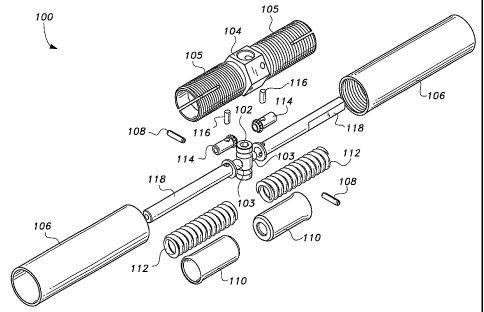
Ilgs. 2-11 show examples of amore generic self-locking linear adjustment
mechanism according
to the present invention in the form of a cartridge assembly 100. The self-
locking linear adjustment
mechanism 100 in the form of a cartridge assembly enables a user to adapt the
single part adjustment
mechanism 100 to connector endings having particular ending configurations
according to the desires of
the user. The self-locking linear adjustment mechanism 100 in the form of a
cartridge assembly includes
a locking tumbler 102, an adjustment vernier 104, two end adapters 106, two
roll pins 108, two precision
balls 103, two locking skirts 110, two springs 112, two locking splines 114,
two index pins 116, and two
guide shafts 118.
The locking tumbler 102 is a longitudinally extending member that extends for
a predetermined
distance and has two opposing ends. Each end has a recess defined therein.
Preferably the recess at
either end is configured in form of apolygon, such as ahexagon or the like.
For example, configuring the
polygon of the locking tumbler 102 in the form of a hexagon enables a user to
readily actuate the locking
tumbler 102 with a corresponding size of Allen wrench. The locking tumbler 102
includes two opposing
pockets that maybe spherically configured, or the like, to enable placement
and retention oftwo precision
balls 103, such as steel balls or the like. The precision balls 103 are
positioned not to be in contact with
the two faces the locking splines 114 when the self-locking linear adjustment
mechanism 100 is in the
lockedposition. The precision balls 103
areguidedbytheminordiameteroftheinternalsplineofthe
adjustment vernier 102. The locking tumbler 102 is secured in place axiallyby
the use of two standard
roll pins 108 that tangentially engage grooves in the locking tumbler 102.
The roll pins 108 each extend for a predetermined length and have a
predetermined diameter. The
roll pins 108 are configured for securing the locking tumbler 102 axially in
place by tangentially engaging
grooves in the locking tumbler 102 and corresponding holes in the adjustment
vernier 104.
The adjustment vernier 104 includes a central member with two tubular members
105 extending
longitudinally away from the central member in opposing directions. Each
tubular member 105 includes
proximal and distal ends relative to the central member of the adjustment
vernier 104, as well as a plurality
of slits equally spaced about the associated tubular member. The equally
spaced slits extend for a
predetermined distance from the distal end to the proximal end ofthe
associated tubularmember 105.
Each tubular member 105 is also externally threaded in a predetermined manner
for a predetermined
distance from the distal end to the proximal end ofthe associated tubular
member 105. Preferably, the
tubular members 105 are externally threaded with right hand threads of unequal
pitch when a vemier style
adjustment is desired, such as a vernier style 14RH/20RH thread pitch ratio to
provide a lockable
increment of 0.00077 inch (0.020 mm) and a range of+/- 0.100 inch (3 mm).
Alternatively, one tubular
member 105 may be configured with a right hand thread and the other tubular
member 105 may be
configured with a left hand thread of equal pitch when a coarser turnbuckle
style adjustment is desired,
such as a 20RH/20LH turnbuckle style thread pitch ratio. Each tubular member
105 has a predetermined
inner circumference at the proximal end that is less than a predetermined
inner circumference at the distal
CA 02528877 2005-12-01
WO 2005/002781 PCT/US2004/020769
end of the tubular member 105. Preferably, the predetermined inner
circumference at the distal end
reduces in value quickly as distance passes from the distal end to the
proximal end ofthe tubular member
105, e. g., in the form of a distal end ramp or the like, and then the inner
circumference reaches a value that
remains generally consistent for the majority of the length of the tubular
element 105.
5 Each end adapter 1061ongitudinally extends for a predetermined distance, and
includes an inner
end and an outer end. The inner end of the end adapter 106 is configured for
engaging the distal end of
a corresponding tubular member of the adjustment vernier 104, and the outer
end of the end adapter 106
is configured for engaging another element via threading or the like. Between
the inner end and the outer
end of eacli end adapter 106 a passage inhibitor is provided that includes a
hole defined therein configured
10 in the form of a'D' or the like for allowing a correspondingly configured
guide shafts 118 to pass
therethrough. The inner end of the end adapter 106 is configured with inner
threading in accordance with
the external threading on the corresponding tubular member 105 of the
adjustment vernier 104. For
example, ifthe external threading on one tubular member 105 of the adjustment
vernier 104 were with right
hand threads of one pitch, such as 14RH or the like, the internal threading of
the corresponding end
adapter 106 will be threaded accordingly in a vernier style, e.g., 14RH, in
accordance with the desires of
the user. Alternatively, if the external threading on one tubular member 105
ofthe adjustment vernier 104
were with right hand threads of one pitch, such as 20RH or the like, the
internal threading of the
corresponding end adapter 106 may be threaded accordingly in a tumbuckle
style, e.g., 20LH.
The locking skirts 110 are configured for fitting around an assembly of
locking splines 114, index
pins 116, and guide shafts 118. The locking skirts 110 extend for a
predetermined length and have an
inner end and an outer end. The inner end is configured for being placed
proximate the central member
of the adjustment vernier 104. The outer end is configured for engaging the
distal end ramp of the
corresponding tubular member of the adjustment vernier 104. The locking skirts
110 have a raised
spherical shoulder on their outside diameters at the outer ends. The spherical
shoulder ofthe locking skirts
110 engage the conical lead in distal end ramps of the tubular members of the
adjustment vernier 104
providing a uniform radial pressure to expand the slotted ends of the
adjustment vernier 104 when the lock
is engaged.
The springs 112 are configured for biasing apart the inner end of a locking
skirt 110 and an inner
end of a corresponding end adapter 106. The ends of each spring 112 bear
against an iriternal shoulder
on an end adapter 106 on one end and against an internal shoulder of a locking
skirt 110 at the opposite
end. When in the locked position the springs 112 force the engagement of the
internal splines of the
adjustment vernier 104 and the external splines of the locking splines 114.
The mechanism does not
bottom at the spline engagement. The spring load also simultaneously drives
the locking skirts 110 into
the conical lead in distal end ramps ofthe tubular members 105 ofthe
adjustment vernier 104. This action
expands the slotted ends of the tubular members 105 of the adjustment vernier
104 using this mechanical
advantage to force a tight engagement of its external threads with the
internal threads of the rod end
adapters thereby eliminating all axial free play in both directions that may
exist due to manufacturing
tolerances within the threaded engagement. This constitutes the dual function
locking features ofthis
CA 02528877 2005-12-01
WO 2005/002781 PCT/US2004/020769
11
mechanism, positive rotational locking to secure the adjusted position
andpositive axial locking for the
elimination of axial free play in the locked position.
Each locking spline 114 extends for a predetemiined length and has an inner
end and an outer end.
The inner end of each locking spline 114 has a plurality of extemal splines
configured for engaging with the
internal splines at the proximal end of the tubular elements of the adj
ustment vernier 104. Each index pin
116 extends for a predetermined length and has a predetermined diameter. Each
index pin 116 is
configured for securing the locking spline 114 and the guide shafts 118
together. The guide shafts 118
have a predetermined length and are cross drilled to receive the index pins
116 that secure the locking
splines and the guide shafts 118 together. The locking skirts 110 also serve
to capture the index pins 116
in place as they are installed through the locking splines 114 and the guide
shafts 118.
The vernier linear adjustment mechanism 10 or 100 enables a user to effect a
vernier adjustment
with a unique dual function self-locking feature. The vernier linear
adjustment mechanism 10 or 100 may
be used to adjust the length of linear control rods or any other application
that requires precise changes
in length between opposing ends with a simple, reliable and easily accessible
locking provision. The only
tool required for operation is a common Allen wrench to engage or disengage
the locking mechanism. This
simple locking feature has the advantage that it only requires one hand to
operate which makes its use ideal
for confined spaces or locations that are awkward to reach with both hands.
The vernier linear adj ustment
mechanism 10 or 100 works equally well regardless of its spatial orientation
when installed.
To unlock the self-locking linear adjustment mechanism 100 a user
simplyrotates the locking
tumbler 102, approximately 90 degrees, via one of the Allen wrench pockets.
This drives the steel
balls 103 outward pushing the locking splines 114, disengaging the mated
splined locks, and relieving the
radialpressure on the conical lead in distal endramps ofthe tubularmembers 105
ofthe adjustment vernier
104 in one motion while compressing the two coil springs 112. The adjustment
vernier 104 is then free
to rotate to achieve the desired length change in the given application.
Friction within an unloaded and
disengaged mechanism is low enough to allow rotation by finger pressure only.
No other wrenches are
required.
Avisualandtactileindicationoflockpositionmaybeprovidedbyvirtueofraisedbeadsatth
e
face of the locking tumbler 102 and the adjacent wrench flat of the adjustment
vernier 104 that will align
when the lock is engaged.
This mechanism maybe scaled up or down in size depending on load carrying
requirements and
space limitations. An additional feature maybe incorporated that would provide
a light detent on one of
the locking eleinent faces. This would provide a reference'feel or click'to
the user as each index point
is reached during adjustment.
It is possible to vary the thread pitch ratio between the two threaded ends
ofthe adjustment vernier
and the number of serrations in the locking eleinents to achieve a varied
range of length increments per
index point. Locked incremental length adjustments as small as one ten
thousandth of an inch (0.003 mm)
are achievable with this mechanism. The range of adjustment provided as
described above for vemier style
is +/- 0.100 inch (3 mm), and for turnbuckle style is +/- 0.800 inch (2 cm).
This range can be modified
to fit particular needs of any application.
CA 02528877 2005-12-01
WO 2005/002781 PCT/US2004/020769
12
While the material of elements of the vernier linear adjustment mechanism 10
or 100 maybe made
of any durable material according to the desires of the user, the material is
preferably medium to high
strength metal, such as stainless steel or titanium developed by appropriate
ageing treatment that is
corrosion resistant and has excellent transverse properties, excellent
hardness, wear resistance, low
coefficient of friction, and is resistant to heat, such as 15-5ph CRES per AMS
5659,17-7ph CRES per
ASTM A 313, Ti3-8-6-4-4 per AMS 4957, and dense chrome platingperformed by QQ-
C-320B Class
2TypeII.
The preferred embodiments of the invention provide a self-locking linear
adjustment mechanism
including a locking tumbler, an adjustment vemier, two end adapters, two
rollpins, two precisionballs, two
loclcing skirts, two springs, two locking splines, two index pins, and two
guide shafts. The mechanism has
a dual function self-locking feature. The mechanism includes a locking tumbler
which is a longitudinally
extending member that extends for apredetermined distance and has two opposing
ends. Each end has
a recess defined therein, and two opposing pockets configured to enable
placement and retention oftwo
precision balls. The balls are positioned not to be in contact with faces of
the locking splines when the
self-locking linear adjustment mechanism is in a locked position. The locking
tumbler is secured inplace
axiallyby two standard roll pins that tangentially engage grooves in the
locking tumbler. An adjustment
vernier having a central member with two tubular members extends
longitudinally away from the central
member in opposing directions. Each tubular member includes proximal and
distal ends relative to the
central member of the adjustment vernier, and a plurality of slits equally
spaced about an associated tubular
member. Each tubular member is
extenlallythreadedinapredeterminedmannerforapredetermined
distance from the distal end to the proximal end of an associated tubular
member.
While the invention has been described with references to its preferred
embodiment, it will be
understood by those skilled in the art that various changes may be made and
equivalents may be
substituted for elements thereofwithout departing from the true spirit and
scope ofthe invention. In
addition, manymodifications maybe made to adapt aparticular situation
ormaterial to the teaching ofthe
invention without departing from its essential teachings.