Note: Descriptions are shown in the official language in which they were submitted.
CA 02529260 2005-12-06
-1-
ABRASIVE CUTTING SYSTEM AND METHOD
FIELD OF THE INVENTION
The present invention relates to high pressure fluid jet surgical tools, and
in
particular to a high pressure fluid jet tool for cutting hard material during
a surgical
procedure.
BACKGROUND OF THE INVENTION
Fluid pressure-based surgical tools for cutting bone and the like can offer
some
advantages over traditional surgical cutting devices and methodologies. In
particular,
high pressure fluid jets tend to emulsify the target material, thus avoiding
thermal
damage which can arise from using laser cutters and electrosurgical cutters.
The
emulsified material can also be easily transported away from the surgical site
by
aspiration. Indeed, the fact that many high pressure fluid jet cutting devices
include
aspiration and evacuation as an integral portion of the device can be an added
benefit for
many surgical procedures.
One drawback associated with current fluid pressure-based surgical systems
which are used to cut bone and the like is that they typically require ultra-
high operating
pressures, and the delivery of such hydraulic pressure using a conservatively
sized
operating room pump and surgical instruments delicate enough to meet the
surgeon's
demands can often be problematic.
Accordingly, there remains a need for an improved fluid pressure-based
surgical
tool, and in particular a fluid pressure-based surgical tool for cutting hard
material.
SUMMARY OF THE INVENTION
Various methods and devices are provided for cutting hard material, such as
bone
and the like, during a surgical procedure. In one exemplary embodiment, a
method is
provided which includes delivering a pressurized stream of fluid through a
surgical tool
to effect cutting of hard material within a patient. While a variety of fluids
can be used
to effect cutting, by way of non-limiting example, the fluid that cuts the
hard material
includes a delivery liquid having a plurality of abrasive solid particles
formed from an
organic material. The abrasive solid particles can be formed from a variety of
materials,
CA 02529260 2005-12-06
-2-
and in an exemplary embodiment they are formed from bioabsorbable materials
such as
polyglycolic acid, polylactic acid, polyethylene oxide, and blends and
copolymers
thereof.
The present invention also provides various methods for mixing the abrasive
solid particles with the delivery liquid, such as, for example, mixing the
abrasive solid
particles with the pressurized stream of fluid prior to delivery through the
nozzle. In
another embodiment, the abrasive solid particles can be entrained in the
pressurized fluid
stream after the pressurized fluid stream exits the nozzle, or, alternatively,
the abrasive
I O solid particles be in the form of a solid or suspended material that is
eroded by the
pressurized fluid stream once the fluid stream exits the nozzle. While the
solid material
can be a variety of shapes, by way of non-limiting example, the solid material
can be a
rod. Moreover, the solid material can be a plate having a solid region and an
open
region. The open region of the plate can be a variety of configurations, and
in one
embodiment it can be formed in a variety of shapes and of a material such that
when the
plate is contacted by the pressurized fluid stream, the hard material is cut
in a pattern
that is complementary to the shape of the open region.
The present invention also provides a system for cutting tissue during a
surgical
procedure which includes a surgical apparatus effective to deliver a stream of
pressurized fluid and a platy with a cutting template. The cutting template
can have a
variety of configurations, and in one embodiment, the cutting template can
have a region
formed of a solid material which is resistant to erosion by the pressurized
fluid and an
opening formed in said region which is able to be occluded by an erodable plug
of
abrasive material.
BRIEF DESCRIPTION OF THE DRAWINGS
The invention will be more fully understood from the following detailed
description taken in conjunction with the accompanying drawings, in which:
FIG. IA is a schematic illustration of a high pressure fluid jet system
according
to one embodiment of the invention;
CA 02529260 2005-12-06
-3-
FIG. 1B is a schematic illustration of a suspension pump for use with the high
pressure fluid jet system of FIG. lA;
FIG. 2 is a schematic illustration of one embodiment of the present system
utilizing a collimating nozzle which allows abrasive solid particles to be
entrained
within a pressurized stream of fluid;
FIG. 3 is a schematic illustration of another embodiment of the present system
utilizing a high pressure fluid jet system having a supply of abrasive solid
particles;
FIG. 4A is a schematic illustration of a further embodiment of the present
system
utilizing a high pressure fluid jet system for use with a cutting template
that is eroded by
a pressurized stream of fluid; and
FIG. 4B is top perspective view of a cutting template for use with the high
pressure fluid jet system of FIG. 4A.
DETAILED DESCRIPTION OF THE INVENTION
Certain exemplary embodiments will now be described to provide an overall
understanding of the principles of the structure, function, manufacture, and
use of the
methods and devices disclosed herein. One or more examples of these
embodiments are
illustrated in the accompanying drawings. Those skilled in the art will
understand that
the methods and devices specifically described herein and illustrated in the
accompanying drawings are non-limiting exemplary embodiments and that the
scope of
the present invention is defined solely by the claims. The features
illustrated or
described in connection with one exemplary embodiment may be combined with the
features of other embodiments. Such modifications and variations are intended
to be
included within the scope of the present invention.
The present invention provides a high pressure fluid jet system that is
useful,
during a surgical procedure, for cutting hard material. The cutting of hard
material is
more efficient as the system delivers abrasive solid particles with the high
pressure fluid.
In an exemplary embodiment, abrasive solid particles can be mixed with a
pressurized
CA 02529260 2005-12-06
-4-
stream of fluid prior to delivery of the fluid to a nozzle of an application
tool.
Alternatively, the abrasive solid particles can be entrained in the
pressurized fluid stream
or the pressurized fluid stream can erode a solid or suspension form of the
abrasive
particles. One skilled in the art will appreciate that the present invention
can be used to
cut a variety of hard materials, such as bone, cartilage, bone cement,
bioadhesives, or
any other hard material found or used within a human body, and therefore can
be used in
a wide range of surgical procedures.
A variety of materials can be used to form the abrasive particles of the
present
invention, including organic and inorganic materials. In an exemplary
embodiment, the
abrasive particles are biocompatible and bioabsorbable. One skilled in the art
will
appreciate that the materials can be crystalline or amorphous. Further, the
crystalline
materials can include ice and other frozen materials.
Examples of suitable bioasborbable materials that can be used to form the
abrasive particles include polymers selected from the group consisting of
aliphatic
polyesters, poly(amino acids), copoly(ether-esters), polyalkylenes oxalates,
polyamides,
tyrosine derived polycarbonates, poly(iminocarbonates), polyorthoesters,
polyoxaesters,
polyamidoesters, polyoxaesters containing amine groups, poly(anhydrides),
polyphosphazenes, biomolecules (i.e., biopolymers such as collagen, elastin,
bioabsorbable starches, etc.), and any blends and copolymers thereof.
For the purpose of this invention aliphatic polyesters include, but are not
limited
to, homopolymers and copolymers of lactide (which includes lactic acid, D-,L-
and meso
lactide), glycolide (including glycolic acid), E-caprolactone, p-dioxanone
(1,4-dioxan-2-
one), trimethylene carbonate (1,3-dioxan-2-one), alkyl derivatives of
trimethylene
carbonate, 8-valerolactone, ~-butyrolactone, y-butyrolactone, E-decalactone,
hydroxybutyrate, hydroxyvalerate, 1,4-dioxepan-2-one (including its dimer
1,5,8,12-
tetraoxacyclotetradecane-7,14-dione), 1,5-dioxepan-2-one, 6,6-dimethyl-1,4-
dioxan-2-
one 2,5-diketomorpholine, pivalolactone, a, a diethylpropiolactone, ethylene
carbonate,
ethylene oxalate, 3-methyl-1,4-dioxane-2,5-dione, 3,3-diethyl-1,4-dioxan-2,5-
dione,
6,8-dioxabicycloctane-7-one and polymer blends thereof. Poly(iminocarbonates),
for
the purpose of this invention, are understood to include those polymers as
described by
Kemnitzer and Kohn, in the Handbook of Biodegradable Polymers, edited by Domb,
et.
al., Hardwood Academic Press, pp. 251-272 (1997). Copoly(ether-esters), for
the
CA 02529260 2005-12-06
-5-
purpose of this invention, are understood to include those copolyester-ethers
as
described in the Journal of Biomaterials Research, Vol. 22, pages 993-1009,
1988 by
Cohn and Younes, and in Polymer Preprints (ACS Division of Polymer Chemistry),
Vol.
30(1), page 498, 1989 by Cohn (e.g., PEO/PLA). Polyalkylene oxalates, for the
purpose
of this invention, are understood to include those described in U.S. Patent
Numbers
4,208,511; 4,141,087; 4,130,639; 4,140,678; 4,105,034; and 4,205,399.
Polyphosphazenes, co-, ter- and higher order mixed monomer based polymers made
from L-lactide, D,L-lactide, lactic acid, glycolide, glycolic acid, para-
dioxanone,
trimethylene carbonate and E-caprolactone are understood to be those as are
described
by Allcock in The Encyclopedia of Polymer Science, Vol. 13, pages 31-41, Wiley
Intersciences, John Wiley & Sons, 1988 and by Vandorpe, et al in the Handbook
of
Biodegradable Polymers, edited by Domb, et al., Hardwood Academic Press, pp.
161-
182 (1997). Polyanhydrides are understood to include those derived from
diacids ofthe
form HOOC-C6H4 -O-(CH2)m-O-C6H4-COOH, where "m" is an integer in the range
of from 2 to 8, and copolymers thereof with aliphatic alpha-omega diacids of
up to 12
carbons. Polyoxaesters, polyoxaamides and polyoxaesters containing amines
and/or
amido groups are understood to be those as described in one or more of the
following
U.S. Patent Nos. 5,464,929; 5,595,751; 5,597,579; 5,607,687; 5,618,552;
5,620,698;
5,645,850; 5,648,088; 5,698,213; 5,700,583; and 5,859,150. Finally,
polyorthoesters are
understood to be those as described by Heller in Handbook of Biodegradable
Polymers,
edited by Domb, et al., Hardwood Academic Press, pp. 99-118 (1997).
Exemplary bioabsorbable materials include, but are not limited to,
polygylcolic
acid, polylactic acid, and polyethylene oxide, and blends and copolymers
thereof.
Alternatively, inorganic materials can be used to form the abrasive particles,
such as, for
example, tricalcium phosphate.
The resulting abrasive particles can be any size which allows for effective
cutting
of the hard material, while at the same time does not deteriorate the nozzle
of the high
pressure fluid jet. In an one embodiment, the abrasive particles can have a
size in the
range of about 5 microns to 200 microns, depending upon when the abrasive
particles
are mixed with the pressurized stream of fluid. For example, if the abrasive
particles are
mixed with the high pressure jet prior to the high pressure jet flowing
through the
nozzle, the abrasive particles can be sized so as not to clog or diminish the
performance
CA 02529260 2005-12-06
-6-
of the nozzle. Thus, in an exemplary embodiment, the abrasive particles may be
sized
substantially smaller than the size of the nozzle, such as, for example, in
the range of
about 5 microns to 20 microns. Alternatively, for applications involving
mixing the
abrasive particles after the high pressure jet leaves the nozzle, where
clogging or
diminishing the performance of the nozzle is not as great of a concern, the
particles can
be a variety of sizes, such as, for example, in the range of about 5 microns
to 200
microns.
While virtually any type of high pressure fluid jet system can be used with
the
various embodiments disclosed herein, the system generally includes a drive
mechanism
and a fluid source. While the fluid source can utilize a variety of fluids
that can safely
be delivered into the human body, in an exemplary embodiment, the fluid is
saline.
Further, the fluid can flow through the system at various rates depending upon
the type
of material desired to be cut, however the pressure of the stream of fluid is
generally in
the range of about 5 to 50,000 psi, more preferably in a range of about 1,000
to 20,000
psi, and most preferably in a range of about 5,000 to 15,000 psi. Following
the
combination of the abrasive materials and delivery liquid with the pressurized
stream of
fluid, the concentration of abrasive materials within the pressurized stream
of fluid is
generally no more than about 30% by volume, and more preferably in the range
of about
5%-20% by volume.
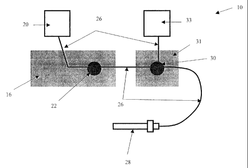
FIG. lA illustrates one exemplary embodiment of a high pressure fluid jet
system 10 that is useful to cut hard materials in a surgical procedure by
combining
particles of an abrasive material with a stream of pressurized fluid. As
shown, the
system 10 can include a fluid source 20, such as a saline, that is in fluid
communication
with a drive mechanism 16. The drive mechanism 16 communicates the fluid to a
suspension pump drive mechanism 31 such that a concentrated suspension of
abrasive
particles and delivery liquid, such as saline, (the "slurry") 33 can be
combined with a
pressurized stream of fluid prior to the pressurized stream of fluid entering
a fluid jet
delivery device or an application tool 28. The fluid source 20 can be coupled
to the
drive mechanism 16 using a variety of techniques, but in one exemplary
embodiment the
fluid source 20 includes a conduit 26 (discussed in more detail below) that
extends
between the fluid source 20 and the drive mechanism 16. Likewise, the drive
mechanism 16, the suspension pump drive mechanism 31, and the application tool
28
CA 02529260 2005-12-06
_7_
can also be connected by a conduit 26 extending therebetween. A person skilled
in the
art will appreciate that the high pressure fluid jet system can include a
variety of other
components, and that each component can have a variety of configurations.
Moreover,
the components can be integrally formed with one another or they can be
removably
attached to one another.
While virtually any known drive mechanism 16 can be used, the drive
mechanism I6 can include a pump console 22 for pumping fluid from the fluid
source
20 through a pump cartridge (not shown) at a controlled rate. The exemplary
pump
console 22 can include a push rod that is driven by a motor disposed within
the pump
console 22, and that includes controls to allow a user to input the desired
pump
parameters. In use, the motor is effective to reciprocate the push rod along
its axis,
thereby reciprocating a piston disposed within the pump cartridge to pump
fluid through
the cartridge towards the application tool 28.
Connected to drive mechanism 16 (by conduit 26) is a suspension pump drive
mechanism 31 which delivers a concentration of slurry 33 into the pressurized
stream of
fluid. The slurry can include any combination of the abrasive materials
disclosed herein
mixed or suspended within a delivery liquid, e.g., saline. However, by way of
non-
limiting example, the slurry contains at least about 40% of abrasive solid
particles by
volume, and in a preferred embodiment at least about 20% of abrasive solid
particles by
volume. The suspension pump drive mechanism 31 is similar to the drive
mechanism 16
and, as shown in FIG. 1B, has a slurry pump console 30 which can include a
piston 40
which slidably moves within a pump cavity 38 such that the slurry is pushed
into the
pressurized stream of fluid.
The pump cavity 38 of slurry pump console 30 can have a variety of
configurations, however it generally is complementary in shape to the piston
40 and has
an inlet port 32 through which the slurry enters the cavity 38 and an outlet
36 through
which the slurry exits the cavity to ultimately mix with the pressurized
stream of fluid.
The inlet port 32 can be of any size, shape and configuration that renders it
capable of
transporting the slurry. In one embodiment, however, it is a conduit 26
(discussed in
more detail below) reversibly or integrally mated to a valve mechanism 34. A
variety of
valve mechanisms 34 can be used so long as they are capable of controlling the
rate and
amount of slurry which enters into the cavity 38, such as, for example, a
manual valve, a
CA 02529260 2005-12-06
_g_
two-way valve, a one-way valve, or an automatically or electronically
controlled valve.
One skilled in the art will appreciate that the ability to control the amount
of slurry
entering the cavity 38, and ultimately the application tool 28, allows a
surgeon to
S perform a variety of different procedures using a variety of different
abrasive materials.
While the piston 40 can have any known configuration, the piston 40 is
generally
constructed so that it is able to move within the pump cavity 38 such that the
slurry is
dispensed through an outlet 36 towards the application tool. The outlet 36 can
also be of
any configuration known in the art to transport the slurry, however, by way of
non-
limiting example, it is an integrally formed or removably mated conduit 26
(such as is
discussed below). Once the slurry is dispensed through the outlet 36, the
piston 40 can
then retract, thereby allowing slurry to refill the pump cavity 38.
Referring back to FIG. lA, the fluid delivery conduit 26 can also have a
variety
of configurations. In one exemplary embodiment, the fluid delivery conduit 26
can be
formed from a material which has sufficient burst strength to safely deliver
fluid at a
high pressure to the application tool 28. The material should also be flexible
to enable a
surgeon to manipulate the application tool 28 freely. The fluid delivery
conduit 26 can
also include connectors, which in an exemplary embodiment can be hand
tightened, to
connect the ends of the fluid delivery conduit 26 to the fluid source 20,
drive mechanism
16, suspension pump drive mechanism 31, and/or application tool 28, where
detachable
components are desired. As previously indicated, the fluid delivery conduit 26
can be
integrally formed with or removably mated to the fluid source 20, drive
mechanism 16,
suspension pump drive mechanism 31, and/or application tool 28.
The application tool 28 can also have a variety of configurations, and
virtually
any device for forming a high pressure fluid jet can be used with the various
embodiments disclosed herein. For example, the application tool 28 can include
a lumen
in fluid communication with the delivery conduit 26 and a nozzle for forming a
high
pressure fluid jet. The application tool 28 can also include an evacuation
lumen for
collecting and withdrawing fluid, as well as a variety of other features for
facilitating use
of the device. By way of non-limiting example, one exemplary embodiment of a
fluid
jet device is disclosed in commonly owned U.S. Patent Appl. No. 10/904,456
filed on
November 1 l, 2004 and entitled "Methods and Devices for Selective Bulk
Removal and
Precision Sculpting of Tissue" by McRury et al.
CA 02529260 2005-12-06
-9-
FIG. 2 illustrates another embodiment of the present invention in which
abrasive
particles are entrained in a pressurized stream of fluid 114 after the fluid
exits a nozzle
128 of an application tool or fluid jet delivery device. As shown, a second,
collimating
nozzle 131 surrounds the nozzle 128 of the application tool and forms a cavity
129
which maintains the slurry around the nozzle so that when the pressurized
stream of
fluid 114 enters the cavity 129, some of the abrasive particles in the slurry
become
entrained within it, and the abrasive-containing pressurized stream of fluid
exits the
cavity 129 through opening 125.
While the collimating nozzle 131 can have a variety of shapes, in one
embodiment the collimating nozzle 131 has a shape which complements the shape
of the
nozzle 128 of the application tool. The collimating nozzle I31 can also have
an inlet
port 127 which allows for the entry of the slurry into the cavity 129, and in
a preferred
embodiment, the inlet port 127 includes a conduit (not shown) which is
connected to a
large supply of the concentrated slurry.
While the cavity 129 can be a variety of shapes, as shown, the cavity 129 is
complementary to the shape of the collimating nozzle 131. The cavity 129
further can
be a variety of sizes, however it should be large enough to maintain a
presence of slurry
around the nozzle 128 of the application tool. In use, once the cavity 129 is
filled with
slurry, the pressurized stream of fluid 114 flows into the cavity 129 via the
nozzle 128.
The influx of the pressurized stream of fluid 114 into the cavity 129 creates
suction or a
vacuum within the cavity 129, and, as a result, the slurry becomes entrained
with the
pressurized stream of fluid 114. The abrasive-containing pressurized fluid
stream exits
opening 125 in the collimating nozzle 131, and can then be used to cut hard
material
upon contact. One skilled in the art will appreciate that this embodiment
provides the
option of on-demand control to engage and/or disengage the flow of the
abrasive
material.
FIGS. 3-4B illustrate alternative embodiments of the present invention in
which
the pressurized fluid stream can erode a suspension or solid form of the
abrasive
material resulting in the abrasive solid particles becoming entrained within
the
pressurized stream of fluid. Referring first to FIG. 3, the pressurized stream
of fluid 214
flows out of the nozzle 228 of the high pressure jet 212 and contacts a supply
211 which
contains the abrasive material. Once the pressurized stream of fluid contacts
the supply
CA 02529260 2005-12-06
-10-
211, a portion of the abrasive material is eroded, resulting in abrasive
particles becoming
entrained within the pressurized stream of fluid 214 such that hard material
200 can be
cut upon contact.
One skilled in the art will appreciate that the supply 211 of abrasive
material can
be a variety of forms, depending upon the type of material used. In exemplary
embodiments, the supply 211 can be a solid which is rod-shaped (as shown),
cylindrical,
or any other shape, or a suspension. Further, the supply 211 can have any
configuration
which can hold the abrasive material, such as, for example, a conduit. The
supply 21 I
can be directed to the pressurized fluid stream 214 in a variety of ways,
however, in an
exemplary embodiment it is cross-fed into the pressurized fluid stream 214.
One skilled
in the art will further appreciate that this embodiment requires a very short
residence
time of the abrasive before it is delivered to the hard material, so that
abrasive materials
other than those mentioned above, such as crushed ice, may be used.
I 5 FIGS. 4A-4B illustrate an alternative embodiment of the present invention
in
which the pressurized stream of fluid 214 erodes a portion of a cutting
template 257
placed on the hard material 200. The cutting template 257 can be any form
which
allows for hard material to be cut in a desired pattern, however, by way of
non-limiting
example, the template 257 can have a solid region 262 and an open region 260,
as shown
in FIG. 4B. The solid region 262 can be made of any biocompatible material
such as a
metal (e.g., stainless steel) or a polymer (e.g., high density polyethylene or
Polyetherether Ketone (PEEK)), or any other material that will not erode when
contacted
by the pressurized stream of fluid. The solid region 262 can also be a variety
of shapes,
such as a plate or a cartridge, so long as the shape can contain within it an
open region or
cutting region (such as open region 260, for example) having an agglomerate of
abrasive
material. The open region 260 can be formed from any occlusion of the abrasive
materials listed herein and can be a variety of shapes depending upon the type
of cut
desired by the surgeon, such as a line, a plug, a circle, etc., however as
shown the open
region 260 is a crescent shape.
In use, as shown in FIG. 4A, the pressurized stream of fluid 214 flows out of
the
nozzle 228 of the high pressure jet 212 and contacts the template 257. Upon
contact, the
abrasive material in the open region 260 is eroded by the pressurized stream
of fluid
214, resulting in abrasive particles becoming entrained within the pressurized
stream of
CA 02529260 2005-12-06
-11-
fluid 214 while the solid region 262 remains unchanged. As a result, the hard
material
200 is cut in a pattern which complements the pattern of the open region 260.
One
skilled in the art will appreciate that because the solid region 262 does not
erode upon
contact with the pressurized stream of fluid 214, it can be reused.
One skilled in the art will further appreciate further features and advantages
of
the invention based on the above-described embodiments. Accordingly, the
invention is
not to be limited by what has been particularly shown and described, except as
indicated
by the appended claims. All publications and references cited herein are
expressly
incorporated herein by reference in their entirety.
What is claimed is: