Note: Descriptions are shown in the official language in which they were submitted.
CA 02529426 2005-12-14
WO 2005/005883 PCT/CA2004/001006
~ERTZCa~.LY ai~JUST~BL>w DEVICE FQR SLrSpENDING
AN AF.TIC~.E hR.QNi A C~IL.ING
BACKGROU~11~ GF THE INVEN~T'I~N
1. Field of the invention
The present invention relates to ceiling-rnouttted fixtures and, rrmre
particularly> tee a device that can be mounted to a ceiling for suspending an
article, e.g.
a plant, franc the ceiling_
2. I~esGx~tiorf of the Prior Art
It is well knor~.m to secGtre hooks to a roonn's ceiling in order to suspend
from the pools various articl~a, such as planters.
When it is desired to access the planter, for instance for watering
purposes, cane must generally stretch upwardly in order to reach the planter
or must
even step on a chair as planters are generally suspended in a substantially
elevated
position in order not to impede circulation of people in their vicinity.
~'lIe di~culties encountered while trying to reach an article suspended
from a ceiling hook may even be dangerous, for instance when substantially
aged
people use chairs ar other elevatioil means to access the planter.
some devices have been developed to raise and lrawer a suspended
sJ plant, such as the Adjustable plant handing device disclosed in U.S. Patent
No.
a,Ob>,97I > which issued an Nov=ember 19, 1 X91 to Cuaubo- 'a~lm height
adjustable
d~~~ice of this Patent comprises f1 lockrng rrzechanism mounted above the
planter, a
handle and a cable attached at a first end tlaereaf to the planter and at
second and
thereof tc~ a reel biasedly mounted in the handle. The Gable passes through
the locknlg
~a rr~mnber and is partly wound around the handle's reel- llle lockuag
mecltatlzsm
includes a paix of fined wheels which guide the cable therethrough, and a
toothed
locking arm. pivotally tnouiited therein. The,locleing ann is biased towards a
first one
of the e~The~ls, wheret~y the cable can be secured beEween the locking arm and
the f rst
wheel. '1"ensian provided in the cable by the handle drams the laclcing arm
away from
3 t7 the cable so as w release the latter and allow movement thereof through
the locking
ntechanisxxl, whereby the planter can be selectively raised and lowered. '~'he
toothed
loclei.ng arnl returns to a cable lacking position against the first wheel by
providing a
-1-
CA 02529426 2005-12-14
WO 2005/005883 PCT/CA2004/001006
sudden slack in ihc cable via the handle. A disengageable brake acting on tl~e
reel
allows the handy to be positioned~t various elevations.
SLTMMAI~'~' OF Tl-iE INVENTION
It is therefore an aim of the present invention to provide a novel ceiling
1=xxture that allows an article attached thereto to be raised and lowered.
It is also an aim of the present itxventian to provide a oiling ~ixriu~
that allows an article attached Chereto to be raised and lowered and Which can
selecti~'~ly lack the aa-ticle at vaz-iotzs elevations.
Therefore, in accordance with the present invention, there is provided a
vertically adjustable fixture adapted to be secured tU an Averhead surface,
comprising
a base zizember adapted to be secured to a surface, a flexible elongated
member
retractable in and extendable out e~f said base member, a rc~tatable reel
provided in said
~ 5 base member with said elongated member being partly wound around said
reel, and a
locking zn~chanism adapted in a lacked position to lock said elongated member
with
respect to said base member, writh sand elongated member being selectively
displaceable to disengage said lacking mechanism to an unlocl:.ed position
thereby
allowizzg said elongated me:z~r~.ber IU be displaced relative to said base
member by
al G selectively retracting said elongated member into, or withdrawing it
~rorn, said base
member.
More particularly, said locking mechanism is provided in said base
member, said elongated member including a series of spaced apart enlargements
distributed thereon, said locl~ing mecharzisrrz being adapted to engage in
said locked
5 position at last one pf said enlargements thereby preventing said elongated.
nxember
from further unswinding frozn sand reel.
I°ypically, sdzid enlargements include beads that are substantially
equally spaced one ait~r the other. Far instance, said elongated member can
cazYZpz~se
a string extending through said beads, said bEads being fixedly zrzourzted to
said string.
3 a ~ Fuz-therrrzore, said locking member can include a receiving means
adapted to rs:cei~-e therein one ot~ said enlargements, said elongated member
beriveen
said enlargements thereof bc;ing slidable in and out of said receiving means
rWhen said
anc~ of said enlargen~zents is dislodged from said receiving means. Tn sach a
case, said
CA 02529426 2005-12-14
WO 2005/005883 PCT/CA2004/001006
receiving means can c:on~prise an angled retention element that opens up onto
an
opening defined at a loader end caf said base membex and through which said
elongated
menzher extends.
For example, said retention element comprises a recess adapted to
receive said one of said beds, and a notch joitung said opening, and a bottom
of said
recess, said elongated merraber between said enlargernents thereof being
slidable in
and out of said recess via said notch, wherein in said loc[~ed position said
one head is
lodged ~ in said recess with gravity fiarces acting downwardly on said
elongared
member retaining said one bead in sand recess, and wherein, tea disengage said
one
L:.~ bead from said locking menmber, said gravity forces are sufficiently
appc~sed for
allowing, said one bead to be rerriaved from said recess thereby allowing said
elongated member to be wound around, or unwound from, said reel for changing
an
elevation of an article suspended by said elongated member.
:~Ite~~rra.tively, said retention element comprises a pair of spaced apam
fingers defining a gap therebetween which communicates at one end thereof with
said
opening and which is sul~~:iently closed at a.n opposed end thereof, said
elongated
n-~ember between said enlargements thereof being adapted to be received in
said gap
while said one bead is supported by said fingers, wherein in said locked
position said
ore bead is supported by said fingers gravity forces acting downwardly on said
2 C~ elongated member retaining said one bead on said fingers, and wherein, to
disengage
said one bead lionz said locking member, said gravity forces are sufficiently
opposed
for allowing said one bead to be withdrawn from said fingers thereby allowing
said
elongated n tember to be wwntnd around, or unwound fr~an~, said reel far
changing an
elevation of an article suspended by said elongated member. Typically, said
fingers
~ 5 arc: angled dow~nv~ardly in a direction away from Said opening of said
base member.
Moreover, a shafr is fixedly mounted in said base member, said reel
being rotatable about said shaft, a biasing; means being prcwided between aaid
reel and
a tied part of one of said. base member and said shaft, said biasing means
being
adapted to encourage winding of said elongated member around said reel. Said
biasin;~
3 C nn:.ans exerts a spring force less than a downward force exerted on said
reel by an
a3-ticle suspended from said elongated member, whereby in a suspended position
of
xlre article, said Inching m.eehanism retains said one of aaid enlargements in
said
locked position, whereas to disengage said one bead from said locking member,
said
_3_
CA 02529426 2005-12-14
WO 2005/005883 PCT/CA2004/001006
downward forces are suf~ci~ntly opposed to alla~,v said elongated member to
assume
said unlocked position thereby allowing said elongated member to be wound
around,
ar unwourxd~fram, said reel far chaz2~,ing an elevation ofihe article-
Also, a shafx Mange is gezaerally provided an said shaft aurwardly of
said reel, said reel including a hub for receiving windings of said elangW ed
member
tlxerearaund, said hub being ratatably mounted around said shaft, ~rsG and
second reel
flanges being provided at opposed ends of said hub for retaining said windings
around
said hub. Said hub znay be of frusto-conical shape:
A wall may attend betweezr said shaft flange and said first reel flange
7. L~ thereby d~fizun~; a charnbe.r, said biasing means extending in said
chamber between
said reel and said fixed part. Preferably, said biasing means comprises a
coiled spring-
'fypically, an opening is defzned at a Iawer end of said base member,
said elangdted member extending; through said opening, said shaft being off-
center
with respect to said opening for providing a proper orientation tQ said
elongated
5 zxzernber at, and/or adjacent to, said locking member.
Advantageously, a marking is provided on an outside surface of said
lease member for indicating to ~t user at Ieast one direction in which said
elongated
member is to be displaced t.o axzove said locking rnechanisrtz to said
unlocked position.
Furthermoa~e, said shaft may be angled with respect to a vertical plane
2 ~ attending through a portic?n of said elongated member v~~hich extends
outwardly of
said base umber cr d along said direcuarz.
Typically, a connector is provided at an end of said elongated member9
which is located outside of said base member, said coiule~°tor being
adapted for
suspending an itez~rz rberefrc~m.
~5
Also in ac.cordaztce with the present invention, there is provided a
vlerti~:ally adaustable fixture adapted co be seetzrad to an overhead
'surface, comprising
a base member adapted to be secured to a surface, a flexible elongated
rtzexnbEr
retractable in and extez;dabl~ out of said bas-r rnenzber, and a lacking
mechanism
adapted in a locked pasitissn to Iock said elongated meri~ber with respect to
said base
member, with said elongated member being selectively displaceable to disengage
said
locking mechanism to an unloctced position thereby allou~~ing said elongated
member
CA 02529426 2005-12-14
WO 2005/005883 PCT/CA2004/001006
to be displaced rel&tive to said base n~.ember by selectively reuacting said
elongated
member unto, or withdrawing it frorrz, said base member.
Further in accordance with. the present invention, there is provided a
vertically adjustable fixture adapt~:d to be secured to an oV~rhead surface,
comprising
a base member adapted to be >rcured to a surface, and a flexible elongated
member
retractable in and extendabl-r. out of said base member, said k~ase menxber
including a
fixed member adapted to be mounted to the surface, a mobile member and a
locking
member, said locking member being adapted in a locked position thereof to lock
said
~ 0 mobile member to said fzxed rnerxtber and being adapted in an unlocked
position
thereof to allow said mobile to displace relative to said axed member while
causing
said elongated member to selectively retract into, or withdraw from, said
loose
member.
More partieu~ariy, said mobile merrrber ec~mprisos a reel capable of
rc~ta.~tion within said fi~.ed member, said elongated tnember being wound
around said
reel, said locking memher being adapted to engage or disengage said reel and
thus
reslaeetively adopting said Iocke<l or unlc~ck~d position depending on a
position of a
portion of said elongated member extending blow said base member, whereby said
portion of said elongated member may be displaced for selectively tnamng said
? ~J locking merclbcr into, or otat of, engagement ~~ith said reel thereby
respectively
preventing or allawina said elongated member to be vertically displaced
relative to
said. base member.
Typically, said locking member is mounted to Said elongated member within said
base
member, and a spring is provided between said fixed member and said mobile
~ 5 n~emb~r for urging, when in said uriloGked position, said elongated
rrternber towards a
retracted gositiori.
Still further in aecordan~e with the present inverztican, them is provided
a method for ~:hrtt7.~;iax; an elevation of an .item suspended from a fixtuxe,
comprising
0 the steps of:
(aj providing a fixture havin:b a base adapted to be moon fed to an
o~~~rhead surface, a flexible elongated n~~mber retractable in arid extendable
trot of
CA 02529426 2005-12-14
WO 2005/005883 PCT/CA2004/001006
said base, an item attached to said elongated member being in a suspended
attitude
thereofn said elongated menilaer being in a locked position with respect to
said base;
tl~) elevating said item and displacing said elongated member sideways
t0 an LLrklaCked position thereof;
(c~ selectively winding said elongated member around said reel or
urm~inding iz therefrom anti! said item is substantially at a desired
elevation; and
td) handling said elongated member back into said locked position
while releasing said item to aaid suspended attitude thereof.
~G l3RlEF 13ESCRipfI(JN C.?F 'f~IE DI~A~TG~
Having thus generally described the nature of the invention, reference
will now be made to the accompanying drawings, showing by way of illustration
a
preferred embodiment thereof, and in which:
Fig. 1 is a perspective view of a ceiling heal: in accordance with a first
i J embodiment of the present invention shown in a first, rexracted, position;
,
Fig. ? is a perspective view, simihu to Fig. l, but showing the ceiling
Ro~ak in a more extended position;
Fig. 3 is an exploded perspective view off' a ceiling hook in accordance
with a second embodiment of tine present invention;
'2 0 Fig. ~ is a perspective view ref the ceiling hook of Fig. 3 minus an
aesthetic co~~er thereof that is net shown in Fig. 4 for illustration
purposes;
Figs. ~A to SD are respeetively perspective, top plan, franc elevational
and side elevational views ol'a ~aase of the ceiling hook of Figs: 3 and 4; ,
Figs. fA to ~~~ are respectively perspective, top plan, franc elevational
2 ~~ and side elevational views of a reel of the ceiling hook of Figs. 3 and
4;
Figs. 7A. to 7I~ are respectively perspective, top plan, franc elEVational
and side elevational vielvs of a l~aeking mechanism of the ceiling hook of
pigs. 3 and
~1;
Fig. 8 is a perspective view of a ceiling device: in accordance with a
~ third embodianent of the pa-esent invention;
Fig. 9 is an elevational view of the ceiling device of Fig. 8;
Fig. 10 is an enlar; ed view of 'the portion of the oiling device
indicated by bubble I(I-IG in Fig. 8;
CA 02529426 2005-12-14
WO 2005/005883 PCT/CA2004/001006
Figs. l I and 12 are respectively vertical front and side cross-secuorAal
views of tfZe ceiling device of Fig. 8;
Fig. 1 ~ is schematic top plan view of Fig. I 1;
Figs. I~, 15 and 16 are respectively detailed front elevationaln side
~ elevational az~d top plan views of ann a-~lr of the ceiling device of F'ig.
~;
Figs. 1 a, I8 and 19 are respectively detailed front clevational, tap plan
arid rear elevational views off' a reel of the ceiling device of Fig. ~;
Fig. 20 is an enlarged view of the portion of the reel indicated by
bubble 2~-2U in Fig. 19;
::. C Fig. 21 is a vertical cross-sectional view of the reel taken along line
2I -
'~ 1 in Fig. I7;
Figs..22 and ~?3 are respectively front elevational and tap plan vieu-~s of
a caper of the ceiling device of Fig. $;
Figs. 24 and ~5 are crass-sectional views t~.kken respectively along line
2~-2~ and line 2S-?S in l~ig. ?~;
Fibs. 'fib and '?7 are respectively top plan and front elevational views of
a k~ase of the ceiling device of Fig. i39 and
F'ig. ?~ is a cross-sectional view taken along line 28-?8 in Fig. '~~.
~ I~FS~yLI''T'1C)N ~F TILE PI2~FFF~EI:~DIMENT~
In accordance u,~ith the present invention, Figs. 1 and '~ illustrate a
ceiling hook. H' that comprises a base IO' adapted to be secured to a ceiling
C', a hook
1?' for suspending articles therefrom, such as planters, and a retractable
cable 14', or
the like, that connects the hook 1?" to the base 1 Q'. Generally, a lower end
of the cable
'~ 5 I4' is Iixeclly attached to am upper end of the hook I?', whereas do
upper end of the
Gable I4' is secured to a mechanism located inside the base 10' and adapted to
allow
the cable 1=k' ~o retrace in, car to be extended from, the lease IO'> thereby
adjusting the
elevation of the hook 1'~' aizd th Lis Of the az~icle attached thereto. The
base IQ' defines
an elongated, e.g. oblong, opening I6' in a Lower wall 1S' thereof, with the
cable 14'
extending downwardly tlwough the base 1Q' via the elongated opening 1b'. The
iz~terrzal st;~ucnu~e of the base IQ' will become nacre apparent from the
fc~llawing
de~~:rilation of a variant ceiling hook H illustrated in Figs. 3 to 7.
_7_
CA 02529426 2005-12-14
WO 2005/005883 PCT/CA2004/001006
Accordingly, Figs., 3 to 7 illustrate the oiling hook H wIuch is
substantially sin-tilar to the ceiling hoop H' of Figs. 1 and ~, e~.eept for
the shape of
their respective hooks and of the; external covers of their bases. More
particularly, the
ceiling hook H comprises a base 10, a hook I?, a calale 14, and an elongated
opening
I 6 defined in a lower wall 1 S pf a cover 2Q of the base 10.
The hook ]? cazi obviously take various configurations, such as the
dosed hook I2 of Figs. 3 and 4> the open hook 12' of Figs. I and 2, etc.
T he base 1~0 c:oniprises an annular member ?2 adapted to be fixedly
secured to the ceiling, the annular member 2'~ being shown in isolation in
Figs. 5A to
S~. The annular n~zamber 22 comprises, a substantially atu~tular exterior
housing ~4, an
26 a'~tending radially inwardly from the housing 24 and a hula Z~ extending
downwardly from an inner end of the arm 26 and centrally of the housing ?4.
The hub
?$ defines at a lower end tl-~eres~f a circular groove 30 adapted for
receiving a carclip
3'? far masons which will become apparent hereina~er. The annular member '??
includes a toll spring 3~.
The base 1C~ also includes a reel 36 which defines a central opening 38
such that the real 36 can be rot4-~tably engaged around the hub ?8 and
retained thereat
with the circlip 3?. The reel 36 is thus rotatably mounted to the hub ?8 and
thus within
the axznular member 22. 'The reel 36 is shown in isolation in Figs. 5A to 6D~.
The reel
36 defines an upper circular channel ~0 and a lower annular array of ratchet
teeth 4~_
A.s seen an Figs. 3 -and 4 and in isolation in higs. 7A to 7D, a toothed
lacking member 4~ comprises a cenual cylinder 46, a radially extending arm 48
Provided. at its upper end with a locking element 50 defining a series of
ratchet teeth
S2, and a pin » extending horizontally sideways of the radial arrn ~-~.
°1 he calale I4
'~ 5 o.~mnds tluottgh the cylinder 46 of the locking rrzetnber ~4. The locking
member 4~-
typically rests onto the internal surface of the cover ?0 with its cylinder 46
having a
lom~er end thereof engaged in the oblong opening lb. When at rest, the
cylinder 46 azid
tlx4 cable I~ eatcnd veI-tically through the cover ?fl, that is on arz inside
end of the
oblong opening 1~, with the cylinder ~6 and the cable I~ being generally co-
linear
3 0 with an a.~ is of the hub ~' ~ and a rotation axis of the reel 36.
The coil spring 34 is typically fixedly connected at opposed ends
thereof to the housing 24 of the annular rrzerrzher ?~ and to the reel 35. The
cable I~
'xtcnds upwardly from the hoof 1? thxough the oblong apen.lng 16 and cylinder
46,
_g_
CA 02529426 2005-12-14
WO 2005/005883 PCT/CA2004/001006
through a central aperture a~ defined in the hub 28, sideways arid outwardly
along the
radial arm ?6, downwardly along the housing 24 and is then inwardly secured to
the
reel ~6, such that rotation of the reel 36 causes the cable l~ to wind on, or
to unwind
from, the channel ~0 of the ree! a6. Rotation of the reel 36 is prevented by
the
engagement of the Meth S? of the lacking element 50 of the locking trrerxrber
4~ with
the teeth 4? ofthe real 3b.
~ecordingly, when it is desired to lower the hook I2, from which far
example there is suspended a plaxater, il~e planter is displaced sideways by
the user,
that 1S r~lgll~ the direction of-the rablong openin; 16 and towards an outer
end thereof,
G sueh a tnovernent of the planter and of the cable 1~- causing the
displacement of the
cylinclar 46 outwardly within the oblong opening 16, thereby disengaging the
locking
xnem6er 44 frorr~ the teeth 42 of the reel 36. 'Then, as the noel 3~ is able
to rotate
within the annular mearber ~'?, the user can allow the plant~:r to displace
downwardly
by gravity, while the user supports the planter in its descent, until the
planter is at a
1.5 desired height, at which point tlai: user brings the planter centrally
under the ceiling
pool'. H such that the cylinder ~5 displaces inwardly along the oblong opening
t 6 and
causes the locking olerrlent SO cormected thereto to engage the teeth 4? of
the reel 35
thereby locking the reel ~6 and thus retaining the hoof' 1? at the selected
height.
It is noted that, when the teeth 42 and S2 are disengaged from each
2 0 other arid during the Lowering of the hook 12, thr cable 14 unwinds from
the reel 36
aba.inst the bias a~f the coil spring 34, with the cable 14, as it unwinds,
displacing
iam~'ardly along the arm Vita, downwardly ilr-ough the aperture Sf> of the hub
2~,
Cluough the cylinder 46 of the looking member =t4 and through the oblong
opening 1 ~.
When it is desired to raise the hoop 12 and the article attached thereto,
5 tl'~° hook 1'~, t~Tpically by way of sand article, is simply raised,
and assistance is
provided by the biased coil spring 34 which causes the reel 36 to rotate
thereby
gradually winding the cable 14 c~ithin the channel ~0~ of the reel 36. Such a
rotation of
the reel "a6 is not prevented by the locking member ~~ in view of the ratohet-
rypc
ci~n~guratic~n of the teeth ~~ and 52 respecuvely of the reel 3b and of the
locking
O element ~0 of the toothed looping member 44.
It is noted that the cover 20 is not show~tt in Fig. 4 for illustration
purposes.
_g_
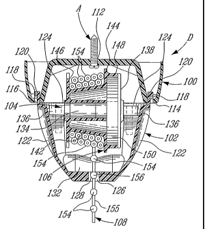
CA 02529426 2005-12-14
WO 2005/005883 PCT/CA2004/001006
Figs. 8 to 28 illustrate a vex2ieally adjustable device D also in
accordance with the present invexztion, for suspending, an article, e.g. a
plant, lrozrz a
ceiling. The device I~ comprises basically a base 100 {see also Figs. ?6 to
?~) adapted
to be secured eo the czilirzg, a cover 102 (see also Figs. ?? to ?>} adapted
to be
rrtounted to the base 100, an extensiozl/retraction mechanism including an
axle 104
(ace Figs. 14 to 16) and a r~:el I06 (see Figs. I? to "? 1 } both contained in
the cover 102,
a strong beaded cable 3 08 parth~ wound around the reel 106 (as best seen an
Fig. I2}
and extending through a lo~xrer end of the cover I02, and a connector such as
a hoofs
11 ~ that is provided on the cable 108 outwardly of the base 100 and of the
cover (and
'' 0 typically at a lower end of the cable I08) and to which the article (not
shown) to
suspend f~onz the ceiling is attached. The base 100 and the cover 10? form a
base
member.
The base I ()0 is txzounied to the ceiling via an appropriate anchor ~
(see Fi,~. 12) extending upwardly through opening 112 defined in the base 100
and
into the ceiling. A lower dawnwardly extending ring 11~ of the base I00
dal:znes four
Slots 11 ~i at~.d four associated locking tabs 11 ~_
The cover 102 includes at an upper end thereof four upwardly
e:aendizx.g L-shaped locking talas 120 adapted to be slid through tkze slots I
16 of the
base 100, such that subsequent rotation of the cover I02 causes the locking
tabs 120
thereof tt~ slid above anti along the locking tads 11 ~ of the base 100 and to
thus
become engaged therehehind, whereby the cover 102 is fzrrnly secured to the
base
100. Basses can he defined ozt upper surfaces of the Socking tabs 118 to
oppose the
loc:kizlg tabs 1?0 from displacing relative thereto in a direction that could
result in the
l°UVe1' 1~~ disetlfafJ'lll~ fTCITT1 tllC base Itl~.
5 The cover 1 U? also defines four decorative indentations I22. On the
onside surfaces of t~.vo diametrically Opposed ones of these recesses 122, LJ-
shaped
clips I2:1 (see Figs. 23 to ?5) are provided with the ends pf the axle 10~#
being fzxedly
eul;aged in these clips 1~'~. The cover 102 also defines a Iower apeniz~g 126
and the
~~Ie 1 t?~ is slightly off-center v~~i.th respect thereto (as bear.- seen izz
Fig. 13}. A
substantially half spherical recess 128 is defined at the bottozxz of the
cover 10? and
adjacent to the operzing 1?6 (see Figs. 23 and ?~), ~rith a notch 130 being
defined at
the interlace of the recess 12~ and the opening I?6. The cover I02 also
Includes
tllereinside a guide 132 (ser Figs. ?3 to ?5} for the beaded cable 10~_
-10-
CA 02529426 2005-12-14
WO 2005/005883 PCT/CA2004/001006
The axle 104 (see Figs. 14 to 16? comprises a shaft 134 having opposed
ends 136 that engage the U-shaped clips 1?4..The axle 104 also includes a
flange 138.
The reel 106 (see Figs. 1? to 21) comprises a central opening 14C1 sra
that the reel 105 can rotate about the axle 104. The reel 1 ~6 also includes a
conical
hub 142 and proximal and distal flanges 144 and 14~5> respectively. A short
cylindrical
wall 148 extends outwardly from flee proximal flange 144 with the flange 138
of the
axle 1 G4 abutting the free et~d of the wall 148 thereby forming a
substantially closed
chamber 150 (see Fig. 12 j The short cylindrical wall 148 defines a slit 152
far
receiving one end of a GOIIed spring (trot show-ta,) that is mounted at its
other end to the
1 C. shaft 134 of the axle 1G4. Therefore, when the hook 110 is pulled away
from the cover
J G2> the reel 10~ rotates with the beaded cable 1 GS unwinding therefrom_
Such a
rotation of the reel 106 causes the end of the coiled spring attached to the
wall i4S of
the reel 1 G6 also to -rotate thereby creating a returns fr~r~~ in the coiled
spring (ate its
other end is fixed to the axle 1fl4~.
The beaded cable 1G8 includes a serial of beads 1~4 fixedly mounted
in a regularly distributed n~anzaer onto a suwng cable or suing 1.~5. When an
article is
suspended from the hook 1 J tJ, ~Titla the weight of this article overpowering
the return
spring force, the article is held in a desired elevation by a given bead 156
(amongst the
beads 154) of the beaded cable 108 being securely lodged in the spherical
recess 12$
D (sec Fig. 11)> and with flee string 1~5 nesting in the notch 130. because of
the weight
of the article, rye given bead 1 ~6 canxsot accidentally dislodge from the
spherical
recess 128. The recess I28 could be replaced by other various configurations,
such a>
a pair an parallel fingers (e.g. in the form of a two-pronged fork) between
which the
string 1 ~5 could be slid, but with these fingers Jaeing close enough together
to prevent
'.~ 5 the beads 1 S 4 fi°om passira~, therethrough; the fingers cQUld
be angled downwardly in a
directi~an aw°ay from the ap~ning to force the bead 156 to be raised
(as for the r~eess
1?8) before being disen~;ageable ivrom~tlze fingers.
If it is desired to vertically move the article, it is first manually
slighil.y
elevated so that the rerun's spring force t'aises the given bead 1 ~6 such
that it
3 G disrn~;ages from the spherical recess 128. The article is then moved
sideways away
from the recess I28 (Fig. 1G shows a marking 158 defined on the outside lower
end of
thr cover 102, which indicates in which directions the beaded cable 108 can be
displaced so as to then all«w raising and lowering of th-r article). once the
beaded
_11_
CA 02529426 2005-12-14
WO 2005/005883 PCT/CA2004/001006
cable 108 has been so displaced, it defines an angle relative ts~ the vertical
that allows
the cable i08 to slide through xhe opening 126 in the cover 102, that is
without
interference franc the recess 1?E, the string 155 being located outside ofthe
notch I30.
1'he ;~rticlG can then be raised or lowered and subsequently locked into a
Stew position
by pivoting the beaded cable 108 back towards the vertical and inxo the notch
130 and
by then slowly releasing the article, the weight of which causing a bead (i.e.
the first
bead located above the opening 126 and inside the cover 10'?) to nest in the
spherical
recess 128 and so become tim'tiy engaged therein. The guide I32 ensures that
the
beaded cabfc~ IOf~ coming out cxf the reel lOb is at a proper ;angle relative
to the recess
1?8 and opening 126.
The su3ng/cable 155 of the beaded cable 108 can take the foz-zri of a
string2 a rope, a cable, ecc., and can be made of various legible materials.
The use of
the terravs :able and string h~.-rein is meant to cover such various
apprcapniate elongated
members.
-I?-