Note: Descriptions are shown in the official language in which they were submitted.
CA 02529480 1997-02-27
a
78543-38
APPLICATION FOR PATENT
TITLE: METHOD AND APPARATUS FOR ESTABLISHING BRANCH
WELLS AT A NODE OF A PARENT WELL
INVENTOR(S): HERVE OHMER
BACKGROUND OF THE INVENTION
Field of the Invention
This invention relates generally to the field of
wells, particularly to the field of establishing branch
wells from a parent hydrocarbon well. More particularly the
invention relates to establishing multiple branch wells from
a common depth point, called a node, deep in the well.
Description of the Related Art
Multiple wells have been drilled from a common
location, particularly while drilling from an offshore ,
platform where multiple wells must be drilled to cover the
great expenses of offshore drilling. As illustrated in
Figures 1A and 1B, such wells are drilled through a common
conductor pipe, and each well includes surface casing
liners, intermediate casing and parent casing as is well
known in the field of offshore drilling of hydrocarbon
wells.
Branch wells are also known in the art of well
drilling as illustrated in Figure 2. Branch wells
1
I
CA 02529480 1997-02-27
are created from the parent well, but necessarily the parent well extends
below the branching point
of the primary well. As a result, the branching well is typically of a smaller
diameter than that of the ' .
primary well which extends below the branching point. Furthermore, difficult
sealing problems have
faced the are for establishing communication between the branch well and the
primary well.
For example, U.S. Patent 5,388,648 describes methods relating to well juncttue
sealing with
various sets of embodiments to accomplish such sealing. The disclosure of the
'648 patent proposes
solutions to several serious sealing problems which are encountered when
establishing branches in .
a well. Such sealing problems relate to the requirement of ensuring the
connectivity of the branch
casing liner with the parent casing and to maintaining hydraulic isolation of
the juncture under
differential pressure.
A fundamental problem exists in establishing branch wells at a depth in a
primary well in that
apparatus for establishing such branch wells must be run on parent casing
which must fit within
intermediate casing of the well. Accordingly, any such apparatus for
establishing branch wells must
have an outer diameter which is essentially no greater than that of that the
parent casing.
Furthermore, it is desirable that when branch wells are established, they have
as large a diameter as
possible. Still further. it is desirable that such branch wells be lined with
casing which may be
established and sealed with the branching equipment with conventional casing
hangers.
An important object of this invention is to provide an apparatus and method by
which
multiple branches connect to a primary well at a single depth in the well
where the branch wells are
controlled and sealed with respect to the primary well with conventional liner-
to-casing connections.
Another important object of this invention is to provide a multiple outlet
branching sub
having an outer diameter such that it may be run in a well to a deployment
location via primary
casing.
Another object of this invention is to provide a multiple outlzt branching sub
in which
multiple outlets are fabricated in a retracted state and are expanded while
dow-nhole at a branching
deployment location to produce maximum branch well diameters rounded to
provide conven~.~nal
liner-to-casing connections.
Another object of this invention is to provide apparatus for downhole
expansion of retracted
outlet members in order to direct each outlet into an arcuate path outwardly
from the axis of the
CA 02529480 1997-02-27
r ,
78080-3
primary well and to expand the outlets into an essentially
round shape such that after a branch well is drilled through an
outlet, conventional liner-to-casing connections can be made to
such outlet members.
SDI4~lARY OF THE INVENTION
The invention provides a method of forming a branch
well from a parent well, the method comprising the steps of;
running a branching sub with a parent casing through a parent
well to a branching location, said branching sub including a
branching chamber and multiple branching outlets; and expanding
and forming at least one of said branching outlets until it
achieves a substantially round shape.
The invention further provides a method of forming a
branch well from a parent well, the method comprising the steps
of: running a branching sub with a parent casing through a
parent well to a branching location, said branching sub
including a branching chamber and multiple branching outlets,
at least one of said branching outlets having a non-circular
cross sectional shape; and.circularizing said at least one of
said branching outlets by means of mechanical pressure.
The invention also provides a method of forming.a
branch well from a parent well, the method comprising the steps
of: running a branching sub with a parent casing through a
parent well to a branching location, said branching sub
including a branching chamber and multiple branching outlets;
and expanding and forming at least one of said branching
outlets until it extends in a path beyond the diameter of said
branching chamber.
The invention also provides a method of casing a
well, the method comprising the steps of: deforming to a non-
circular cross sectional shape at least one outlet member of a
branching sub having a plurality of outlet members; attaching
said branching sub to a casing string; positioning said casing
3
CA 02529480 1997-02-27
78080-3
string and branching sub in the well; and expanding and
reforming said least one deformed outlet member to a
substantially circular cross sectional shape.
The invention also provides a method of expanding and
forming downhole at least one outlet member of a branching sub.
comprising a plurality of outlet members, the method comprising
the steps of: positioning a forming tool in said branching
sub, said forming tool having at least one forming head;,
S
positioning said at least one forming head in said at least one
outlet member; and actuating said at least one forming head to
expand and form said at least one outlet member.
From another aspect the invention provides a multiple
branching sub designed and arranged for deployment in a
borehole comprising: a branching chamber having an open first
end of cylindrical shape and a second end, said branching
chamber designed and arranged for sealed connection at said
first end to casing in a borehole; and multiple branching
outlet members, each of which is integrally connected to said
second end of said branching chamber, each of said multiple
branching outlet members being in fluid communication with said
branching chamber, said sub characterized by: a retracted
position for insertion into a borehole in which each of said
multiple outlet members is substantially totally within an
imaginary cylinder which is coaxial with and of substantially
the same radius as said first end of said branching chamber;
and an expanded position in which at least one of said multiple
outlet members extends from said branching chamber in a path
outwardly of said imaginary cylinder.
The invention further provides apparatus arranged and
designed for expanding an outlet of a multiple branching sub in
a cased borehole, where said sub includes a branching chamber
having a first end, a second end, and multiple branching outlet
members each of which is connected to said second end of said
3a
CA 02529480 1997-02-27
78543-38D
branching chamber, with said branching outlet members being
in a retracted condition in which each of said outlet members
is substantially totally within an imaginary cylinder which
is coaxial with and substantially the same radius as said
first end of said branching chamber, said apparatus
including: an uphole power and control unit; a downhole
operational unit; and an electrical wireline means connected
between said uphole power and control unit and said downhole
operational unit for providing a path for electrical power
and electrical communication signals therebetween; said
downhole operational unit including a forming mechanism
arranged and designed for insertion in a retracted branching
outlet member of said sub for expanding at least one of said
multiple outlet members so that it extends in a path from
said branching chamber outwardly of said imaginary cylinder.
In accordance with another aspect of the present
invention, there is provided a method of forming a branch
well from a parent well comprising: running a branching sub
having a branching chamber and multiple branching outlets
with a parent casing through a parent well to a branching
locatipn; orienting said branching sub until its multiple
branching outlets are disposed in a predetermined
orientation; and expanding and forming at least one of said
branching outlets until it extends in a path beyond the
diameter of said branching chamber and achieves a
substantially round shape.
In accordance with another aspect of the present
invention, there is provided a method of forming a b ranch
well from a parent well, the method comprising the steps of:
running a branching sub with a parent casing through a parent
' well to a branching location, said branching sub including a
branching chamber and multiple branching outlets; and
3b
CA 02529480 1997-02-27
78543-38D
expanding and forming at least one of said branching outlets
until it achieves a substantially round shape. ,
In accordance with another aspect of the present
invention, there is provided a method of forming a branch
well from a parent well, the method comprising the steps of:
running a branching sub with a parent casing through a parent
well to a branching location, said branching sub including a
branching chamber and multiple branching outlets, at least
one of said branching outlets having a non-circular cross
sectional shape; and circularizing said at least one of said
branching outlets by means of mechanical pressure.
In accordance with another aspect of the present
invention, there is provided a method of forming a branch
well from a parent well, the method comprising the steps of:
running a branching sub with a parent casing through a parent
well to a branching location, said branching sub including a
branching chamber and multiple branching outlets; and
expanding and forming at least one of said branching outlets
until it extends in a path beyond the diameter of said
branching chamber.
In accordance with another aspect of the present
invention, there is provided a method of casing a well, the
method comprising the steps of: deforming to a non-circular
cross sectional shape at least one outlet member of a
branching sub having ~ plurality of outlet members; attaching
said branching sub to a casing string; positioning said
casing string and branching sub in the well; and expanding
and reforming said at least one deformed outlet member to a
substantially circular cross sectional shape.
In accordance with another aspect of the present
invention, there is provided a method of expanding and
3c
CA 02529480 1997-02-27
78543-38D
forming downhole at least one outlet member of a branching
sub comprising a plurality of outlet members, the method
comprising the steps of: positioning a forming tool in said
branching sub, said forming tool having at least one forming
head; positioning said at least one forming head in said at
least one outlet member; and actuating said at least one
forming head to expand and form said at least~bne outlet
member.
In establishing multiple branch wells from a parent
well, a multiple branching sub is provided for deployment in
a borehole by means of a parent casing through a parent well.
The branching sub includes a branching chamber which has,an
open first end of cylindrical shape. The branching chamber
has a second end to which branching outlet members are
connected. The first end is connected to the parent well
casing in a conventional manner, such as by threading, for
deployment to a branching location in the parent well.
Multiple branching outlet members, each of which is
integrally connected to the second end of the branching
chamber, provide fluid communication with the branching
chamber. Each of the outlet members is prefabricated such
that such members are in a retracted position for insertion
of the sub into and down through the parent well to a
deployment location deep in the well. Each of the multiple
outlets is substantially totally within an imaginary cylinder
which is coaxial with and of substantially the same radius as
the first end-of the branching chamber. The prefabrication
of the outlet members causes each outlet member to be
transformed in cross-sectional shape from a round or circular
shape to an oblong or other suitable shape such that its
outer profile fits within the imaginary cylinder. The outer
profile of each outlet member cooperates with the outer
profiles of other outlet members to substantially f ill the
3d
CA 02529480 1997-02-27
78543-38D
area of a cross-section of the imaginary cylinder. As a
result, a substantially greater cross-sectional area of the
multiple outlet members is achieved within a cross-section of
the imaginary cylinder as compared with a corresponding
number of tubular multiple outlet members of circular cross-
section.
The multiple outlet members a,re constructed of a
material which may be plastically deformed by.cold forming.
A forming tool is used, after the multiple branching sub is
deployed in the parent well, to expand at least one of the
multiple branching outlet members outwardly from the
connection to the branching chamber. Preferably all of the
outlet members are expanded simultaneously. Simultaneously
with the outward expansion, the multiple outlets are expanded
into a substantially
3e '
CA 02529480 1997-02-27
~ i
circular radial cross-sectional shape along their axial extent.
After the multiple outlet members which branch from the branching chamber are
expanded,
each of the multiple branching outlets are plugged. Next, a borehole is
drilled through a selected one
of the multiple branching outlets. A substantially round liner is provided
through the selected
branching outlet and into the branch well. The liner of circular cross-section
is sealed to the selected
branching outlet circular cmss-section by means of a conventional casing
hanger. A borehole and
liner is established for a plurality of the multiple branching outlets. A
downhole manifold is installed
in the branching chamber. Next multiple branch wells are completed. T'he
production of each
branch well to the parent well is controlled with the manifold.
The apparatus for expanding an outlet of the multiple branching sub includes
an uphole
power and control unit and a downhole operational unit. An electrical wireline
connects the uphole
power and control unit and the downhole operational unit. The wireline
provides a physical
connection for lowering the downhoie operational unit to the branching sub and
provides an
electrical path for transmission of power and bidirectional control and status
signals.
The dowttltole operational unit includes a forming mechanism arranged and
designed for
insertion in at least one retracted branching outlet member of the sub (and
preferably into all of the
outlet members at the same time) and for expanding the outlet member outwardly
from its imaginay
cylinder at deployment. Preferably each outlet member is expanded outwardly
and expanded to a
circular radial cross-section simultaneously. The downhole operational unit
includes latching and
orientation mechanisms which cooperate with corresponding mechanisms of the
sub. Such
cooperating mechanisms allow the forming mechanism to be radially oriented
within the multiple
branching sub so that it is aligned with a selected outlet of the sub and
preferably with all of the
outlets of the sub. The dowr~hole operational unit includes a hydraulic pump
and a head having
hydraulic tluid lines connected to the hydraulic pump. The forming mechanism
includes a
hydraulically powered forming pad. A telescopic link between each forming pad
and head provides
pressurized hydraulic fluid to the forming pads as they move downwardly while
expanding the
outlet members.
BRIEF DESCRIPTION OF THE DRAWINGS
The objects, advantages and features of the invention will become more
apparent by reference
CA 02529480 1997-02-27
t
to the drawings which are appended hereto and wherein an illustrative
embodiment of the invention
is shown, of which:
Figures 1 A and 1 B illustrate a prior art triple liner packed in a conductor
casing termination
in which the outlet members are round during installation and are packed to
fit within the conductor
casing;
Figure 2 illustrates a prior art parent or vertical well and lateral branch
wells which extend
therefrom;
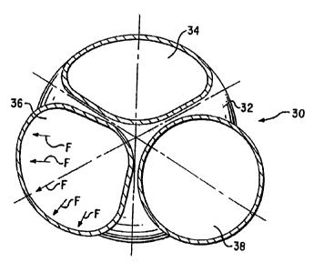
Figures 3A, 3B, and 3C illustrate a three outlet branching sub according to
the present
invention where Figure 3A is a radial cross-section through the branching
outlets of the sub, with
one outlet completely in a retracted position, with another outlet in a
position between its retracted
position and its fully expanded position, and the third outlet being in a
fully expanded position, and
where Figure 3B is a radial cross-section througf: the branching outlets of
the sub with each of the
outlets fully expanded after deployment in a parent well, and Figure . C is an
axial cross-section of
the branching sub showing two of the branching outlets fully expanded to a
round shape in which
casing has been run into a branch well and sealed with respect to the
branching outlets by means of
conventional liner hanging packers.
Figure 4 is a perspective view of a three symmetrical outlet branching sub of
the present
invention with the outlet branches expanded.
Figures 5A, ~B, jC, and SD illustrate configurations of the present invention
with
asymmetrical branching outlets with at least one outlet having larger internal
dimensions than the
other two; with Figure ~A being a radial cross-section through the branching
outlets along line jA-
~A in a retracted position, with Figure jB being an axial cross-section
through the lines ~B-SB of
Figure 5A, with Figure jC being a radial cross-section along lines sC-jC of
Figure jD with the
branching outlets in an expanded position, and with Figure ~D being an axial
cross-section along
lines SD-~D of Figure ~C with the branching outlets in an expanded position;
Figures 6A-6E illustrate radial cross-sections of several examples of
branching outlet
configurations of the branching sub according to the im~ention. with all
outlet branches fully
expanded from their retracted state during deployment in a parent well. with
Figure 6A illustrating
two equal diameter outlet branches. Figure 6B illustrating three equal
diameter outlet branches.
_j_
CA 02529480 1997-02-27
Figwe 6C, like Figure SC. illustrating three outlet branches with one branch
characterized by a larger
diameter than the other two, with Figwe 6D illustrating four equal diameter
outlet branches, and with
Figwe 6E illustrating five outlet branches with the center branch being of
smaller diameter than the
other four:
Figures 7A-7E illustrate stages of expanding the outlet members of an
expandable branching
sub according to the invention, with Figure 7A illustrating an axial cross-
section of the sub showing
multiple branching outlets with one such outlet in a retracted position and
the other such outlet being
expanded starting with its connection to the branching head and continuing
expansion downwardly
toward the lower opening of the branching outlets, with Figwe 7B illustrating
a radial cross-section
at axial position B of Figure 7A and assuming that each of three symmetrical
branching outlets are
being expanded simultaneously, and with Figwes 7C through 7E showing various
stages of
expansion as a function of axial distance along the branching outlets:
Figures~BA and 8B illustrate respectively in arial cross-section and a radial
cross-section
along lines 8B-8B, latching' and orientation profiles of a branching chamber
of the branching sub,
and Figure 8A further illustrates an extension leg and supporting shoe for
deployment in a parent
well and for providing stability to the branching sub while expanding the
branching outlets from
their reuacted position;
Figure 9 schematically illustrates uphole and douwhole apparatus for expanding
the
branching outlets of the branching sub;
Figure 10 illustrates steps of the process of expanding and forming the
branching outlets with
a pressure forming pad of the apparatus of Figwe 9;
Figures 11 A-1 1 H illustrate steps of an installation sequence for a nodal
branching sub and
for creating branch wells from a parent well according to the invention:
Figure t ~ illustrates a branching sub deployed in a parent well,and further
illustrates branch
well liners hung from branching outlets and still further illustrates
production apparatus deployed
in the branching sub for controliine production from branch wells into the
parent well;
Figures 1~.~ and ~1~B geometrically illustrate the increase in branch well
size achievable for
this im~ention as compared pith prior art conaentional axial branch wells from
liners packed at the
end of parent casing:
-6-
CA 02529480 1997-02-27
Figures 14A-14D are illustrative sketches of nodal branching according to the
invention
where Figure 14A illustrates establishing a node in a parent well and
establishing branch wells at a
common depth point in the parent well, all of which communicate with a parent
well at the node of
the parent well; with Figure 14B illustrating an expanded branching sub which
has had its branching
outlets expanded beyond the diameter of the parent casing and formed to be
substantially round; with
Figure 14C illustrating using a primary node and secondary nodes to produce
hydrocarbons from a
single strata; and with Figure 14D illustrating using an expanded
brattching'sub from a primary node
to reach multiple subterranean targets;
Figure I SA illustrates a two outlet version of a branching sub according to
the invention, with
Figures 15B, 15B'. 15C, and 1 ~D illustrating cross-sectional profiles of such
v~-o outlet version of
a branching sub with an alternative post-forming tool at various depth
locations in the outlet
members;
Figure 16 illustrates a two arm alternative version of a post-formin; tool:
and
Figures 17A-17D illustrate the operation of such alternative post-forming
tool.
DESCRIPTION OF THE PREFERRED EMBODIMENTS
As described above, Figures IA and 1B illustrate the problems W th prior art
apparatus and
methods for establishing branch wells from a parent well. Figures 1 A and 1 B
show radial and axial
cross-sections of multiple outlet liners 12 hung and sealed from a large
diameter conductor pipe 10.
The outlets are round in order to facilitate use of conventional lining hanger
packers 14 to seal the
outlet liners IZ for communication with the conductor pipe 10. The arrangement
of Figures 1 A and
1 B requires that multiple round outlets of diameter Do fit within the
diameter Dsl of the conductor
pipe 10. In many cases, especially where the conductor pipe must be deploaed
at a depth in the mell.
rather than at the surface of the well, it is not feasible to provide a
borehole of suft7ciern <cuter
diameter to allow branch well outlets of sufficient diameter to be installed.
The technique of providing branch wells according to the prior art arrangement
depicted ir,
Figure 2 creates branch wells 22, 24 from a primary well ?0. Special sealing
arrangements .6. unlike
conventional casing hangers, must be provided to seal a lined branch well
3'_'. 24 to the priman- well
?0.
_7_
CA 02529480 1997-02-27
I?escriotion of BranchinE Sub According to the Invention
Figures 3A. 3B, and 3C illustrate a branching sub 30 according to the
invention. The
branching sub includes a branching chamber 3" (which may be connected to and
carried by parent
well casing (See parent casing 604 of Figure 1?)). and multiple outlet
members, for example three
outlet members 34, 36, 38 illustrated in Figures 3A, 3B, and 3C. Figure 3A is
a radial cross-section
view through the branching chamber 32 which illustrates one outlet member 34
in a retracted state,
t
a second outlet member 36 in the state of being expanded outwardly, and a
third outlet member 38
which has been fully expanded outwardly. ~. (Figure 3A is presented for
illustrative purposes, because
according to the invention it is preferred to expand and circularize each of
the outlets
simultaneously.) In the retracted state, each outlet is deformed'as shown
particularly for outlet
member . =I. a round tube is deformed such that its cross-sectional interior
area remains essentially
the samz as that of a circular or round tube. hut its exterior shape is such
that it fits cooperatively
with the deformed shape of the other outlet members, all within an imaginary
cylinder having a
diameter essentially the same as that of the branching chamber 32. In that way
the branching
chamber 32 and its retracted outlet members have an effective outer diameter
which allows it to be
nut in a parent well to a deployment location while attached to a parent
casing. Outlet member 34
in its retracted state is illustrated in an oblong shape, but other retracted
shapes may also prove to
have advantageous characteristics. For example. a concave central area of
deformation in the outer
side of a retracted outlet member may be advantageous to provide a stitTer
outlet member. Such .
deformation is progressively greater and deeper starting from the top to the
bottom of the outlet
member.
Figure 3.~ shows outlet member ,6 in a state of being expanded in an arcuate
path outwardly
from thz hranchin'_ chamher 32 while simultaneously bzin~_ , roundzd by a
downholz
forming-expanding tool that is described below. The arrows labeled F represent
forces being applied
from the interior of the outlet member 36 in order to expand that outlet
memb~== both outw-at::,: in
an arcuate path asi~ay from branching chamber 3'_ and to circularize it from
its retracted state (as is
the condition of outlet member 34) to its expanded or fully deployed state
like outlet member s8.
Figure 3B is a radial cross-section as vievred by lines B-B of Figure 3C
through the branching
_g_
CA 02529480 1997-02-27
v
sub 30 at the level of outlet members 36. 38. Figure 3C illustrates
conventional casing liners 42,
44 which have been installed through branching chamber 32 and into respective
outlet members 36,
38. Conventional liner hanging packers 46. 48 seal casing liners 42, 44 to
outlet members 36, 38.
As illustrated in Figwes 3B and 3C, if the diameter Ds2 of the branching
chamber 32 is the same as
the diameter Ds 1 of the conductor pipe of prior art Figure 1 B, then the
outset diameter Dc of Figure
3C is 1.35 times as great as the outer diameter Do of Figure 1 B. The liner
cross-sectional area Sc of
the sub of Figure 3C is 1.82 times as great as the liner cross-sectional area
So of Figure 1 A. When
fully expanded, the effective diameter of the expanded outlet members 34, 36,
38 exceeds that of the
branching chamber 32.
Figure =1 is a perspective view of the branching sub 30 of Figwes 3A, 3B. 3C
where the
branching sub is shown after expansion. Threads 31 are provided at the top end
of branching
chamber 32. Threads 31 enable branching sub 30 to be connected to a parent
casing for deployment
at a subterranean location. Outlzt members . -t. ~ 6. 3 8 are shown expanded
as they would look
downhole at the end of a parent well.
Figures ~A-SD illustrate an alternative three outlet branching sub 301
according to the
invention. Figwes SA and ~B illustrate in radial and axial cross-section views
the sub 301 in its
retracted position. Outlet members 34i, 361 and 381 are illustrated with
outlet member 361 being
about equal to the combined radial cross-sectional area of outlet members 341
and 381 combined.
Each of the outlet members are deformed inwardly from a round tubular shape to
the shapes as
illustrated in Figwe SA whereby the combined deformed areas of outlet members
341, 361 and 381
substantially fill the circular area of branching chamber 321. Other
defotmatioit shapes mar be
advantageous as mentioned above. Each deformed shape of outlet members 341.
361 and 381 of
Figwe ~A is characterized by (for example, of the outlet member 341 ) a
circular outer section .-12
and one or more connecting. non-circular sections 343, 34~. Such non-circular
sections 343. ~~~
are cooperatively shaped m-ith section 362 of outlet member 361 and 382 of
outlet member 381 so
as to maximize the internal radial crass-sectional areas of cutlet members
X41. 361 and 381.
Figures sC and ~D illustrate the branchin_ sub 301 of Figures j,~ and ~B after
its outlet
members have been fully expanded after deployment in a parent well. Outset
members 361 and 381
are illustrated as having been simultaneously expanded in a gently curving
path outvs~ardly from the
-9-
CA 02529480 1997-02-27
axis of branching chamber 321 and expanded radially to form circular tubular
shapes from the
deformed retracted state of Figures SA and ~B.
Figwes 6A-6E show in schematic form the size of expanded outlet members as
compared .
to that of the branching chamber. Figure 6A shows two outlet members 241, 242
which have been
expanded from a deformed retracted state. The diameters of outlet members 241
and 242 are .
substantially greater in an expanded state as compared to their circular
diameters if they could not
be expanded. Figure 6B repeats the case of Figure 3B. Figure 6C repeats the
uneven triple outlet
configuration as shown in Figures SA-SD. Figure 6D illustrates four expandable
outlet members
from a branching chamber 422. Each of the outlet members 441, 442, 443, 445
are of the same
diameter. Figure 6E illustrates five outlet members, where outlet member ~4p
is smaller than the
other four outlet members 541, 542, X43, 544. Outlet member X45 may or may not
be deformed in
the retracted state of the branching sub.
Desc~~piion of Method for Expanding a deformed Retracted Outlet Member
Figures 7A-7E illustrate downhole forming heads I22. 124, 126 operating at
various depths
in outlet members 38, 34, 36. As shown on the right hand side of Figure 7A, a
generalized forming
head 122 is shown as it enters a deformed retracted outlet member, for example
outlet member 38.
at location B. Each of the forming heads I 22. 124, 126 has not yet reached an
outlet member. but
the heads have already begun to expand the outlet wall of branching chamber 32
outwardly as
illustrated in Figure 7B. The forming heads 122, i24, 126 continue to expand
the outlet members
outwardly as shown at location C. Figure 7C shows the forming heads l 22, 124,
126 expanding the
outlet members outwardly while simultaneously circularizing them. Forming pads
123, 125. 127
are forced outwardly by a piston in each of the forming heads 12'_', 1 ?4.
126. The forming heads
simultaneously bear against central wall region 1 ~0 which acts as a reaction
body so as to
simultaneously expand and form the outlet members 38. 34, 36 while balancing
reactive forces while
expanding. Figures 7D and 7E illustrate the forming gyp locations D and E of
Figure 7A.
Figures 8A and 8B illustrate an axially extending slot 160 in the branching
chamber 3'_' of
branching sub 30. Such slot 160 cooperates with an orienting and latching sub
of a downhole
forming tool for radial positioning of such orienting and latching sub for
forming and expanding the
-10-
CA 02529480 1997-02-27
multiple outlet members downhole. A notch I62 in branching chamber 32 is used
to latch the
downhole forming tool at a predetetTrtined axial position.
An extension leg 170 projects downwardly from the central wall region 150 of
branching
sub 30. A foot 172 is carried at the end of extension leg 170. In operation.
foot 172 is lowered to
the bottom of the borehole at the deployment Location. It provides support to
branching sub 30
during forming tool expanding and other operations.
a) Descriuti~an of Embodiment of FiEut~9~
Figures 9 and 10 illustrate the forming tool used to expand multiple outlet
members, for
example outlet members 34, 36. 38 of Figures 3A, 3B. and 3C and Figures 7B,
7C, 7D and 7E. The
forming toot includes uphole apparatus 100 and downhole apparatus '_'00. The
uphole apparatus 100
includes a conventional computer 102 programmed to control telemetw and power
supply unit 10.t
and to receive commands from and display information to a human operator. :art
uphoie winch unit
106 has an electrical wireline 110 spooled thereon for lowering dow~tttole
apparatus 200 through a
parent well casing and into the branching chamber 32 of a branching sub 30
which is connected to
and carried at the end of the parent casing.
The downhole apparatus 200 includes a conventional cable head ?02 which
provides a
strength/electrical connection to wireline 110. A telemetry, power supplies
and controls module 204
includes conventional telemetry. power supply and control circuits which
function to communicate
with uphole computer 102 via w7reline 110 and to provide power and control
signals to downhole
modules. Hydraulic power unit 206 includes a conventional electrically powered
hydraulic pump
for producing dowitltole pressurized hydraulic tluid. An orienting and
latching sub 208 includes a
latching device '_' 10 (schematically illustrated) for fitting. within notch
16' of branching chamber 3=
of Figure 8A and an orienting device 21'? (schematically illustrated) for
cooperating with slot 160
of branching chamber 32. V~-'hen the dovnhole apparatus ~_00 is lowered into
branching sub 30.
orienting device 212 enters the slot 160 and the downhole apparatus'00 is
further lowered until the
latching device 210 enters and latches within notch 163.
Fixed traveling head ? 13 provides hydraulic fluid communication ben~~een
hydraulic power
-11-
CA 02529480 1997-02-27
unit 206 and. the traveling forming heads 122,124, 126, for example:
Telescopic links I 80 provide
pressurized hydraulic fluid to traveling forming heads 122,124, 126 as the
heads l 22,124, 126 move
downwardly within the multiple outlet members, for example outlet members 34.
36, 38 of Figures.
7B-7E. Monitoring heads 182, 184, 186 are provided to determine the radial
distance moved while
radially forming an outlet member.
Figure 10 ilhtstrates traveling forming heads 126, 124, 122 in different
stages of forming an
outlet member of branching sub 30. Forming head 126 is shown in outlet member
36, which is
illustrated by a heavy line before radial forming in the retracted outlet
member 36. 'The outlet
member is shown in light lines 36', 36". Where the outlet member is depicted
as 36' in an
intermediate stage of forming and as 36" in its final formed stage.
The forming head 124 is shown as it is radially forming retracted outlet
member 34 (in light
line; to an intermediate stage 34'. A final stage is illustrated as
circularized outlet member 34". The
forming head 12.4, like the other nvo fotTning heads 126. 12?. includes a
piston 151 on which
forming pad 125 is mounted. Piston 151 is forced outwardly by hydraulic fluid
applied to opening
hydraulic line 152 and is forced inwardly by hydraulic fluid applied to
closing hydraulic line 154.
A caliper sensor 184 is provided to detemune the amount of radial travel of
piston 151 and fomline
pad 125, for example. Suitable seals are provided between the piston I ~ 1 and
the fonnine head 1?4.
The forming head 122 and forming pad 123 are illustrated in Figure 10 to
indicate that under
certain circumstances the shape of the outlet member 38 may be "over expanded"
to create a slightly
oblong shaped outlet, such that when radial forming force from forming pad 123
and forming head
I'_"_ is removed. the outlet will spring back into a circular shape due to
residual elasticity of the steel
outlet member.
At the level ofthe branching chamber 32. forming heads 1?2, 1?4. 126, balance
each other
against the reaction forces while forcing the walls of the chamber oumardlv.
accordin~tv the
forming heads 122, 124. 126 are operated simultaneously, for example at level
B of Figure 7A. while
forcing the lower end of the wall of the branching chamber 32 outwardly. Vfhen
a forming head I 22
enters an outlet member 38 for example. the pad reaction forces are event
supported by the central
wall region 150 of the branching chamber 32. The telescopic linla 180 may- be
rotated a small
amount so that the forming pads 127, 125, 123 can apply pressure to the right
or left from the normal
_1~_
CA 02529480 1997-02-27
axis and thereby improve the roundness or circularity of the outlet members.
After a forming
sequence is perfonned, for example at Location D in Figure 7A, the pressure is
released from piston
l 51, and the telescopic links 180 lower the forming heads 122, for example,
down by one step. Then
the pressure is raised again for forming the outlet members and so forth.
The composition of the materials of which the branching sub 30 is constructed
is preferably
of an alloy steel with austenitic structtue, such as manganese steel, or
nickel alloys such as "Monel"
and "Inconel" series. Such materials provide substantial plastic deformation
with cold forming
thereby providing strengthening.
b) ~p~ption of Alternative Embodiment of Figures 15A-1~D. 16 and 17A-17D
An alternative post-forming tool is illustrated in Figures ISA, ISB, 15B',
15C, 1~D, 16, and
17A-17D. The post-forming toot 1500 is supported by common downhole components
of Figure
9 including a cable head '_'02, telemetw, power supplies and controls module
204, hydraulic powe-
unit 306 and ats orienting and latching sub 208. Figure 16 illustrates that
post-,forming tool 1500
includes a travel actuator 1 ~ I0. A piston I ~ I2 of travel actuator I 510
moves from an upper retracted
position as shown in Figure 17A to a lower extended position as shown in
Figures 17C and 17D.
Figure 17B shows the piston 1 ~ 12 in an intermediate position. Piston 1 ~ 12
moves to intermediate
positions depending on the desired travel positions of forming heads in the
outlet members.
Figures 16 and 17D illustrate a tw,-o forming head embodiment of the post-
forming tool 1500
where two outlet members (e.g.. see outlet members 1560 and 1562 of Figures
15A-15D) are
illustrated. Three or more outlet members may be provided with a corresponding
number of forming
heads and actuators provided. Links 1 ~ 14 connect the piston 1512 to actuator
cylinders 1 ~ 16.
Accordingly. actuator cylinders i ~ 16 are forced downwardly into outlet
members 1560, 1562 as
piston i 512 moves dowwardly.
Actuator cylinders 1 s 16 each include a hydraulically driven piston 1518
which receives
pressurized hydraulic fluid from hydraulic power unit 206 (Figure 9) via
travel actuator 1 ~ 10 and
~inla 1514. The piston 1 ~ 18 is in an upper position as illustrated in
Figures l7A and i /C and in a
lower position as illustrated in Figures 1 7B and 17D.
The actuator cylinders 1 ~ 16 are pivotally linked via links 1524 to forming
pads 1520. The
pistons 1518 are linked via rods 1536 to expanding rollers 1 s32. As shouw in
Figures I 7.~ and
-13-
CA 02529480 1997-02-27
15B', the forming pads 1520 enter an opening of two retracted outlet members
as illustrated in
Figure 15B _ The expanding rollers 1522 and forming pads 1520 are in a
retracted position within
retracted outlet members 1560, 1562.
The piston 112 is stroked downwardly a small amount to move actuator cylinders
1516
downwardly a small amount. Next, pistons 1518 are stroked downwardly causing
expanding rollers
1522 to move along the inclined interior face of forming pads 1520 causing the
pads to push
outwardly against the interior walls of retracted outlet members 1560, 1562
until the outlet members
achieve a circular shape at that level. Simultaneously, the outlet members are
fomxd outwardly from
the axis of the multiple outlet sub 1550. Next, the pistons 1518 are stroked
upwardly, thereby
returning the expanding rollers 1522 to the positions as shown in Figure 15C.
The piston 15 i 2 is
stroked another small distance downwardly thereby moving the forriting pads
1520 further down into
the outlet members I 560, I ~6~. Again, the pistons l 5l8 are strok°d
downwardly to further expand
the outlet merttbers 1560, 1562 outwardly and to circularize the outlets. The
process is continued
until the positions of Figures I5D and 17D are reached which illustrate the
position of the forming
pads 1520 and actuator cylinders 1516 at the distal end of the multiple outlet
members 1560, 1562.
I~PCrr;ntinn of Method for Providing Branch Vfells
Figures 11 A-11 H and Figure 12 describe the process for establishing branch
wells from a
branching sub 30 in a well. The branching sub 30 is illustrated as having
three outlet members 34,
36, 38 (per the example of Figures 3A, 3B, 3C and Figures 7A-7E) but any
number of outlets may
also be used as illustrated in Figures 6A-6E. Only the outlets 38, 36 are
illustrated from the axial
cross=sectional views presented, but of course a third outlet 34 exists for a
three outlet example, but
it is not visible in the views of Figures I IA-l IH or Figure 12.
Figure 11 A shows that the branching sub 30 is first connected to the lower
end of a parent
casing 604 which is conveyed through intermediate casing 602 (if present).
Intermediate casing 602
lines .the wellbore and is ypically run through surface casing 600. Surface
casing 600 and
intermediate casing 602 are ypically provided to line the weilbore. The parent
casing 604 may be
hung from intermediate casing 603 or from the w°ellhead at the surface
of the earth or on a production
platform.
-14-
CA 02529480 1997-02-27
The outlet members 36, 38 (34 not shown) are in the retracted position. Slot
160 and notch
i62 are provided in branching chamber 32 of branching sub 30 (see Figure 12)
to cooperate with
orienting device ? 12 and latching device ? 10 of orienting and latching sub
208 of downhole
apparatus 200 (See Figure 9). When the parent casing 604 is set downhole, the
branching sub 30
may be oriented by rotating the parent casing 604 or by rotating only the
branching sub 30 where a
swivel joint is installed (not illustrated) at the connection. of the
branching sub 30 with the parent
well casing 6~. The orienting process may be monitored and controlled by
gyroscopic or
inclinometer survey methods.
Figure 11B illustrates the forming step described above with forming heads
122, 126 shown
forming outlet members 38, 36 with hydraulic fluid being provided by
telescopic links 180 from
hydraulic power unit 206 and fixed traveling head 213. The outlet members 36,
38 are rounded to
maximise the diameter of the branch wells and to cooperate Sy fitting with
liner hangers or packers
in the steps described below. The forming step of Figure I I B also
strengthens the outlet members
36, 38 by their being cold formed. As described above, the pceferred material
of the outlet members
36, 38 of the branching sub is alloyed steel with an austenitic structure:
such as manganese steel,
which provides substantial plastic deformation combined with high
strengthening. Cold forming
(plastic deformation) of a nickel alloy steel, such as "Inconel". thus
increases the yield strength of
the base material at the bottom end of the branching chamber 32 and in the
outlet members 36, 38.
The outlet members are formed into a final substantially circular radial cross-
section by plastic
deformation.
As described above. it is preferred under most conditions to convey and
control the downhoie
forming apparatus 200 by means of wireline 110, but under certain conditions,
e.g.. under-balanced
wellbore conditions, (or in a highly deviated or horizontal well) a coiled
tubing equipped with a
wlreline may replace the wireline alone. As illusuated in Figure t l B and
described above. the
downhole forming apparatus 200 is oriented, set and locked into the branching
sub 30. Latching
device ?10 snaps into notch 162 as shown in Figure I 1B (see also Figure 1?).
Hydraulic pressure
generated by hydraulic power unit 206 is applied to pistons in forming heads
1'_'2, l26 that are
supported by telescopic links 180. After a forming sequence has been
performed. the pressure is
released from the pistons, and the telescopic lima 180 lower the forming pads
down by one step.
-15-
CA 02529480 1997-02-27
Then the pressure is raised again and so on until the foaming step is
completed with the outlet
members circularized. After the outlet members are expanded, the downhole
forming apparatus 200
is removed from the parent casing 604.
Figures 11 C and 11 D illustrate the cementing steps for connecting the parent
casing 604 and
the branching sub 30 into the well. Plugs or packers 800 are installed into
the outlet members 36,
38. The preferred way to set the packers 800 is with a multiple head stinger
802 conveyed either by
cementing string 804 or a coiled tubing (not illustrated). A multiple head
stinger includes multiple
heads each equipped with a cementing flow shoe. The stinger 802 is latched and
oriented in the
branching chamber 32 of branching sub 30 in a manner similar to that described
above with respect
to Figure 1 1 B- As illustrated in Figure 11 D, cement 900 is injected via the
cementing string 804 into
the packers SUO, and after inflating the packers 800 flows througf
conventional check valves (not
shown) into the annulus ou~side parent casing 604, including the bottom
branching section 1000.
Next, the cementing string 804 is pulled out of the hole after disconnecting
and leaving packers 800
in place as shown in Figure 11E.
As shown in Figure 11 F, individual branch wells (e.g. 802) are selectively
drilled using any
suitable drilling technique. After a branch well has been drilled, a liner 805
is installed, connected,
and sealed in the outlet member, 36 for example, with a conventional casing
hanger 806 at the outlet
of the branching sub 30 (See Figures 11.G and 11 H). The liner may be cemented
(as illustrated in
Figure 11 G) or it may be retrievable depending on the production or injection
parameters, and a .
second branch well 808 may be drilled as illustrated in Figure 11 H.
Figure 12 illustrates completion of branch wells from a branching sub at a
node of a parent
well having pm'ent casing 604 run through intermediate casing 602 and surface
casing 600 from
wellhead 610. As mentioned above, parent casing 604 may be hung from
intermediate casing 602
rather than from weilhead 610 as illustrated. The preferred method of
completing the well is to
connect the branch wells 802, 808 to a downhole manifold 612 set in the
branching chamber 32
above the j~ction of the brancri wells 8G~, 808. The dowtttole manifold 612 is
oriented and latched
in branching chamber 32 in a manner similar to that of the downhole forming
tool as illustrated in
Figures 8A. 8B and 11 B. The downhole manifold 61 Z allows for control of the
production of each
respective branch well and provides for selective re-entry of the branch wells
802, 808 with testing
-16-
CA 02529480 1997-02-27
or maintenance equipment which may be conveyed through production tubing 820
from the surface.
In case of remedial work in the parent casing 604, the downhole manifold 612
can isolate the
parent well from the branch wells 802, 808 by plugging the outlet of the
downhoie manifold 612.
This is done by conveying a packer through production tubing 820, and setting
it in the outlet of
downhole manifold 612 before disconnecting and removing the production tubing
820. Valves
controllable from the surface and testing equipment can also be placed in the
downhole equipment.
The downhole manifold 612 can also be connected to multiple completion tubing
such that each
branch well 802, 808 can be independently connected to the suiface wellhead.
The use of a branching sub for branch well formation, as described above, for
a triple branch
well configuration, allows the use of dramatically-smaller parent casing as
compared to that required
in the prior art arrangement of Figures l A and 1.B. The relationships between
the branching sub
diameter Ds. the maximum expanded outlet diameter Do, and the maximum diameter
of a
conventional axial branch Dr for a two outlet case is shown in Figure 13A. and
for a three outlet case
in Figure 13B. The same kind of analysis applies for other multiple outlet
arrangements. In
comparison to an equivalent axial branching that could~be made of liners
packed at the end of the
parent casing, the branching well methods and apparatus bf the present
invention allow a gain in
branch cross-sectional area ranging from 20 to 80 percent.
Figures 14A-14D illustrate various uses of two node branch well configurations
according
to the invention. Figures l4A and 14B illustrate a branching sub at a node
according to the
invention. Figure 14C illustrates how branch wells may be used to drain a
single strata or resewoir
1100. while Figure 14D illustrates the use of a single node by which multiple
btanch wells are
directed to different target zones 1120, 1140. 1160. Any branch well may be
treated as a single well
for any inten~ention, plugging. oz abandonment, separate from the other wells.
Various modifications and alterations in the described methods and apparatus
wilt
be apparent to those skilled in the art of the foregoing description which do
not depart from the spirit
of the uwention. Fot ,.~is reason. such changes are desired to be included
within the scope of the
appended claims which include the only limitations to the present invention.
The descriptive manner
which is employed for setting forth the embodiments should be interpreted as
illustrative but not
limitative.
-17-