Note: Descriptions are shown in the official language in which they were submitted.
CA 02529554 2012-04-26
74769-1257
1
= APPARATUS, SYSTEM, AND IVIETROD FOR AUTONOMOUSLY
MANAGING REVERSE LINK COMMUNICATION RESOURCES
IN A DISTRIBUTED COMMUNICATION SYSTEM
[00011
BACKGROUND OF THE INVENTION
[0002) The
invention relates in general to communication systems and more specifically
to an apparatus, system, and method for managing reverse link (uplink)
coifirn.. unications
in a communication system.
[00031 Many wireless communication systems employ geographically
distributed Wise
stations to provide communication cells or regions where a serving base
station provides
communication service to mobile stations within the region corresponding to
the serving
base station. In certain situations, the reverse link signals transmitted from
each mobile
station to a base station interfere with other reverse link signals
transmitted from other
mobile stations. Because of the interference and limited resources, the
capacity of each
base station is limited. A reverse link capacity of a base station is affected
by the
reverse fink load due to the mobile stations served by the base station, by
the coupled
reverse link load due to mobile stations served by other base stations And by
other noise
sources. Reverse link load scheduling provides a mechanism for maximizing
efficient
use of system resources by controlling the transmissions of mobile stations.
In.
conventional communication systems, a centralized controller evaluates the
reverse link
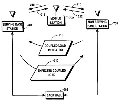
load and the reverse link coupled. load, as well as other factors, to
determine the .
appropriate load scheduling. For most data applications, however, mobile
stations are
controlled by, a single Serving base station to reduce scheduling delays
although the
reverse link transmissions can affect the load at other base stations.
=
CA 02529554 2005-12-14
WO 2004/114705
PCT/US2004/018995
2
[0004] Conventional systems, however, are limited in several ways. For
example, the
communications with the centralized controller result in significant delays.
Information
gathered by each base station is forwarded to the centralized controller. The
centralized
controller processes the information, determines an optimum load capacity for
each base
station, and sends the optimum load capacity to each of the base stations.
Each base
station limits the communications of the mobile stations that it is serving in
accordance
with the updated load capacity provided by the controller. The channel
conditions,
however, often change during the time that is required to transmit, process,
and receive
the optimum load capacity. Accordingly, a base station may be operating at a
level
significantly different from the optimum level resulting in unused resources
or an
overload condition. An overload condition may occur, for example, where a base
station
operating in accordance with the latest optimum capacity information that was
provided
by the controller may overload another base station that is attempting to
operate near its
maximum capacity because delays in the system have not allowed the new channel
conditions to be reflected in the information conveyed to the base stations.
Overload
conditions lead to lost data, re-transmissions of messages, and other
undesired
consequences.
[0005] Accordingly, there is need for an apparatus, system, and method
for efficiently
allocating reverse channel resources in a communication system with
geographically
distributed base stations.
BRIEF DESCRIPTION OF THE DRAWINGS
[0006] FIG. 1 is a block diagram of communication system having
geographically
' distributed base stations in accordance with the exemplary embodiments of
the
invention.
[0007] FIG. 2 is a block diagram of a portion of the communication system
where a
single mobile station is in communication with base stations functioning as a
serving
base station and a non-serving base station.
[0008] FIG. 3 is a block diagram of a base station in accordance with an
exemplary
embodiment of the invention.
[0009] FIG. 4 is a block diagram illustrating an exemplary relationship
between the
mobile stations and the base stations in accordance with the exemplary
embodiments of
the invention.
CA 02529554 2005-12-14
WO 2004/114705
PCT/US2004/018995
3
[0010] FIG. 5 is a table illustrating the exemplary relationship between
the mobile
stations and the base stations in accordance with the exemplary embodiments of
the
invention.
[0011] FIG. 6 is a graphical illustration of an exemplary distribution of
reverse link
loads and reverse link coupled loads experienced at a base station in
accordance with the
exemplary embodiments of the invention.
[0012] FIG. 7 is a block diagram of a portion of the communication system
in
accordance with the first exemplary embodiment of the invention.
[0013] FIG. 8 is a flow chart of a method of determining an expected
coupled load
performed at a serving base station in accordance with the first exemplary of
the
invention.
[0014] FIG. 9 is a flow chart of a method of determining an available
capacity at a non-
serving base station in accordance with the first exemplary embodiment of the
invention.
[0015] FIG. 10 is a flow chart of managing reverse link channel resources
in the
communication system in accordance with the first exemplary embodiment of the
invention.
[0016] FIG. 11 is a block diagram of a portion of the communication system
in
accordance with a second exemplary embodiment of the invention.
[0017] FIG. 12 is a flow chart of a method of managing reverse link
channels performed
in a base station functioning as a serving base in accordance with the second
exemplary
embodiment of the invention.
[0018] FIG. 13 is a flow chart of a method of managing reverse link
channel resources
at a base station functioning as a non-serving base station in accordance with
the second
exemplary embodiment of the invention.
[0019] FIG. 14 is a flow chart of a method of allocating reverse link
channel resources
in a communication system having geographically distributed base stations in
accordance with the second exemplary embodiment of the invention.
[0020] FIG. 15 is a block diagram of a portion of a communication system
providing
communications services to mobile stations with geographically distributed
base stations
in accordance with the third exemplary embodiment of the invention.
CA 02529554 2012-04-26
74769-1257
4
[0021] FIG. 16 is a flow chart of a method, performed in a base
station, of
managing reverse link resources in a communication system having
geographically
distributed base stations in accordance with the third exemplary embodiment of
the
invention.
DETAILED DESCRIPTION OF THE PREFERRED EMBODIMENTS
[0021a] According to one aspect of the present invention, there is
provided a
method, performed in a base station functioning as a non-serving base station
to at
least one mobile station served by another base station, for allocating
reverse link
resources to mobile stations served by the base station in a distributed base
station
communication system, the method comprising: measuring coupled load parameters
of reverse link transmissions of the at least one mobile station served by
another
base station; calculating an estimated expected coupled load due to reverse
link
transmissions of the at least one mobile station based on the coupled load
parameters; allocating reverse link resources to other mobile stations served
by the
base station in accordance with the estimated expected coupled load.
[0021b] According to another aspect of the present invention, there is
provided
a method, performed in a base station in a distributed base station
communication
system, the method comprising: measuring coupled load parameters of reverse
link
transmissions of mobile stations served by other base stations; calculating a
total
coupled load for a previous transmission period based on the coupled load
parameters, the total coupled load representing a total load contribution due
to
reverse link transmissions of the mobile stations; calculating an estimated
expected
coupled load for a current transmission based on the total coupled load;
calculating a
total available capacity of the base station by subtracting the estimated
expected
coupled load from a total capacity of the base station; and allocating reverse
link
resources to other mobile stations served by the base station in accordance
with the
total available capacity.
[0021c] According to still another aspect of the present invention,
there is
provided a processor for a base station of a distributed base station
communication
CA 02529554 2012-04-26
74769-1257
4a
system the processor configured to: calculate a total coupled load based on
measured coupled load parameters of reverse link transmissions of mobile
stations
served by other base stations for a previous transmission period based on the
coupled load parameters measured at the base station; calculate an estimated
expected coupled load for a current transmission period based on the total
coupled
load; and calculating a total available capacity of the base station by
subtracting the
estimated expected coupled load from a total capacity of the base station.
[0021d] According to another aspect of the present invention, there is
provided
an apparatus in a base station functioning as a non-serving base station to at
least
one mobile station served by another base station, for allocating reverse link
resources to mobile stations served by the base station in a distributed base
station
communication system, the apparatus comprising: means for measuring coupled
load
parameters of reverse link transmissions of the at least one mobile station
served by
another base station; means for calculating an estimated expected coupled load
due
to reverse link transmissions of the at least one mobile station based on the
coupled
load parameters; means for allocating reverse link resources to other mobile
stations
served by the base station in accordance with the estimated expected coupled
load.
[0021e] According to another aspect of the present invention, there is
provided
a processor-readable medium having processor-executable instructions stored
thereon that, when executed by a processor, cause the processor to implement a
method to cause a base station functioning as a non-serving base station to at
least
one mobile station served by another base station, to allocate reverse link
resources
to mobile stations served by the base station in a distributed base station
communication system, the method comprising the steps of: measuring coupled
load
parameters of reverse link transmissions of the at least one mobile station
served by
another base station; calculating an estimated expected coupled load due to
reverse
link transmissions of the at least one mobile station based on the coupled
load
parameters; allocating reverse link resources to other mobile stations served
by the
base station in accordance with the estimated expected coupled load.
CA 02529554 2012-04-26
74769-1 257
4b
100221 An apparatus, system, and method manage reverse link communication
in a
distributed base station commtmication system. In the exemplary embodiments
discussed herein, reverse link communication is distributively managed by base
stations
within a communication system. Delays associated with conventional techniques
for
managing reverse link channels are avoided since the reverse link management
is not
dependent on communications with a central controller. In a first exemplary
embodiment, a non-serving base station determines a coupled load indicator
based on
coupled load parameters detected at the non-serving base station due to a
mobile station
that has identified another base station as the serving base station. The
coupled load
parameters are parameters that provide an indication of the coupled load
experienced at
the non-serving base station and may include parameters such as a normalized
and
averaged received signal-to noise ratio (SNR) and a mobile station speed. A
coupled
load indicator based on the coupled load parameters is forwarded to the
serving base
station. The serving base station calculates an expected coupled load at the
non-serving
base station based on the coupled load indicator and a mobile station
transmission
parameter such as a scheduled transmission data rate. The expected coupled
load is
forwarded to the non-serving base station, where the non-serving base station
calculates
the available capacity by accounting for the expected coupled load. Mobile
stations
sewed by the non-serving base station are load scheduled in accordance with
the
calculated available capacity.
[00231 In a second exemplary embodiment, a non-serving base station
calculates the
maximum tolerable coupled load due to the mobile stations that are scheduled
by some
other serving base station. The non-serving base station determines a coupled
load
indicator based on coupled load parameters (such as a normalized and averaged
receive
signal-to noise ratio (SNR)) at the non-serving base station due to every
mobile station
that has identified some other base station as the serving base station. In
the second
exemplary embodiment, the maximum tolerable coupled load associated with the
non-
.
CA 02529554 2005-12-14
WO 2004/114705
PCT/US2004/018995
serving base station is forwarded to the serving base station every scheduling
period and
the measured coupled load indicators of mobile stations are forwarded to the
serving
base station at a relatively lower frequency. Since the serving base station
under
consideration may also be a non-serving base station for some other mobile
stations, the
serving base station also determines a maximum tolerable coupled load from the
mobile
stations that are served by other base stations. The base station performs
load scheduling
in accordance with the maximum tolerable coupled load reserved for mobile
stations not
being scheduled by the base station while meeting the constraints imposed by
the
maximum tolerable coupled load received from other base stations.
[0024] In a third exemplary embodiment of the invention, a serving base
station
schedules the mobile station reverse link transmissions in accordance with an
estimated
expected coupled load due to reverse link transmissions of mobile stations
served by
other base stations. Each base station estimates the expected coupled load due
to mobile
stations served by other base stations. Based on the estimated coupled load
and the
capacity of the base station, the base station load schedules the mobile
stations served by
the base station. In the third exemplary embodiment, therefore, the base
stations do not
receive explicit or direct coupled load information from other base stations.
Accordingly, the third exemplary embodiment is particularly useful where the
backhaul
does not support communication of coupled load information between base
stations.
Although any of several techniques may be used to calculate the estimated
coupled load,
the estimations are based on previous reverse link transmissions of the mobile
stations
in the third exemplary embodiment. Each base-station measures the coupled load
from
the mobile stations not being scheduled by the base station based on the
actual
transmission rates and the measured SNR. The previous measurements of coupled
load
are fed to a statistical function that estimates the expected coupled load
during the next
scheduled transmission. The statistical function relies on the correlation
that may, in
some circumstances, be adaptively modified. The "blind" determination of the
expected
coupled load, within a certain margin, determines the available capacity
available for the
base station to schedule mobile stations served by the base station.
[0025] FIG. 1 is a block diagram of a communication system 100 providing
wireless
communication services to mobile stations 110, 112, 114 using geographically
distributed base stations 102, 104, 106, 108 in accordance with the exemplary
embodiments of the invention. FIG. 2 is a portion 200 of the communication
system 100
CA 02529554 2005-12-14
WO 2004/114705 PCT/US2004/018995
6
where a single mobile station 202 is in communication with base stations (102-
108)
functioning as a serving base station 204 and non-serving base station 206 to
the mobile
station 202. At any particular time, a base station (102-108) may function as
a serving
base station 204 or a non-serving base station 206 to a particular mobile
station (110-
114) or may not perform any function directly for the mobile station (110-
114). In the ,
interest of clarity, four base stations 102, 104, 106, 108 and three mobile
stations 110,
112, 114 are represented in FIG. 1. The communications system may include any
number of base stations (102-108) and mobile stations (110-114) as well as
other
communication equipment. In the exemplary embodiments presented, the
communication system 100 is a cellular communication system utilizing code
division
multiple access (CDMA) communication techniques to provide voice and data
services.
Those skilled in the art will readily recognize the various other types of
communication
systems 100 suitable for use with the invention by applying the teachings
herein in
accordance with known techniques.
[0026] Each base station 102, 104, 106, 108 provides wireless
communication service to
mobile stations (110, 112, 114) in a coverage region 116, 118, 120, 122 or
cell. The
coverage regions 116-120 overlap such that a mobile station 110-114 may be in
communication with more than one base station 102-108 at any one time. If a
mobile
station 110-114 is within the coverage region of a base station 102-108, the
mobile
station 110-114 will identify the base station 102-108 as an active base
station. As
discussed in further detail below, however, only one base station (102-108)
functions as
a serving base station 204 to a particular mobile station 202 (110-114) for
data
communications. A serving base-station 204 is the base station responsible for
scheduling the next transmissions of a mobile station 202. FIG. 1 includes
exemplary
shapes surrounding each base station 102-108 representing serving regions 116,
118,
120, 122 where the base station 102-108 is most likely to function as the
serving base
station 204 for the mobile stations 202 (110-114) within the serving region
116-122.
Each mobile station 110-114 maintains a set of active base stations in memory
where
members of the set communicate through communication links that satisfy the
required
criteria. An example of a suitable method for selecting the active base
stations (102-108)
for a mobile station 110-114, 202 includes identifying a base station 102-108
as an
active base station (102-108) 204, 206 when a signal transmitted from the base
station
102-108 is received at the mobile station 110-114 at an adequate level. In the
exemplary
CA 02529554 2005-12-14
WO 2004/114705 PCT/US2004/018995
7
embodiments, the active base stations (102-108) 204, 206 are selected based on
the
received signal strengths of pilot signals transmitted from the base stations
102-108,
204, 206. In some circumstances, other techniques may be used to select the
active base
stations (102-108) 204, 206. The active base stations (102-108) 204, 206
provide
communication service to a mobile station 110-114, 202 where the quality of
service
and data rate may vary between the base stations 102-108 due to various
reasons.
[0027] In the exemplary embodiment, one of the active base stations (102-
108) is
selected as a serving base station 204 for the communication of data other
than voice
information. Any of several techniques and criteria may be used to select the
serving
base station 204. The serving base station 204 may be selected based on
characteristics
of the forward communication link 210 (from the base station 102-108 (204) to
the
mobile station 110-114 (202)), the reverse communication link 212 (from the
mobile
station 110-114 (202) to the base station 102-108 (204)) or on both the
reverse and
forward communication links 212, 210. The quality of the forward and reverse
link
channels 210, 212, for example, may be determined by measuring the carrier to
interference ratio of the channel. In the exemplary embodiment, information
contained
in a reverse link channel quality indicator channel is used to identify the
serving base
station 204 and is identified by the R-CQICH channel. The serving base station
204
responds to the communications from the mobile stations 202 it is serving by
performing various tasks such as allocating data transmissions rates via
scheduling
grants and maintaining reverse-link pilot received SNR above a threshold by
sending
power control commands. In addition, a serving base station 204 decodes the
transmissions from the mobile station 202 and sends acknowledgements in case
of
hybrid-ARQ while a non-serving base station may also decode a transmission and
send
an ACK in case of a soft-handoff. The enclosed shapes representing the
coverage
regions in FIG. 1 define exemplary geographic serving regions 116-122 where
mobile
stations 110-114 within the region 116-122 will likely have adequate
communication
with the corresponding base station 102-108 to identify the particular base
station 102-
108 as the serving base station 204. Other base stations (102-108), however,
may
perform as active base stations (102-108) 206 to a mobile station 110-114,
202. As
illustrated in FIG. 1, therefore, a first mobile station 110 is within a first
serving region
116 provided by the first base station 102, a second mobile station 112 is
within a
second serving region 118 provided by the second base station 104, a third
mobile
CA 02529554 2005-12-14
WO 2004/114705
PCT/US2004/018995
8
station 114 is within a third serving region 129 provided by the third base
station 106,
and the fourth base station 108 provides a fourth serving region 122.
[0028] FIG. 3 is a block diagram of a base station 300 in accordance with
an exemplary
embodiment of the invention. The exemplary base station 300 is suitable for
use as any
one of the base stations 102-108, 204, 206 discussed with reference to FIG. 1
and FIG.
2. The base station 300 may include any combination of hardware, software, and
firmware that performs the functions to the base stations 102-108. The
functions and
operations of the blocks described in FIG. 3 may be implemented in any number
of
devices, circuits, or software. Two or more of the functional blocks may be
integrated in
a single device and the functions described as performed in any single device
or block
may be implemented over several devices. For example, some receiving processes
may
be performed by the processor 304.
[0029] The base station includes a radio transceiver 302 configured to
communicate
with mobile stations 110-114 in accordance with the protocols of the
particular
communication system 100. Radio frequency signals are exchanged through the
antenna
308 which may include sectors in some circumstances. The radio transceiver 302
modulates, amplifies, and transmits signals through the forward link channels
212 and
receives and demodulates reverse link signals transmitted by the mobile
stations 110-
114 through the reverse link channels 210.
[0030] The processor 304 is any processor, microprocessor, computer,
microcomputer,
or processor combination suitable for performing the control and calculation
functions
of the base station 300 described herein as well as facilitating the overall
functionality of
the base station 300. Software code running on the processor 304 executes the
steps of
methods for measuring and processing signals and for performing the reverse
link
management functions of the exemplary embodiments.
[0031] A backhaul interface 306 provides an interface to the backhaul 208
of the
communication system 100. The backhaul interface 306 includes hardware and
software
for exchanging signals through the backhaul 208. The processor 304 transmits
and
receives information to and from controllers and other base stations 102-108
through the
backhaul interface 306.
[0032] FIG. 4 is a block diagram and FIG. 5 is table 500 illustrating an
exemplary
relationship between the mobile stations 110-114 and the base stations 102-108
in
accordance with the exemplary embodiments of the invention. The solid lines
CA 02529554 2005-12-14
WO 2004/114705 PCT/US2004/018995
9
connecting base stations 102-108 to mobile stations 110-114 in FIG. 4
represent a
connection between mobile stations 202 (one of 110-114) and their
corresponding
serving base stations 204 (one of 102-108) and dashed lines represent
connections
between mobile stations 202 (one of 110-114) and their non-serving active base
stations
206 (one of 102-108). As discussed herein, a non-serving active base station
206 (102-
108) is a base station 300 identified in the set of active base stations of a
mobile station
202 that is not a serving base station 204. In the exemplary situation
illustrated in FIG. 4
and FIG. 5, each mobile station 110-114 maintains a set of active base
stations that
includes the serving base station 204 corresponding to the serving region 116-
122
containing the mobile station 110-114 and all other base stations (102-108)
that are non-
serving active base stations (102-108). Accordingly, for the exemplary
situation, all of
the base stations 102-108 are maintained as active base stations by each of
the mobile
stations 110-114. A mobile station as a significant distance from a base
station may not
maintain the base station in the set of active base stations and the base
station will not be
identified as a non-serving base station to the mobile station even though the
base
station may receive reverse link interference from the mobile station. Only
those mobile
stations whose signal strength is strong enough and their transmissions
processed are
considered by a base-station. Focusing briefly on a single mobile station 110,
the first
base station 102 is the serving base station 204 for the first mobile station
110, 202, and
the second base station 104, third base station 106 and fourth base station
108 are non-
serving base stations 206 for the first mobile station 110, 202. The reverse
link
transmissions of each of the mobile stations 110-114, therefore, are received
at each of
the base stations 102-108 although only one of the base stations 102-108 that
is
performing as the serving base station 204 and the other base stations are
performing as
non-serving (active) base stations 206 for any particular mobile station 110-
114 in this
example. As a result, the reverse link loads and reverse link coupled loads
experienced
at a base station 102 are due to the reverse link loads of the mobile station
110 served by
the base station 102 and the coupled loads resulting from transmission of
other mobile
stations .112, 114.
[0033] FIG. 6 is an illustration of a load pie chart 600 of an exemplary
distribution of
reverse link loads and reverse link coupled loads experienced at a base
station 102-108
in accordance with the exemplary embodiments of the invention. The various
sections
602-608 of the load pie chart represent the combined reverse link load
resulting from
CA 02529554 2005-12-14
WO 2004/114705 PCT/US2004/018995
mobile stations 110-114 that can be measured or simulated for an exemplary
situation.
At any base station 102-108, the total combined reverse link load may result
from
transmissions from mobile stations 110-114 where each portion (602-608) of the
total
reverse link load is due to mobile stations (110-114) in a particular
category. The load
portions (602-608) may include a non-serving coupled load portion 602, a
serving non-
single load portion 604, a serving single portion 606, and an unaccounted
coupled load
portion 608. The non-serving coupled load portion 602 includes the coupled
reverse link
load due to all of the mobile stations (110-114) that include the base station
(102-108)
within their set of active base stations but that are being served by base
stations (102-
108) other than the base station (102-108). The mobile stations 110-114
contributing to
the non-serving coupled load portion 602, therefore, have not identified the
base station
(102-108) as the serving base station 204.
[0034] The non-single serving load portion 604 includes the combined
reverse link load
of all mobile stations 110-114 that are being served by the base station (102-
108) but
include other base stations (102-108) in their list of active base stations.
The mobile
stations 110-114 contributing to the non-single serving load portion 604,
therefore, have
identified the base station (102-108) as the serving base station but also
have identified
other base stations (102-108) as non-serving active base stations.
[0035] The single serving load portion 606 includes the combined
reverse link load of
all mobile stations served by the base station (102-108) where the base
station (102,108)
is the only base station in the set of active base stations of any of the
mobile stations
110-114.
[0036] The unaccounted load portion 608 includes all other reverse link
signals and
noise that contribute to the total reverse link load that has not been
included in any of
the other load portions 602, 604, 606. An example of a source that may
contribute to the
unaccounted load portion 608 includes the reverse link transmissions from
mobile
stations that do not include the base station in their active set but are
sufficiently close to
the base station to contribute to total coupled load. Such mobile stations are
too far to
have an adequate communication link with the base station to include the base
station in
the set of active base station but the sum total of their insignificant
contributions is large
enough to take a share in the reverse-link capacity.
[0037] The relative size of the load portions 602-608 will vary over
time in most
situations because of the constantly changing channel conditions. The changing
channel
CA 02529554 2005-12-14
WO 2004/114705 PCT/US2004/018995
11
conditions may be due to several factors such as the motion of the mobile
stations 110-
114, the motion of obstacles, or the need to offload mobile stations 110-114
and to
transfer mobile stations between base stations due to severely non-uniform
distribution
of mobile stations 110-114. When the combined load of all of the portions 602-
608
exceeds the capacity of the base station 102-108, the quality of service (QoS)
to the
mobile stations suffers, the system becomes slightly unstable and coverage of
the cell
decreases leading to call drops. Where the load is less than the capacity of
the base
station 102-108, an inefficient use of resources can occur if the data rates
are not
adjusted in accordance with the requests of the mobile stations 110-114. In
accordance
with the exemplary embodiments, the reverse link communications are managed by
the
base stations 102-108 to efficiently allocate reverse link resources to (load
schedule) the
mobile stations 110-114. Reverse link resources include, for example, data
rates and
power levels that contribute to a load to the base station 102-108.
[0038] FIG. 7 is a block diagram of a portion 700 of a communication
system 100
providing communications services to mobile stations 110-114 with
geographically
distributed base stations 102-108 in accordance with the first exemplary
embodiment of
the invention. In most situations, the communication system 100 includes
several base
stations 704, 706 that are strategically positioned to provide wireless
communication
services to numerous mobile stations 702. Depending on the quality of the
communication channels between a mobile station 702 and the base station
(704,706),
the mobile station 702 may be communicating with more than one base station
(704,
706) at any particular time. As discussed above, each mobile station 702
maintains a set
of active base stations where the communication links between the mobile
station 702
and the active base stations 704, 706 are adequate for communication. Of the
active base
stations, one base station performs as the serving base station 704 while the
other base
stations in the active set are non-serving base stations 706. Such situations
typically
occur during a soft handoff where a single base station performs the functions
of a
serving base station 704 and one or more other base stations are non-serving
active base
stations 706. Where conditions warrant, the role of the serving base station
704 is
transferred to a base station previously functioning as a non-serving active
base station
706 (i.e. a handoff occurs).
[0039] In the interest of clarity, FIG. 7 includes blocks representing a
mobile station 702
and two active base stations 704, 706 including a serving base station 704 and
non-
CA 02529554 2005-12-14
WO 2004/114705 PCT/US2004/018995
12
serving base station 706. Those skilled in the art will recognize, based on
these
teachings and known techniques, that a base station 300 may function as a
serving base
station 704 to numerous mobile stations 702 and that any one mobile station
702 may
maintain any number of active base stations 704, 706. The teachings discussed
herein,
therefore, may be extended to any number of mobile stations 702, serving base
stations
704, and non-serving base stations 706. As discussed below in further detail,
the other
base stations 300 may not have a communication link with the mobile station
702 of
sufficient quality to become an active base station but may contribute to the
load
experienced at any one of the active base stations 704, 706. The serving base
station 704
may be the first base station 102, the second base station 104, or third base
station 106
discussed above with reference to FIG.s 1-4. The serving base station 704 may
also
function as a non-serving base station 706 for another mobile station (not
shown in FIG.
7) and the non-serving base station 706 may function as a serving base station
704 for
other mobile stations (not shown in FIG. 7). Accordingly, a base station 102-
108 may
simultaneously function as a serving base station 704 to some mobile stations
702 and
as a non-serving base station to other mobile stations. The functions
described herein for
each of the base stations 704, 706, therefore, are simultaneously performed by
the other
of the base stations in most circumstances.
[0040] In the first exemplary embodiment, a base station 300 functioning
as the non-
serving base station 706 determines an expected available capacity based on an
expected
coupled load 712 received from another base station 300 functioning as the
serving base
station 704 where the expected coupled load 712 indicates an expected coupled
load at
the non-serving base station 706 resulting from reverse link transmissions 210
of a
' mobile station 702 being served by the serving base station 704. The serving
base
station 704 determines the expected coupled load 712 using the coupled load
indicator
710 received from the non-serving base-station 706 and the parameters
associated with
the next scheduled data transmission rate. If there are multiple mobile
stations 702 that
are served by the serving base station 704 and that include the non-serving
base-station
706 as a non-serving base station, the expected coupled load 712 can be the
sum of
expected coupled loads determined for each of the mobile stations based on the
expected coupled load 712 and scheduled transmission data rates. The non-
serving base
station 706 receives and processes the reverse link transmissions 210 of the
mobile
station 702 to determine one or more coupled load parameters a such as a
normalized
CA 02529554 2005-12-14
WO 2004/114705
PCT/US2004/018995
13
and averaged receive signal-to noise ratio (SNR). An example of another
coupled load
parameter is a speed of the mobile station 702. Based on the coupled load
parameters,
the non-serving base station 706 calculates the coupled load indicator 710.
The coupled
load indicator 710 is forwarded to the serving base station 704. The serving
base station
704 determines an expected coupled load at the non-serving base station 706
using the
coupled load indicator 710 and a transmission parameter of the mobile station
702. The
expected coupled load is the coupled reverse link load that will result at the
non-serving
base station 706 due to an anticipated future reverse link transmission of the
mobile
station 702. The serving base station 704 forwards a value representing the
expected
coupled load 712 to the non-serving base station 706. The non-serving base
station 706
calculates the expected available capacity at the non-serving base station
706. Using the
expected available capacity, the non-serving base station 706 manages the
reverse link
transmissions of other mobile stations (not shown) that are served by the non-
serving
base station 706 by appropriately load scheduling the mobile stations it is
serving.
Where there is more than one mobile station 702, the non-serving base station
706
measures and computes a coupled load indicator 710 for each mobile station 702
that
maintains the non-serving base station 706 within the active set. A coupled
load
indicator 710 is forwarded to each serving base station 704 associated with
the mobile
stations 702 that identify the non-serving base station 706 as an active base
station.
[0041] In the first exemplary embodiment, the coupled load indicator 710
is an energy-
per-chip-to-noise-plus-interference ratio (Ecp/Nt), where Ecp represents the
energy per
pilot signal chip. If the reverse link pilot is power controlled, an average
expected
(Ecp/Nt) is computed by averaging chip (Ecp/Nt) over a particular duration.
The
coupled load indicator 710 may be the average expected (Ecp/Nt) or any
function of the
average expected (Ecp/Nt).
[0042] Although other methods may be used in some circumstances to
forward the
coupled load indicator 710 to the serving base station 704, the coupled load
indicator
710 is transmitted through the backhaul 208 in the first exemplary embodiment.
Accordingly, appropriate messaging and addressing is used to rout the coupled
load
indicator 710 through the backhaul 208. The backhaul interface 306 performs
any
required translations, or processing to exchange the coupled load indicators
through the
backhaul. In some circumstances, the coupled load indicator 710 can be
transmitted
through a direct communication link between the non-serving base station 706
and the
CA 02529554 2005-12-14
WO 2004/114705 PCT/US2004/018995
14
serving base station 704. For example, a radio frequency or microwave point-to-
point
system link can be used to transmit coupled load indicator 710 in some
situations.
Further, in some circumstances, the coupled load indicator 710 may be conveyed
through the mobile station 702.
[0043] In the first exemplary embodiment, the serving base station 704
identifies the
mobile stations 702 that are expected to transmit during the next transmit
cycle and
generates the expected coupled load 712 based on the coupled load indicators
710 (for
example Ecp/Nt) received from the non-serving base station 706 and the
transmission
data rate that the mobile station 702 has been authorized (scheduled) to use
during the
next transmission. The transmission parameter, therefore, at least includes
the
anticipated data rate of the mobile station 702 in the first exemplary
embodiment. In
addition, other transmission parameters may be used to calculate the expected
coupled
load at the non-serving base station 706, such as secondary pilot
transmissions or
control channels traffic-to-pilot ratio. In scenarios where the autonomous
transmission
on control and voice channels take place, the expected coupled load 712 may
account
for the average expected coupled load contributed by these channels. In the
first
exemplary embodiment, the expected coupled load 712 is some function of the
expected
Ecp/Nt that will be experienced by the non-serving base station 706 in the
anticipated
future transmission of the mobile station 702 and other transmission
parameters
including the scheduled transmission data rate. The serving base station 704
generates
the expected coupled load 712 based on the coupled load indicator 710 and
forwards the
expected coupled load 712 to the non-serving base station 706. The expected
coupled
load 712, therefore, is based on the measured Ecp/Nt at the non-serving base
station
704, the reverse link transmission power on control and voice channels, and
the data rate
on the traffic channel of the mobile station 702 in the first exemplary
embodiment. The
expected coupled load 712, however, may represent other values in some
circumstances.
For example, the expected coupled load 712 my represent an expected change in
the
coupled load that will be experienced at the non-serving base station as
compared to a
previous transmission.
[0044] Where the serving base station 704 is serving more than one mobile
station 702
that has included at least one other non-serving base station 706 within the
set of active
base stations, the serving base station 704 generates an expected coupled load
712 for
each non-serving base station 706 that has forwarded a coupled load indicator
710 to the
CA 02529554 2005-12-14
WO 2004/114705
PCT/US2004/018995
serving base station 704. Accordingly, any particular base station 300
functioning as a
non-serving base station 706 may receive an expected coupled load 712 from any
number of base stations 300 functioning as serving base stations 704.
[0045] In the first exemplary embodiment, the expected coupled load 712 is
transmitted
through the backhaul 208 to the non-serving base station 704. The backhaul
interface
306 performs the required processing and formatting to transmit the expected
coupled
load 712 through the backhaul 208 to the base station 300 functioning as the
non-
serving base station 704. In some situations, other techniques may be used to
forward
the expected coupled load 712.
[0046] After a base station 300 has received the expected coupled load 712
from all of
the appropriate serving base stations 704 of mobile stations 702 contributing
to the non-
serving coupled load portion 602 of the total load, the non-serving base
station 706
(300) determines the available capacity. The total of all of the expected
coupled loads
712 is the expected non-serving coupled load portion of the total load at the
base station
300. The available capacity is the difference of the total capacity of the non-
serving base
station 706 (300) and the total of the expected non-serving coupled load
portion (402),
and the unaccounted load portion 408. After taking into account loads due to
voice or
fundamental reverse channel traffic, the available capacity (CAV) at a base
station 300
can therefore be expressed as:
CAV = CTOT ¨ (LoadFx + LoadUA)
where CTOT is the total capacity of the cell after taking into account the
loads due to voice and fundamental reverse channel traffic; LoadEx is the
expected non-
serving coupled load due to the mobile stations that are served by other base
stations and
for which the base station is included in the set of active base stations; and
LoadUA is
the load due to other sources.
[0047] Using the available capacity, the base station 300 functioning as a
non-serving
base station 706 for the mobile station 702 allocates reverse link resources
(load
schedules) the mobiles stations (not shown) that it is serving. In the
exemplary
embodiment, the non-serving base station 706 load schedules the mobile
stations that do
not have any other base stations in their active base station after allocating
resources to
the mobile stations maintaining other active base stations.
[0048] FIG. 8 is flow chart of a method of determining an expected coupled
load
performed at a base station 300 functioning as a serving base station 704 to
at least one
CA 02529554 2005-12-14
WO 2004/114705 PCT/US2004/018995
16
mobile station 702 in accordance with the first exemplary of the invention. In
some
circumstances, the method discussed in FIG. 8 is performed in a base station
300 that is
also functioning as a non-serving base station 706. The method described with
reference
to FIG. 8 is performed where at least one non-serving base station 706 is
maintained in
the set of active base stations of at least one mobile station 702 that is
being served by
the serving base station 704. The techniques discussed herein can be applied
to any
number of base stations 300 and mobile stations 110-114. In the exemplary
embodiments, the methods are performed at least partially with software code
running
on the processor 304 within one or more base stations 300. Those skilled in
the art will
readily recognize the various techniques that can be sued to implement the
methods
discussed based on the teachings herein in accordance with known techniques.
[0049] At step 802, a coupled load indicator 710 is received from a base
station 300
functioning as a non-serving base station 706 to at least one mobile station
702. The
coupled load indicator 710 indicates the coupled load measured at the non-
serving base
station 706 due to the mobile station 702 served by another base station 300
functioning
as the serving base station 704 to the mobile station 702. The non-serving
base station
706 is included within the set of active base stations maintained by the
mobile station
702. In the first exemplary embodiment, the coupled load indicator 710
represents the
ECP/NT measured at the non-serving base station 706.
[0050] At step 804, the serving base station 704 determines an expected
coupled load
712 at the ,non-serving base station 706 due to the mobile station 702 based
on the
coupled load indicator 710 and at least one transmission parameter. In the
first
exemplary embodiment, the serving base station 704 calculates the expected
coupled
load 712 for the mobile stations 702 that are expected to transmit on the next
transmission based on the coupled load indicator 710 measured at the non-
serving base
station 706, the mobile station's scheduled data transmission rate for the
future
anticipated transmission, and the transmission power level of the mobile
station 702.
The expected coupled load, therefore, is the expected load to the non-serving
base
station 706 due to reverse link transmissions of the mobile station 702 that
includes at
least the serving base station 704 and the non-serving base station 706 in the
mobile
station's list of active base stations.
[0051] At step 806, the expected coupled load 712 is forwarded to the base
station 300
functioning as the non-serving base station 706 to the mobile station 702. In
the first
CA 02529554 2005-12-14
WO 2004/114705 PCT/US2004/018995
17
exemplary embodiment, the expected coupled load 712 represents the expected
loading
as a function of the scheduled transmission data rate and the expected ECP/Nt
level at
the non-serving base station 706 due to a future anticipated transmissions of
the mobile
station 702. The expected coupled load 712, however, may represent other
parameters or
values. For example, the expected coupled load 712 may represent an
anticipated change
in the load experienced at the non-serving base station 706 due to the future
transmission of the mobile station 702 as compared to a previous transmission.
In the
first exemplary embodiment, the expected coupled load indicator 712 is
formatted to
conform to the appropriate protocol and is transmitted through the backhaul
208 of the
communication system 100. The expected coupled load indicator 712 may be
forwarded
to the non-serving base station 706 using other techniques. For example, a
direct link
communication link between the serving base station 704 and the non-serving
base
station 706, such as point-to-point microwave link, can be used to convey the
expected
coupled load.
[0052] FIG. 9 is a flow chart of a method of determining an available
capacity at a base
station 300 functioning as a non-serving base station 706 in accordance with
the first
exemplary embodiment of the invention. In some circumstances, the method
discussed
in FIG. 9 is performed in a base station 300 that is also functioning as a
serving base
station 704 to other mobile stations 110-114. The method described with
reference to
FIG. 9 is performed where the set of active base stations maintained at least
at one
mobile station 702 includes the non-serving base station 706 and a serving
base station
704. The techniques discussed herein can be applied to any number of base
stations 300
and mobile stations 110-114.
[0053] At step 902, an expected coupled load 712 is received from a base
station 300
functioning as a serving base station 704 of a mobile station 702 that
maintains a set of
active base stations that includes at least the non-serving base station 706
and the
serving base station 704. As discussed above, the expected coupled load 712
represents
the expected coupled load that will likely be experienced at the non-serving
base station
706 due to an anticipated future transmission of the mobile station 702.
[0054] At step 904, the base station 300 functioning as the non-serving
base station 706
determines the available capacity at the non-serving base station 706 based on
the
expected coupled load 712. After taking into account the voice and non-
scheduled
reverse traffic data, the non-serving base station 706 determines the
available capacity
CA 02529554 2005-12-14
WO 2004/114705 PCT/US2004/018995
18
by calculating the difference between the total capacity and the sum of all
loads and
expected coupled loads. The remainder indicates the available capacity of the
non-
serving base station 706 that can be used for mobile stations 110-114 that the
non-
serving station 706 may be serving as a serving base station.
[0055] At step 906, the base station 300 functioning as the non-serving
base station 706
allocates reverse link channel 212 resources (load schedules) mobile stations
110-114
served by the base station 300 functioning as the non-serving base station 706
to the
mobile station 702 in accordance with the available capacity. The non-serving
base
station 706 allocates the available capacity by limiting power levels and data
rates of any
mobile stations 110-114 that are being served by the non-serving base station
706.
[0056] In the exemplary embodiment, the methods described with reference
to FIG. 8
and FIG. 9 are performed within several geographically distributed base
stations 300
where any of the base stations 300, at any time, may be functioning solely as
a serving
base station 704, solely as an non-serving base station 706, or as both a
serving base
station 704 for one or more mobile stations 110-114 and a non-serving base
station 706
for one or more other mobile stations 110-114. Further, a mobile station 702
may
maintain a set of active base stations that includes several non-serving base
stations 706
in addition to the serving base station 704. Accordingly, in order to
efficiently mange
the reverse link loads at the various base stations 300, the coupled load
indicators 710
and expected coupled loads 712 are conveyed to the appropriate base stations
300 and
the calculations are performed taking into account the various parameters
received from
multiple base stations 300.
[0057] FIG. 10 is a flow chart of a method of allocating reverse link
channel resources
in a communication system 100 having geographically distributed base stations
300 in
accordance with the first exemplary embodiment of the invention. As discussed
above,
the functions of serving base stations 704 and non-serving base stations 706
may be
performed within a single base station 300 that functions as serving base
station 704 to
some mobile stations 110-114 and as a non-serving active base station 706 to
other
mobile stations 114.
[0058] At step 1002, the base stations 300 functioning as serving base
stations 704
receive coupled load indicators 710 measured at base stations 300 functioning
as non-
serving base stations 706 where the coupled loads are due to the reverse link
transmissions from mobile stations 702 served by the serving base stations 704
and that
CA 02529554 2005-12-14
WO 2004/114705 PCT/US2004/018995
19
maintain a set of active base stations that include the one or more of the non-
serving
base stations 706. Each non-serving base station 706 generates a coupled load
indicator
710 that, along with the rate of transmission, represents the measured coupled
load at
the non-serving base station 706 due to the mobile stations that are served by
another
base station 300. The coupled load indicators 710 are transmitted by the non-
serving
base stations 706 to the corresponding serving base station 704 through the
backhaul
708.
[0059] A suitable notation for characterizing and describing
relationships between the
various base stations 300, 704, 706 includes using subscripts to denote a set
of base
stations. In the first exemplary embodiment, each base station (BS j ) that is
in the active
measures and E ,
set of mobile stations (MSi), except where BS j ServingBS ¨MS,.
transmits the (Ecp/Nt)ji to the serving base station for MSi. In the first
exemplary
embodiment, (Ecp/Nt)ji is used as a coupled load indicator. ServingBS_MSi is
the set of
serving base stations for mobile stations (i) and (Ecp/Nt)ji(1 + (T/P)(Ri) +
(C/P))/(1 +
(Ecp/Nt)ji(1 + (T/P)(Ri) + (C/P))) is the coupled load experienced at the non-
serving
base stations (BSj) due to mobile stations (MSi) served by the serving base
stations.
(T/P)(Ri) is the traffic-to-pilot ratio of the traffic channel when the
transmission rate is
Ri. (C/P) is the sum total of control channels (and fundamental channels)
power to pilot
power ratios. In the exemplary embodiment, a value representing the (Ecp/Nt)ji
is
transmitted to the serving base stations (BSk).
[0060] At step 1004, each serving base station 704 identifies the
mobile stations 702
served by the serving base station 704 and expected to transmit during a
future
transmission period. For each base station (BSk), the BSk determines a set
(FSk) that
includes the mobile stations that are served by BSk and have a priority
exceeding a
minimum priority.
[0061] At step 1006, each serving base station 704 determines expected
coupled loads
712 to the non-serving base stations 706 due to the mobile stations 702 that
the serving
base station 704 is serving. The serving base station 704 determines the
coupled load for
each of the mobile stations 702 that are anticipated to transmit (i.e. that
are members of
set FSk) based on the received coupled load indicators 710 received at the
serving base
stations 704 and transmission parameters of the mobile stations 702.
Accordingly, the
CA 02529554 2005-12-14
WO 2004/114705 PCT/US2004/018995
BSk determine the expected coupled loads for all MSi in FSk in other BSj,
where these
BSj ServingBS_MS1.
Sinrii(Ri,(C I P)) Sinr-(0,(C I P))
CoupledLoad4(Ri,(Ecp I Nt)ii)= E ___________
ieFSk 1+ Sinrii(Ri,(C I P))
ieFSk 1+ Sinrii(0,(C I P))
jeActiveSet(i) jeActiveSet(i)
[0062]
where CoupledLoadkj is the total coupled load experienced at BSj due to MSi
Sinrii(Ri,E[RFcH]) . =
served by BSk, s
the estimated signal to interference ratio if the
MSi is assigned a rate Ri on R-SCH and E[R FCH]) is the sum total of control
channels
(including fundamental voice channel and secondary pilot channel) power to
pilot
Sinrii(Ri,(C I P)) .
channel power. is
related to (Ecp/Nt)ji according to the following
equation:
Sinrii(Ri,(C I P)) = (41, I Nt)fi(1+(T I P)(Ri)+(C I P))
where (7' I P"i) is the traffic-to-pilot power ratio when the transmission
rate on
the traffic channel scheduled by serving base station is Ri .
[0063] At step 1008, each of the serving base stations 704 forwards the
expected
coupled load (CoupledLoadkj) to the non-serving base stations 706. The
expected
coupled loads 712 represent the expected coupled loads calculated by the
serving base
stations 704. Each base station (BSk) forwards CoupledLoadkj to all other base
stations.
In the exemplary embodiment, the expected coupled loads 712 are transmitted
through
the backhaul 208.
[0064] At step 1110, each base station 300 functioning as a non-serving
base station 706
to at least one mobile station 702 and receiving an expected coupled load 712
determines an available capacity of the non-serving base station 706 based on
the
expected coupled load 712. Since each of the non-serving base stations 706 may
be a
serving base station 704 for other mobile stations, each serving base station
704 receives
a coupled load indicator from other serving base stations 704 if the
particular serving
base station 704 is also a non-serving base station 706. Accordingly, each non-
serving
base station 706 of BSk receiving a CoupledLoadjk determines the available
capacity at
the BSk using the expression:
CA 02529554 2005-12-14
WO 2004/114705 PCT/US2004/018995
21
CoupledinLoadk= E CoupledLoad
jk
Ll#1,
.10BS(k)
Cavk = Cav_basek¨ CoupledinLoadk
[0065] where CoupledinLoadk is the sum of the coupled loads received from
the other
serving base stations 704, and Cavk is the available capacity at the serving
base station
704 after taking into account all other load contributions from voice and
fundamental
reverse channel data traffic.
[0066] At step 1012, the serving base stations 704 that are also
functioning as non-
serving base stations 706 allocate reverse link channel resources to the
mobile stations
110-114 (i.e. load schedules mobile stations) in accordance with the available
capacity
for the serving base station 704. In the first exemplary embodiment,
therefore, each
serving base station 704 that is also non-serving base stations 706, load
schedules the
mobile stations MSi that are served by the serving base station 704 that also
maintain
other active base stations according to the following equations:
CoupledoutLoadk =E CoupledLoad
jeBS(k)
Cavk=Cavk¨CoupledoutLoadk
[0067] where CoupledoutLoadk is the scheduled load of all of the mobile
stations with
multiple base stations in the active set but served by serving base station.
CoupledoutLoadkj is same as CoupledinLoadkj that was forwarded by BSk to the
BSj.
In accordance with the remaining available capacity after scheduling the
mobile, the
serving base stations BSk allocate the reverse channel resources to the mobile
stations
that maintain only the serving base station as the only active base station.
[0068] Therefore, in accordance with the first exemplary embodiment of the
invention,
each base station 300 that is a member of a set of active base stations of a
mobile station
702 measures and forwards the coupled loads due to those mobile stations 702
served by
other base stations 704 to the serving base stations 704 of the mobile station
702. Each
serving base station 704 calculates an expected coupled load 712 for those
mobile
stations 702 served by the calculating base station 704 and maintaining other
active base
stations. Each serving base station 704 calculates an available capacity based
on the
expected coupled loads received from other base stations 300 that are
functioning as
serving base stations 704 to other mobile stations. Accordingly, each base
station 300
CA 02529554 2005-12-14
WO 2004/114705 PCT/US2004/018995
22
determines the available capacity based on the expected coupled loads
calculated by the
other base stations that are serving the mobile stations that contribute to
the total load at
the base station 300. Resources are efficiently allocated without the use of a
central
controller thereby minimizing delays and reducing the likelihood of
retransmissions and
lost data.
[0069] FIG. 11 is a block diagram of a portion 1100 of a communication
system 100 in
accordance with the second exemplary embodiment of the invention. In the
interest of
clarity, FIG. 11 includes blocks representing two mobile stations 1102 and two
active
base stations 1104, 1106 including a serving base station 1104 and a non-
serving active
base station 1006. Those skilled in the art will recognize based on these
teachings and
known techniques that a base station may function as a serving base station
1104 to
numerous mobile stations 1102 and that any one mobile station 1102 may
maintain any
number of active base stations 1104, 1106. The teachings discussed herein,
therefore,
may be extended to any number of mobile stations 1102, serving base stations
1104, and
non-serving base stations 1006. The serving base station 1104 may be the first
base
station 102, the second base station 104, or third base station 106 discussed
above with
reference to FIG.s 1-4. The serving base station 1104 may also function as an
active
non-serving base station 1106 for another mobile station (not shown in FIG.
11) and the
non-serving base station 1106 may function as a serving base station for other
mobile
stations (not shown in FIG 11). Accordingly, a base station may simultaneously
function as a serving base station 1104 to some mobile stations and as a non-
serving
active base station 1106 to other mobile stations 1102. The functions
described herein
for each of the base stations 1104, 1106, therefore, are simultaneously
performed by the
other of the base stations 1104, 1106 in most circumstances.
[0070] In a second exemplary embodiment, a base station 300 functioning as
a non-
serving base station 1106 determines the maximum tolerable coupled load for
mobile
stations 1102 served by another base station functioning as the serving base
station
1104. Based on the total capacity of the non-serving base station 1106 and the
load due
to other mobile stations (not shown) served by the non-serving base station
1106, the
non-serving base station 1106 determines a maximum tolerable coupled load due
to
mobile station 1102 not served by the non-serving base station 1106. In the
second
exemplary embodiment, the non-serving base station 1106 reserves capacity for
the
mobile stations that have some other base station 1104 as serving base
station. The non-
CA 02529554 2005-12-14
WO 2004/114705
PCT/US2004/018995
23
serving base station 1106 determines the maximum tolerable coupled load that
the
mobile stations 1102 served by base station 1104 can contribute to the total
load at the
non-serving base station 1106. The non-serving base station 1106 then forwards
the sum
total of maximum tolerable coupled loads 1112 for all mobile stations 1102
served by
the serving base station 1104 that maintain the non-serving base station 1106
in their set
of active base stations. The non-serving base station 1106 determines a
coupled load
indicator for each mobile station 1102. The coupled load indicators 1110
represent the
measured traffic quality estimate at the non-serving base stations due to the
reverse links
transmissions of the mobile stations 1102. In CDMA systems with a power-
controlled
pilot channel, a long term averaged and expected pilot SNR is a suitable
coupled load
indicator. The serving base station 1104 allocates reverse link resources to
the mobile
stations 1102 in accordance with the maximum tolerable coupled load. In the
second
exemplary embodiment, the serving base station 1104 allocates reverse link
resources in
accordance with two sets of constraints. The first set of constraints is
imposed by the
capacity of the serving base station 1104 and requires that the transmission
data rate
allocated to the mobile stations 1102 should create a load at the serving base
station
1104 that is less than the available capacity at the serving base station
1104. The second
set of constraints is imposed by the maximum tolerable coupled load 1112
reported by
the non-serving base stations 1104. The rate allocated by the serving base
station 1104
to all the mobile stations 1102 with non-serving base station 1106 in their
active set
should create a load at the non-serving base station 1106 that is less than
the maximum
tolerable coupled load. The coupled load indicators 1110 and the allocated
transmission
data rate determine the expected load contributed by the mobile station 1102
at the non-
serving base station 1104.
[0071] FIG. 12 is a flow chart of a method of managing reverse link
channels performed
in a base station 300 functioning as a serving base in accordance with the
second
exemplary embodiment of the invention. In some circumstances, the method
discussed
in FIG. 12 is performed in a base station 300 that is also functioning as a
non-serving
base station 1106. The method described with reference to FIG. 12 is performed
where
at least one non-serving base station 1106 is maintained in the set of active
base stations
of at least one mobile station 1102 that is being served by the serving base
station 1104.
The techniques discussed herein can be applied to any number of base stations
300 and
mobile stations 1102.
CA 02529554 2005-12-14
WO 2004/114705 PCT/US2004/018995
24
[0072] At step 1202, a base station 300 functioning as the serving base
station 1104
receives a maximum tolerable coupled load 1112 representing a maximum
tolerable
coupled load at another based station 300 serving as a non-serving base
station 1106 to a
mobile station 1102. The maximum tolerable coupled load 1112 is determined by
the
non-serving base station 1106 based on priority and service rate requests of
mobile
stations served by the non-serving base station 1106.
[0073] At step 1204, a coupled load indicator 1110 is received at the
serving base
station 1104. In the exemplary embodiment, the coupled load indicator 1110 is
based on
coupled load parameters measured at the non-serving base station1106 and
represents a
quality of the traffic channel measured at the non-serving base station 1106
due to the
reverse link transmissions 210 of the mobile station 1102 served by the
serving base
station 1104.
[0074] At step 1206, the serving base station 1104 manages the reverse
link
transmissions of the mobile station 1102 in accordance with the maximum
tolerable
coupled load 1112. In the exemplary embodiment, the serving base station 1104
calculates the expected coupled loads of all mobile stations 1102 maintaining
the non-
serving base station 1106 in their set of active base stations. Using the
coupled load
indicator 1110 for each mobile station 1102 and the mobile station
transmission
parameter of each mobile station 1102, the serving base station 1104
calculates the
expected coupled load for the mobile station 1102. The serving base station
1104
schedules data transmission rates to the mobile stations 1102 such that the
total expected
coupled load at the non-serving base station 1106 will not exceed the maximum
tolerable coupled load 1112 during a future transmission. Accordingly, the
serving base
station 1104 allocate resources to the mobile stations 1102 while conforming
to the
limits provided by the non-serving base stations 1106 thereby minimizing the
likelihood
of an overload condition at the non-serving base stations 1106.
[0075] FIG. 13 is a flow chart of a method of managing reverse link
channel resources
at a base station 300 functioning as a non-serving base station 1106 in
accordance with
the second exemplary embodiment of the invention.
[0076] At step 1302, the base station 300 functioning as non-serving base
station 1106
to the mobile station 1102 forwards, to another base station 300 functioning
as a serving
base station 1104 to the mobile station 1102, a coupled load indicator 1110
based on
CA 02529554 2005-12-14
WO 2004/114705 PCT/US2004/018995
coupled load parameters measured at the non-serving base station 1106 due to
reverse
link transmissions of the mobile station 1102.
[0077] At step 1304, the non-serving base station 1106 determines the
maximum
tolerable coupled load. Various mobile stations rate requests are arranged in
decreasing
order of their priorities. After the mobile stations with higher priorities
are assigned
capacity, the mobile stations 1102 are assigned a capacity such that some
fraction of
maximum tolerable coupled load is equal to the capacity set aside for the
mobile stations
1102.
[0078] At step 1306, a maximum tolerable coupled load 1112 representing
the
maximum allowable load is forwarded to the base station 300 functioning as the
serving
base station. In the second exemplary embodiment the maximum tolerable coupled
load1112 is transmitted through the backhaul 208 to the serving base station
1104.
[0079] FIG. 14 is a flow chart of a method of allocating reverse link
channel resources
in a communication system 100 having geographically distributed base stations
in
accordance with the second exemplary embodiment of the invention. As discussed
above, the functions of serving base stations 1104 and non-serving base
stations 1106
may be performed within a single base station 300 that functions as serving
base station
1104 to some mobile stations 110-114 and as a non-serving active base station
1106 to
other mobile stations 114.
[0080] At step 1402, all base stations that are maintained in an active
list of a mobile
station 1102 that is served by another base station forward a coupled load
indicator 1110
to the other base stations 1104 that are serving the mobile stations 1102. The
coupled
load indicators 1110 are based on coupled load parameters measured at the base
station
1106. In the second exemplary embodiment, the base station 1106 measures and
forwards the Ecp/Nt values due to the reverse link transmissions of mobile
stations 1102
served by the other base stations 1104 and that maintain the base station 1106
in the set
of active base stations.
[0081] A suitable notation for characterizing and describing relationships
between the
various base stations 300, 1104, 1106 includes using subscripts to denote a
set of base
stations. In the second exemplary embodiment, each base station (BS j) that is
in the
BS j E ServingBS ¨MS i , measures
active set of mobile stations (MSi), except where
and transmits the (Ecp/Nt)ji to the serving base station for MSi. In the
second exemplary
CA 02529554 2005-12-14
WO 2004/114705
PCT/US2004/018995
26
embodiment, (Ecp/Nt)ji is used as a coupled load indicator 1110. ServingBS_MSi
is the
set of serving base stations for mobile stations (i) and (Ecp/Nt)ji(1 +
(T/P)(Ri) +
(C/P))/(1 + (Ecp/Nt)ji(1 + (T/P)(Ri) + (C/P))) is the coupled load experienced
at the
non-serving base stations (BSj) due to mobile stations (MSi) served by the
serving base
stations. (T/P)(Ri) refers to the traffic-to-pilot ratio of the traffic
channel when the
transmission rate is Ri. (C/P) refers to the sum total of control channels
(and
fundamental channel) power to pilot power ratio. In the exemplary embodiment,
a value
representing the (Ecp/Nt)ji is transmitted to the serving base stations (BSk).
[0082] At step 1404, the base stations 300 functioning as serving base
stations 1104
receive coupled load indicators from base stations 1106 maintained in the set
of active
base stations by mobile stations served by the base stations 1104.
[0083] At step 1406, the base stations determine a maximum tolerable
coupled load
1112 due to mobile stations served by other base stations based on the
requests and
priorities of mobile stations served by the base stations. A scheduler
function in each
base station j functioning as a non-serving base station reserves the maximum
tolerable
coupled load capacity 1112 (MaxTolerableCoupledLoad jk) for mobile stations
served
by other base stations.
[0084] At step 1408, the base stations forward the maximum tolerable
coupled load to
the other base stations. Accordingly, each base station functioning as a non-
serving base
station forwards the maximum tolerable coupled load capacity 1112
(MaxTolerableCoupledLoad jk) to the serving base stations k.
[0085] At step 1410, base stations functioning as serving base stations
receive the
maximum tolerable coupled loads 1102 from non-serving base stations 1106
maintained
in the set of active base stations of mobile stations 1102 served by the base
stations.
[0086] At step 1412, the base stations calculate the available capacity at
the base station
for mobile stations served by the base stations functioning as a non-serving
base station
1106 to some mobile stations and as a serving base station 1104 to other
mobile
stations. After reserving capacity for all mobile stations 1102 served by
other base
stations, base stations functioning as the non-serving base-stations j
calculate their
available capacity according to the following equation:
Cav j = Cav j - f xEMaxTolerableCoupledLoadik
, where Cavi is the available capacity at the
non-serving base station j for scheduling the mobile stations for which the
base station j
CA 02529554 2005-12-14
WO 2004/114705
PCT/US2004/018995
27
is the serving base station. The factor f represents how conservative the base
station j is
in reserving capacity for the mobile stations it is not responsible for
scheduling.
f = represents the case where the base station j doesn't reserve any capacity
for the
, mobile stations it is not scheduling while f =1 represents the case where
base station j is
most conservative.
[0087] At step 1414, the base stations manage reverse link transmissions
by allocating
reverse links resources in accordance with the maximum tolerable coupled loads
1112
received from other base stations. In the second exemplary embodiment, the
base
stations k allocate reverse link resources by allocating transmission data
rates to all
mobile stations i served by base stations k in accordance with the following
criteria:
E CoupledLoad jk(Ri,(Ecp I A
Tt)u)<MaxTolerableCoupledLoad ik
i:IceServingBS(i)
:j eActiveBS(i)
Sinrid(Ri,(C I P))
Cavk
1+ Sinrki (Ri , (C I P))
where CoupledLoad and Sinr are as defined above with reference to the first
exemplary embodiment.
[0088] Accordingly, each base station determines the coupled loads at the
base station
due to mobile stations served by other base stations, reserves capacity for
those mobile
stations, forwards the maximum tolerable coupled loads to all serving base
stations
serving those mobile stations, and allocates reverse link resources based on
the available
capacity for mobile stations the base station is serving and the maximum
tolerable
coupled loads received from non-serving base stations of the mobile stations
served by
the base station.
[0089] FIG. 15 is a block diagram of a portion 1500 of a communication
system 100
providing communications services to mobile stations 110-114 with
geographically
distributed base stations 102-108 in accordance with the third exemplary
embodiment of
the invention. In most situations, the communication system 100 includes
several base
stations 1504, 1506 that are strategically positioned to provide wireless
communication
services to numerous mobile stations 1502. Depending on the quality of the
communication channels between a mobile station 1502 and the base station
(1504,
1506), the mobile station 1502 may be communicating with more than one base
station
(1504, 1506) at any particular time. As discussed above, each mobile station
1502
CA 02529554 2005-12-14
WO 2004/114705
PCT/US2004/018995
28
maintains a set of active base stations where the communication links between
the
mobile station 1502 and the active base stations 1504, 1506 are adequate for
communication. Of the active base stations, one base station performs as the
serving
base station 1504 while the other base stations in the active set are non-
serving base
stations 1506. Such situations typically occur during a soft handoff where a
single base
station performs the functions of a serving base station 1504 and one or more
other base
stations are non-serving active base stations 1506. Where conditions warrant,
the role of
the serving base station 1504 is transferred to a base station previously
functioning as a
non-serving active base station 1506 (i.e. a handoff occurs).
[0090] In the interest of clarity, FIG. 15 includes blocks representing a
mobile station
1502 and two active base stations 1504, 1506 including a serving base station
1504 and
non-serving base station 1506. Those skilled in the art will recognize, based
on these
teachings and known techniques, that a base station 300 may function as a
serving base
station 1504 to numerous mobile stations 1502 and that any one mobile station
1502
may maintain any number of active base stations 1504, 1506. The teachings
discussed
herein, therefore, may be extended to any number of mobile stations 1502,
serving base
stations 1504, and non-serving base stations 1506. As discussed below in
further detail,
the other base stations 300 may not have a communication link with the mobile
station
1502 of sufficient quality to become an active base station but may contribute
to the
load experienced at any one of the active base stations 1504, 1506. The
serving base
station 1504 may be the first base station 102, the second base station 104,
or third base
station 106 discussed above with reference to FIG.s 1-4. The serving base
station 1504
may also function as a non-serving base station 1506 for another mobile
station (not
shown in FIG. 15) and the non-serving base station 1506 may function as a
serving base
station 1504 for other mobile stations (not shown in FIG. 15). Accordingly, a
base
station 102-108 may simultaneously function as a serving base station 1504 to
some
mobile stations 1502 and as a non-serving base station to other mobile
stations. The
functions described herein for each of the base stations 1504, 1506,
therefore, are
simultaneously performed by the other of the base stations in most
circumstances.
[0091] In the third exemplary embodiment, a base station 300 functioning
as a non-
serving base station 1506 estimates an expected coupled load 1508 due to
mobile
stations 1502 served by other base stations 1504 and allocates reverse link
resources in
accordance with the expected coupled load 1508. Accordingly, no direct or
explicit
CA 02529554 2005-12-14
WO 2004/114705 PCT/US2004/018995
29
communication is sent over a backhaul 208 between the serving base station
1504 and
the non-serving base station 1506 in the third exemplary embodiment of the
invention.
The serving base station 1504 schedules all mobile stations 1502 it is serving
based on
the channel quality of the traffic channel received at the serving base
station 1504.
[00921 The non-serving base station 1506, schedules the mobile stations
(not shown)
served by the non-serving base station 1506 after making an estimate of the
expected
coupled load 1508 contributed by all the mobile stations 1502 it is not
scheduling (i.e.
serving) but that are transmitting reverse link signals 210 that are received
and
processed by the non-serving base station 1506. In some circumstances, the
estimations
of the expected coupled loads 1508 by the non-serving base stations 1506 are
based on
the measurements made of previous transmissions of mobile stations 1502 in a
soft-
handoff with the non-serving base station 1506. The estimation includes the
total
expected coupled loads from all mobile stations 1502 for which 1506 is a non-
serving
base station 1506 and that are served by any other base station.
[0093] FIG. 16 is a flow chart of method, performed in a base station 300,
of managing
reverse link resources in a communication system 100 having geographically
distributed
base stations in accordance with the third exemplary embodiment of the
invention.
[00941 At step 1602, a non-serving base station 1506 measures at least one
coupled load
parameter due to reverse link transmissions 210 of mobile stations 1502 served
by other
base stations 1504. In the third exemplary embodiment, during every
transmission
interval, the non-serving base station j measures the received pilot SNR
((Ecp/Nt)ji) and
transmission rate on control and voice channels contributed by all MS i that
have BS j in
the Active Set but are not scheduled by BS j. Based on (Ecp/Nt)ji and the
transmission
rate Ri, the total coupled load (TotCoupledLoadj) during the current
transmission
(indexed by n) are computed according to the following equation:
Sinrii(Ri,(C I P))
TotCoupledLoadi[n]= E
i:jeServing(01+ Sinrii(Ri,(C I P))
jeActiveSet(i)
where Sinri(Ri,(C I P))= (Ecp I Nt)ii(1+ (T I P)(Ri)+(C I P))
[0095] At step 1604, the base station 1506 estimates the expected coupled
load for a
future transmission based on the measured total coupled load of at least one
previous
transmission. Any of several techniques may be used to estimate the expected
coupled
load for a future transmission (TotCoupledLoadj[n+1]) and the particular
technique
CA 02529554 2005-12-14
WO 2004/114705 PCT/US2004/018995
depends on the type of communication system 100, the transmission structure of
the
reverse links 210, 212 and other factors. One suitable technique includes
using the
measured TotCoupledLoadj[n] as the expected value for TotCoupledLoadj[n+1].
Another technique includes calculating a filtered averaged value
(Exp_TotCoupledLoadj) to estimate TotCoupledLoadj[n+1] as specified by the
following equation:
Exp _TotCoupledLoad i[n+1]. E aintCoupledLoad i[n¨ i]
i=o
where ai are the filter coefficients and L is the length of the filtering.
Signal
processing schemes may be employed to estimate the ,coefficients a1. Further,
the
coefficient ai can be adaptively changed to minimize the mean square error
between the
estimated TotCoupledLoadj[n+1] and the actual measured TotCoupledLoadj[n+1] at
time instant n+1.
[0096] Therefore, a total coupled load due to reverse link
transmissions 210 of mobile
stations served by other base stations for at least one previous transmission
is
determined. The estimated expected coupled is based on the previous total
coupled
' loads and may be set equal to one of the previous coupled loads or
may be determined
by processing a plurality of coupled loads for previous transmissions periods.
Other
techniques may be used in some circumstances to determine the estimated
expected
coupled load based on previous coupled loads.
[0097] In systems with Hybrid-ARQ on reverse-link transmissions, the
transmission of
a packet is performed by multiple transmissions until the packet is
successively
received. If the delay between the first and the respective transmissions
remain fixed,
transmission line of a packet and its subsequent retransmissions is referred
to as an ARQ
instance. Due to retransmissions, a strong correlation between the coupled
load during
subsequent ARQ instances may exist. To take advantage of this correlation,
TotCoupledLoad may be estimated from previous transmissions during the same
ARQ
instance.
[0098] At step 1606, the base station manages reverse link
transmissions 210 of the
mobile stations served by the base station in accordance with the estimated
expected
coupled load 1508. In the third exemplary embodiment, the non-serving base-
station j,
after determining the estimated expected coupled load
Est_TotCoupledLoadj[n+1],
CA 02529554 2005-12-14
WO 2004/114705
PCT/US2004/018995
31
updates the available capacity for scheduling the mobile stations that have
base station j
as the serving base station according to the following equation:
Cavi = Cavi ¨ Est _TotCoupledLoad
[0099] The base stations j allocate the reverse link resources such that
the total available
capacity is not exceeded in the third exemplary embodiment. Accordingly, the
base
stations functioning as non-serving base stations 1506, in the third exemplary
embodiment, estimate an expected coupled load due to all mobile stations 1502
served
by other base stations 1504 and allocate reverse link resources to mobile
stations served
by the non-serving base station 1506 based on the remaining total capacity at
the base
station after taking into account the total expected coupled load.
[001001 Clearly, other embodiments and modifications of this invention will
occur
readily to those of ordinary skill in the art in view of these teachings. The
above
description is illustrative and not restrictive. This invention is to be
limited only by the
following claims, which include all such embodiments and modifications when
viewed
in conjunction with the above specification and accompanying drawings. The
scope of
the invention should, therefore, be determined not with reference to the above
description, but instead should be determined with reference to the appended
claims
along with their full scope of equivalents.
[001011 WHAT IS CLAIMED IS: