Note: Descriptions are shown in the official language in which they were submitted.
r
CA 02529581 2005-10-26
1
Mixing device
Description
The invention relates to a mixing device as well as to an associated mixing
method for
the use as continuously working reactor.
These continuously working reactors are used for the regeneration of for
example crude
oil vacuum residues, refinery residues, bitumen or plastics by mixing them
with a hot
granular heat transfer medium and heating them up to the desired temperature.
Usually, mixing devices of this type are composed of at least two horizontally
intermeshing screws, which are constructed with different lengths and
diameters
according to the needs. For obtaining certain properties, such as the increase
of the
transformation or reaction speed or the maximization of product yield and
product
quality, the mixing device is varied with respect to the solid retention time,
the
temperature in the reactor or the system pressure.
DE-A-19724074 and DE-A-19959587 describe a method for the regeneration of
residual
oil, in which hot coke as heat transfer medium and, via another pipe, the
residual oil to
be treated are introduced into the mixing device. The heat transfer medium
coke has
temperatures comprised between 500° and 700° Celsius and is
thoroughly mixed with
the residual oil by means of at least two horizontal intermeshing screws, such
that a
uniformly thick oil film is generated on the coke particles. This one is then
very quickly
heated up to reaction temperature and reacts by forming gases, oil vapours and
coke.
Gases and vapours leave the mixing device upwards through a drain channel
after a
short retention time of 1 to 10 seconds.
The coke bearing solid mixture, which has passed through the mixing device and
has
reached the exit, is evacuated downwards into a buffer tank for further
treatment and for
post-degasifying.
With mixing devices of this type the attempt is made to achieve an as equal
retention
time of all solid particles as possible, i.e. a stop-type flow. This means
that all such
particles which are in the proximity of the shaft are transported with the
same axial
CA 02529581 2005-10-26
2
speed as those particles that are positioned at the outer periphery of the
screw.
Simultaneously it is tried to set the retention time such that the liquid
starting matter will
be completely converted into gases, vapours and coke at the end of the mixing
device.
Due to the speed profile between conventional shafts and housing wall and the
undesired axial mixing, which is related thereto, the particles in these
mixing devices
have different retention times in the mixing path.
The retention time can be varied by an adaptation of the reactor length, the
rotational
speed of the shaft, or also the pitch of the screws. In order to use as much
of the
retention time as possible for the reaction, it is tried to reduce the initial
mixing time, i.e.
the time which is required to completely mix the heat transfer medium with the
liquid
starting material. Ideally, a complete mixing takes already place during the
introduction
of the media at the beginning of the mixing path. But this could not be
achieved hitherto.
According to the known state of the art, a liquid starting material is
completely mixed
only after having passed through half the reactor length. In order to increase
the
retention time, a longer reactor, which could solve the problem, would be an
extremely
expensive solution, since the shafts and screws are made of high temperature
steel and
have an outer diameter comprised between 0.8 and 3 m as well as a length
comprised
between 6 and 15 m.
In order to influence the mean retention time, the pitch and the geometric
arrangement
of the mixing helixes can be varied. The speed of the solids in the mixing
device
depends on the pitch and the form of the mixing helix. With increasing pitch
of the
mixing helix, the axial speed of the solid particles generally decreases and
the retention
time increases.
Based upon this state of the art, it is object of the invention to improve the
former mixing
device such that for a predetermined reactor length, the retention time is
increased and
the material to be processed is transported at essentially the same speed
irrespective of
the radial distance thereof from the rotational axis.
According to the invention, this aim is achieved for the initially mentioned
mixing device
in that at least two opposing rows of blades are mounted on each shaft and
each row of
CA 02529581 2005-10-26
3
blades consists of 2 to 20 individual blades and that the blades are fixed to
the shaft at
an incidence angle a with respect to the longitudinal axis of the shaft,
wherein the
blades are curved in themselves, such that the blades form the angle of
incidence a at
the fixing point on the shaft and the angle of incidence ~i on the outer
diameter. By
virtue of the fact that a row of individual blades is used instead of a
continuous screw, a
particularly efficient mixing is achieved. Thanks to a curvature of the
blades, whereby a
different angle of incidence with respect to the longitudinal axis of the
shaft results with
increasing diameter, the axial speed of the particles to be mixed can be
evened out over
the entire cross section of the reactor.
By virtue of the fact that the angle of incidence ~i is kept smaller on the
outer diameter
DA of the blades than the hitherto usual value of about 2 ~ a , the axial flow
rate becomes
more even and, in the ideal case, approaches a stop-type flow. Hereby, a more
narrow
distribution of the retention time is obtained.
If the angle of incidence of the blades continuously decreases from the base
point on
the shaft DW towards the outer diameter DA, the axial speed of the particles
to be mixed
decreases on the outer diameter DA proportionally to the axial speed on the
diameter
DW of the shaft. On condition that the outer diameter DA is twice as long as
the diameter
DW (DA = 2 DW), the same axial speed will be obtained over the entire cross
section of
the reactor, if the angle of incidence (3 on the outer diameter DA is half as
great as the
angle of incidence a on the diameter DW of the shaft. The shear effect during
the
transport of the solids through the mixing device is increased by a multiple
interruption
of the helix. The mixing intensity is increased and thereby the complete
mixing is not
only obtained at half the reactor length, but clearly earlier. With the same
reactor length,
a longer retention time for the chemical reaction is achieved, which enables
new plants
to have either shorter reactor lengths or alternatively longer reaction times
and thus
lower reaction temperatures.
Possible realization modes of the mixing shafts are exemplarily illustrated by
means of
the drawings.
Herein:
Fig. 1 is a flow sheet of the method,
CA 02529581 2005-10-26
4
Fig. 2 shows a sectional view through a mixing device according to the state
of
the art,
Fig. 3 shows an individual shaft of a mixing device according to the
invention,
Fig. 4 is a plan view of the left front of the shaft according to fig. 3,
Fig. 5 is a view of a detail of fig. 3,
Fig. 6 is a representation of the radial and axial speeds acting on a blade.
Hot heat transfer medium coke is for example introduced via pipe (2) into
mixing device
(1 ) of fig. 1 and the residual oil to be processed is introduced via pipe
(3). In the present
case, mixing device (1 ) comprises at least two horizontal intermeshing
screws, which
thoroughly mix the introduced materials and transport them to outlet channel
(8). Gases
and vapours can leave the mixing device via drain channel (4) for condensation
(5).
From condensation (5), gases are evacuated via pipe (6) separately from
product oil,
which is evacuated via pipe (7). The coke bearing solid mixture, which has
passed
through mixing device (1 ) is guided via outlet channel (8) to a vessel (9).
The dried coke
can be evacuated from this vessel (9) via pipe (10) and be returned to the
process.
Instead of further processing residual oil with heat transfer medium coke, the
mixing
device can of course also be used for the regeneration of e.g. bitumen,
plastics, coke,
peat or biomass, whereby the entire plant configuration can change.
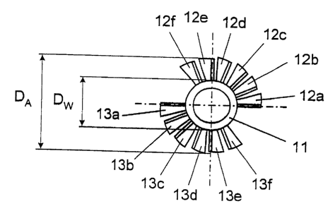
Fig. 2 shows a sectional view of a mixing device (1 ) according to the state
of the art. In
this mixing device (1), two intermeshing shafts (11, 14) are formed as hollow
shafts,
which rotate in same direction. Each shaft (11, 14) comprises two screws (12,
13, 15,
16), which continuously extend over the entire length of the shaft. The two
screws of a
shaft are offset by 180°.
Fig. 3 shows one of at least two shafts used according to the invention.
Instead of a
continuous screw, a plurality of individual blades (12a, 12b, 12c,...12m) are
arranged on
shaft (11 ) one after the other in a helical line. A first row of individual
blades (12a, 12b,
12c,...12m) is associated with a second row of individual blades (13a, 13b,
13c,...13m)
that is offset by 180° on the shaft. In this representation, each row
of blades is
composed of 12 individual blades. The term screw or worm like arrangement
embraces
any regular or irregular arrangement of the blades, which enables the blades
(12a
through 12m, 13a through 13m) to be arranged in a lined up manner on said
shaft (11 )
CA 02529581 2005-10-26
and which enables said shafts (11, 14) to move on rolling contact to each
other without
any problems. The number of blades can be varied depending on the reactor
length, the
diameter relations between shaft and blade and the blade curvatures, which are
related
thereto. The viscosity or the particle size of the media to be mixed also has
an
influence, since the mutual distance of the blades can influence the initial
mixing time.
As with threads, the blades can be arranged in one row or in several rows
Fig. 4 is a plan view of the left front of the shaft of fig. 3. For
simplifying matters,
respectively six blades (12a, 12b, 12c,...12f) and (13a, 13b, 13c,...l3f) of
one row of
blades are only represented here. The diameter of shaft (11 ) at the fixing
point of the
blades is denominated diameter Dw and the outer diameter of shaft (11 ) at the
blades is
denominated diameter DA.
Fig. 5 shows the enlarged cutout "A" of fig. 3 with the angles of incidence of
an
individual blade (12a). Angle a indicates the angle of incidence of the blade
on the
shaft. Angle a is associated with diameter Dw of fig. 4. Angle ~i is the angle
of incidence
of blade (12a) at the outermost diameter DA. Thus, it is possible to influence
the axial
speed of the media by means of different angles of incidence of the blades via
the cross
section of the mixing device. On condition that the outer diameter DA is
double as long
as diameter DW, and the angle of incidence remains constantly the same (a =
~3), the
axial speed of the media to be mixed at the outer diameter DA is double as
high as the
one at diameter Dw of shaft (11). If the angle of incidence ~i of the blade at
the outer
periphery becomes smaller than the angle of incidence a at the fixing point of
the blade,
the axial speed at the outer diameter DA decreases to about half the original
value. By
variation of the angles of incidence a and (3 in relation to the diameters Dw
and DA, the
axial speed of the particles can be evened out over the cross section of the
mixing
device, which results into a more narrow distribution of the retention time.
The axial flow
thus approaches the desired stop-type flow.
This becomes even more obvious in fig. 6. For simplification, it is again
assumed that
the outer diameter DA of shaft (11 ) at the blades is double as long as
diameter Dw of
shaft (11 ) at the fixing point of the blades ~ DA = 2Dw .
CA 02529581 2005-10-26
6
With DW = 1.0 m and a constant rotational speed of 20 revolutions per minute,
the
peripheral speed of the particles at the fixing point of the blades is VW =
1.05 m/s. This
is thus also the radial speed VWr = 1.05 m/s. With an angle of incidence a =
16° of the
blade at the fixing point on the shaft, an axial speed of the particles of VWa
= 0.3 m/s
results.
With DA = 2.0 m and the same rotational speed of 20 revolutions per minute,
the
peripheral speed of the particles at the outer diameter of the blades is VA =
2.09 m/s.
This is thus also the radial speed VA~ = 2.09 m/s. With an angle of incidence
~i = 8° of
the blade at the outer diameter DA of the shaft, the same axial speed of the
particles of
VAa = 0.3 mls results. The same axial speed of the particles over the cross
section of
the mixing device can, of course, also be realized with other diameter
relations and
other angles of incidence.