Note: Descriptions are shown in the official language in which they were submitted.
CA 02529853 2012-03-14
WO 2004/112623 PCT/DE2004/001243
Water jet device for separating a biological structure
Description
The invention relates to a water jet device.
Such water jet devicco arc used particularly in the field of
human iuealciii~ .
Sikh a water jet device is' described in Fr 0 551 920 B1. This
water jet dew? siuhstantial.ly comprises a pressure generator,
a cylinder piston unit and a separating device in tha farm of
a Specific operating hand piece. In the cylinder space of the
piston cylinder unit, a c.ax-LLiaye being filled with a sterile
separating liquid is inserted in a form-fit manner. This
cartridge, on tha nna hand, contacts the piston of the piston
cylinder unit, and is connected to the operating hand pier.e
via a pressure line, on the other hand. During operation, the
pressure fluid of laic pse~5ure generator loads the piston
cylinder unit and so the cartridge, and as a result of which
the separating liquid is discharged from the cartridge toward
the operating hand piece. The.rP, the separating liquid comes
uvt in the form of a fine jet of liquid. By separation of thp
separating lieluld circuit from the pre33urc liquid circuit and
by means of a special design of all iiisLrument components of
t.hA separating liquid circuit a continuous chain of sterility
is ensured.
CA 02529853 2005-12-16
2
WO 2004/112623 PCT/DE2004/001243
However, due to the limited filling volume of the cartridge it
Lu.Lned out that such a water jet device is not suited for
these cases of application which require a greater quantity of
separating liquid. All applications of plastic surgery, in
particular the liposuction are part of it.,Another
disadvantage is in that for specific cases of application, the
uniformly emerging jet of liquid has to be pulsed with an
auxiliary unit. This effort. is relatively high.
From US 6,216,573 Bl a water jet device has come out now which
docc not have these disadvantages. This water jet device
comprioco a higher oituated otorago container for the
separating liquid, a piston pump and an operating hand piece.
The higher situated storage container is`connected to the
piston pump via a soil pipe, wherein, a
pxessuxe line lead
from the piston pump to the operating hand piece. For this
purpose, the piston pump comprises a pump casing having the
piston cylinder unit and an.eccentric drive propelling the
piston of said piston cylinder unit wherein a membraneous
1 i q,ui d hl adder is inserted into the cylinder space of the
piston cylinder ,unit, and the residual cylinder space is
charged with a pressure liquid. Th.,- mamhranwc us liquid
bladder, ono the one hand, is connected to the storage
container via the soil pipe, and to the operating hand piece
via an opening check valvc and via the pressure line, on the
athtiu xzdz,a.
The membraneous liquid Lluddci is generally and alternately
pressurized with overpressure or SuLpiessure by the motion of
the piston such that the separating liquid in the storage
container is drawn in a pulsating manner and is subsequently
fe,i in a pulsating manner toward the operating hand piece.
However, this water jet device has disadvantages. Thus, the
piston cylinder unit does not generate any defined and sharp
CA 02529853 2005-12-16
3
WO 2004/112623 PCT/DE2004/001243
separating jet due to the separating jot being mainly
deLermined by the volume change of the liquid bladder, and
this volume change is not reproducible because the liquid
bladder is merely fixed by two liquid columns. The piston
cylinder unit is not efficient enough either- Primarily it has
to do with the fact that the direction of the liquid otrcam
dtEL'iviU.ly lUULL Olkz~ llc4uid bldddeL, dud Lite Ulie :Lioii or Lhe
pressure liquid stream emerging from the liquid bladder are
with opposite direction. This results in turning back of the
liquid flow within the liquid bladder and so in turbulences
and drop in pressure.
IL i5 disu ciisadv'antageous that there arc two separate liquid
circuits again which are to be separated from each other with
high effort due to the requirement of sterility. However, an
important di sadvantacj. i s in that- 1-J piston cylinder unit and
the eccentric drive are accommodated in a common pump casing
which because of that becomes largely and heavily constructing
and may only be used fixedly- This raises L.tie priue ur
manufacturing and strongly restricts the tunctional.range
since the volume of the 1i.gii d h1adde r ig merely designed for
a selected range of application. Adaptation of the piston
cylinder unit to different caaeo of application having a
greater need of separating liquid ib t1UL po~35i.ble clue Lo Llic
compactness of the pump casing, and the use of a greater
liquid hladder in the existing pump casing has to be ruled out
because the liquid bladder and the piston cylinder unit have.
to be well-matched to each other.
In US 5,310,609 A there is now described a water jet device
for removing thrombosis deposits which substantially comprises
a storage container having a separating i.i.gi.ii d, A driven
CA 02529853 2012-03-14
4
piston cylinder ,ini t fnr hiii 1 Hi ng-lip a .saparati ng jet, an
operating hand piece and suction means for drawing nff the
separated thrombosis deposits. On that occasion, the piston
cylinder unit io conncctcd to the storage container via a
suction line, and to the operating hand pioce via a pressure
lime and a distributor unit. Through the same distributor unit
these is alau provided a connection between the operating hand
piece cin(i Ll1C ~UuLiUli LU dlls.
or hygienic reasons, the piston cylinder unit is dis~;vsdk;] e,
and so being designed separably from all assemblies, whereas
all other assemblies are inseparably linked with each other.
There are some disadvantages. So, for hygienic reasons the
distributor unit and the operating hand piece have to be
.snhstitllted as well after any use which means that all the
other ass?mh1ie~ being hygienically not- so sensible such as
the suctior. mea.n.s then have t:o he simultaneously thrown away.
In addition, the compactness of the. water jet device results
in that it is only allowed to be used for GpArifir cases of
application. This rcetriot the functional range thereof
4
strongly. Then, for diffcrcnt cases of application a specific
wdle~ jet device has alway3 to be provided in its entire
compac;Liie56. This raises the price of the water jet device.
As a result, the invention is based on the development of a
water jet device according to type .ul. separating a biological
structure, whlcf is built up in a C Ut'clditt N wiLli LI e modular
design principle and which can be adapted to different cases
of application by means of substitution of individual
instruments.
CA 02529853 2005-12-16
T}P parti rni1 ar adzrantage of the novel. water jet device is in
that the piston cylinder unit is designed as an individual
assembly, and as a result become; indcpcndcntly from the
eccentric drive mcano. Thereby, it is possible for the piston
cylinder unit to be manufactured in a simple and cost
effective manner, and to assemble iL wiLi Llae appropriaLe
ptessULe dud auwLioi1 lilies and with the operating hand piece
as a set. As a result, the set can be designed for a
particular_ case of application, and can be substituted for
another set in case of a different application.
This opens a wide field of application for the water jet
device.
Then it is advantageous when the combination of the piston
cylinder unit having the eccentric drive means will be
designed as a plug-in coupling. This facilitates the action of
substitution.
The particular design of the piston cylinder unit is quite
suitable. Thus, in addition to the suction and pressure space
this piston cylinder unit coxtprises a parked position space in
which Lhe sealing element of the piston in the extended
position is submerging and releasing it. Because of that,.the
fundamental shape and as a result the sealing function remain
maintained over a long storage period which often equals to
several month3 and years. And co, the water jet device becomes
more reliably in operation.
CA 02529853 2005-12-16
6
WO 2004/112623 PCT/DE2004/001243
In addition, this parked position space offers the advantage
for the fixed membrane to have sufficient free space for Lhe
motions. This allows a sequence of motions of the membrane
without constraint during the piston motions, and as a result
prolonging the operating life of the membrane.
It is suitable when the parked position opacc or at lcaot the
transition from the suction and pressure space is designed
conically, so as to allow the sealing element to submerge in a
careful manner into the suction and pressure space. This
increases the operating life of the membrane either-
Tt is of particular advantage when t.hp c-y1inr1Pr rasing and the
pi stun of the pi stun ny1 i nri.r uni i- is, in cl;- of pl ast.ic, and
when the seal i nrg el emenh. of i-ha pi ston i riP~l rJnPrl a~ a
sealing lip machined on to the piston, and projecting. This
facilitates manufacturing in a considerable degree.
An advantageous design of the pressure intake on the cylinder
casing results in that a pressure tubule having projecting
press ribs and a press sleeve encircling the pressure tubule
are pressed into the cylinder casing. As a result, the
pressure line is pushed into the space between the press
sleeve and the pressure tubuie, and is radially pressed
together.
A simple installation of the pressure intake results from the
suction intake and pressure intake being situated radially
opposite to each another. Then, the pressure tubule can be
inserted and pressed together from inside into the cylinder
c dsilay via Llze suction inLake. The radially opposing
axrcttayetuetiL cr Lli su(jLiuii iliLake and pressure intake is also
Vr yiedL advantage such that the entering suction stream and
Llie, exiting pressure stream are directed in the same
direction. This avoids unnece33ary prcoourc drop loooco in the
flow, and e high energetic efficiency with it.
CA 02529853 2005-12-16
7
wo 2004/112623 PCT/DE2004/001243
The invention shall be explained in more detail according to
an embodiment in which:
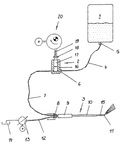
Fig. 1 shows a schematic .reprP. ni-.at'.i on of the water jet
device, and
Fig. 2 shows a piston pump of the water jet device.
According to Fig. 1, the water jeL device fui 5epaiating a
biological structure comprises a storage container 1 for the
separating liquid to be used, a piston cylinder unit 2 and an
operating hand piece 3. On the occasion, the storage container
1 and the piston cylinder unit 2 are connected to each other
via a suction line 4 wherein thA suct,ionlinP 4 is connected
to the storage container 1 via a first plug-in coupling .5, and
to the piston cylinder unit 2 via a second plug-in coupling 6_
In contrasL, Ltie piston cylinder unit 2 is connected to the
J
operating hand piece 3 vid d pressure line 7 whereas the
connection to the piston cylinder unit 2 is auuonaplis1xed by
means of a preterably permanent joint, and the connection Lu
the operating hand piece 3 is accomplished by means of a third
plug-in coupling 8.
The operating hand pi P.C'p. 3 in a well known manner comprises a
hand piece 9 and a pressure and siir.tA on pipe 10 . The pressure
and suction pipe 10 has an internal pressure tubule with a
ditic:llarging nozzle 11 situated at the end, which communicates
with Lhe pressure line 7 leading to the operating hand piece
3, and it has a suction pipe which sheathes the pressure
tubule torming a ring channel, and which i5 connected to a
receiving tank 14 via an exhaust line 12 and a driven exJ1dusL
pump 13. Furthermore, the suction pipe has radial exhaust
apert-.urec 15 being arranged in a circumferentially distributed
CA 02529853 2005-12-16
3
WO 2004/112623 PCT/DF_.20o4/00194.3
manner to r'PcQ!vQ the separated tissue particles and collected
separating liquid.
The piston cylinder unit 2 comprioc3 a cylinder casing 16 and
a piston 17 fitted with clearance in the cylinder casing 1G.
This piston 17 is connected. to the actuating cam follower; 19
of an eccentric drive means 20 via a plug-in coupliuy 16.
In Fig. 2, the piston cylinder unit=2 is illustrated in more
detail and shows again the cylinder casing lb and the piston
11 having its plug-in coupling lU tor the eccentric drive
means 20. The cylinder casinq 16 comprises a blind hole havinq
a cylindrical portion which is close to the obturated end of
the blind hole, and a conical portion which is in the area of
Ã'ho open end of the blind hole. On that occasion, the open end
of the hi i nci hnl P will hP r-1 c d by means of the nasi ncg cover
21 in a pressure-sealed manner. The piston which. penetrates
the cylinder cap 21 with a coupling shank 22, on the one hand,
and has a scaling lip 23, on the other hand, is inserted into
the blind hole of the cylindor casing 16. As a result, the
piston 17 with its sealing lip 23 and the blind hole of the
cylinder casing 16 with its cylindrical portion form a auction
cLiiU k)jJ 55uiC space 24, whereas an annular parked position
space 25 r'e5u1L5 L Lweeli Lhe ui_uL:umfe ence of the piston 17
and the conical portion of Life bllrnLI I1u1 . On L11sL uuuaoic u,
the length ratios between the piston 17 and the two pot Llolls
of the blind hole of the cylinder casing 16 are selected such
that the piston 1/ in its extended final position is in
abutment with the casing cover 21, and the sealing lip 23 is
then takinq up a position in the transition area from the
cylindrical portion to the conical portion of the blind hole.
In,this position, the sealing lip 23 is some strain-free,
hnwPver, still ensuring sufficient proofness between the
CA 02529853 2005-12-16
9
WO 2004/112623 PCT/DE2004/001243
auction and pressure space 24 as well as the pdrAeU posiLioil
space 25. A membrane 26 i5 arr'dnyed between the piston 17 and
the cylinder casing 16 which, on the one hand, is clamped
between the cylinder casing 16 and the casing cover 21, and on
the other hand, is fastened into an annular groove of the
piston 17. This membrane 26 has such room to move then during
cooperating with the parked position space 25 snnch that a
sufficient stroke of the piston 17 is ensured without
stoppage- The casing cover 21 is further equipped with an air
compensation hole 27 which connects the volume varying air
opaco botwccn the membrane 2G and the casing cover 21 with the
atmosphere.
The ~uc;LIQLI ailc~ pressure spa(;e 24, on .Lhe one hand, has a
radial suction intake which is connected to the suction line 4
leading to the storage container 1 via the second plug-in
couplinq 6. A check valve 28 opening in the suction direction
is inserted into this suction intake. Opposite the suction
intakes thRrA is a radial pressure intake 29. This pressure
intake 2A <-.cmpri sPs a prAS9i rA t.nhul e 30 which is pressed from
inside into the cylinder casing 16 through the suction i.ntak.,
and is equipped with external press ribs on the projecting end
thereof. A prcoa olccvc 31 which ],.ccpo an annular clearanco
toward the pressure tubule 30 free io externally precocd
through this pressure tubule 30 into the cylinder casing 16.
The pressure litre 7 leadiiiy Lv Lfie operdLitiy l~dr~d piece 3 is
inserted into this annular clearance and pressed LoyeLtiet wiLli
the pressure tubule 30 by means of force acting on the press
sleeve 31.
In,operation, the eccentric drive means 20 starts to move the
pisf.nn 17 of the piston cylinder unit 2 in a pendulous motion
CA 02529853 2005-12-16
WO 2004/112623 PCT/DE2004/001243
wherein the piston 17 is alternately retracting and extending.
While extending the piston 17, the suction-and prescurc space
24 iiic;reases such Lhat a diminished pressure is generated
which opens the check valve 28 in the suction line 4 died ye-L-6
the separating liquid to suck from the storage container 1_
This intake operation is supported in that the storage
container is placed in a higher si.t,.u.atpd pnsi t.i on, and thus
use of the potential proaeure of the separating liquid
situated in the storage container 1 will be made. While
retracting the piston 17, the suuUiuii died pressure space 24
decreases, and overpressure is generated which closes the
check valve 28 in the suction line 4 and qets the separating
liquid in thR Rnnt,.i or and pressure space 24 to feed into the
pressure line 7 via the pressure tiihiile in- From there, the
separating liquid reaches to the operating hand piece 3 in a
well known manner where it emerges ao a concentrated or spread
separating jet from the discharge nozzle 11. Tile elue.cged
separating liquid and the split Ott tissue particles are drawn
off si rmi1 t.aneously effected by the exhaust pump 1:3 and are
deposited into a .. P.C!P.ivirg tank 14.