Note: Descriptions are shown in the official language in which they were submitted.
CA 02529932 2011-09-13
SECURE CONDUIT (PATHWAY) SYSTEM FOR TELECOMMUNICATIONS
AND COMMUNICATIONS TRANSMISSION EQUIPMENT, ENVIRONMENTAL
ANALYSIS EQUIPMENT, COMPUTER EQUIPMENT AND THE LIKE
BACKGROUND OF THE INVENTION
Field of Invention:
The invention relates generally to conduits, raceways and similar devices for
routing signalling or transmission apparatus such as cables, tubing and wires
(including
those composed of either metal or optical fiber) between locations. More
particularly it
relates to such devices which must be used for signalling or transmission in a
highly
secure environment.
Background Information:
In many industries, research facilities and governmental and military
facilities
there is a need for secure routing of signaling and transmission means such as
computer, power, communication and similar cables and wires and fluid
conveyance
tubing, e.g., gas and liquid pneumatic and hydraulic lines. (For brevity
herein such
signalling and transmission means will often be exemplified as and referred to
collectively as "cable", "cables" or "cabling" unless the context indicates
otherwise or
specific types of such means are mentioned. It will be recognized, however,
that such
collective terminology is used for convenience only and is not intended to be
limiting.)
Further, the terms "conduit" and "conduit system" may be considered synonymous
unless the context indicates otherwise.) Unauthorized access to such cables
must be
prevented or at least made extremely difficult while yet easy to detect.
Conduits for
routing of such cables must be protected from intrusion by penetration or
removal of
CA 02529932 2005-12-20
WO 2005/002015 PCT/US2004/020357
-2-
access covers or sections of conduit, and also must provide a suitable degree
of
physical protection for the transmission devices within the conduit from
environmental
hazards, weather and climate excesses and accident or attack. However, such
protection must not be so cumbersome that authorized access for removal,
repair or
insertion of the cables within the conduit is made excessively difficult.
Typical uses for the present secure conduit invention will be for computer
networks, communication systems, equipment control systems, remote sensing
systems and the like. Specific principal uses which may be illustrated as
examples are
as conduits for telecommunications cables, computer cables, power transmission
cables (especially for power to critical operational equipment or facilities)
and
environmental gas sampler tubing or piping. Users may be companies, research
organizations, military units and governmental organizations and agencies.
Facilities
where secure conduits are desirable include office and laboratory buildings;
military
camps and bases; ships, dockyards or other marine facilities; airports;
prisons; chemical
plants and petroleum refineries; factories; banks, exchanges and other
financial
institutions; and power, gas and water utilities.
In the past, there have been numerous cable and other routing systems, such as
those used to route computer, electric power and communications cables and
wires to
and within offices, especially within a building. A particularly successful
example of
such a system is that described and claimed in U.S. Patent No. 5,831,211,
owned by
the assignee of the present invention and patent application, Holocom Networks
of
Carlsbad, California, and commercially available underthe trademark
TOPRUNNERO.
A principal limitation of such systems, however, is that they are not secure
from
intrusion and cannot be made secure without extensive modification. Such
modification
is impractical in most cases, since the intent of their designers and their
users has been
to have them readily accessible to facilitate frequent reconfiguration.
Therefore while
such non-secure systems do provide functions similar to those of the system of
the
present invention, i.e., routing of cables, their physical structures and
security
capabilities are entirely different.
CA 02529932 2011-09-13
It would therefore be of significant value to have a secure conduit system
which
would provide security against unauthorized access to cables routed through
the
system, while at the same time permitting simple and easy access to those
cables
within the system to authorized persons.
SUMMARY OF THE INVENTION
According to an aspect of the present invention there is provided an apparatus
for secure routing of a signalling or transmission means which comprises:
a first open-sided open-ended elongated channel member through which said
means is routed;
a first cover for closure of an open side of said first channel member; said
first
channel member and said first cover in combination forming a hollow first
conduit
section;
a locking device to lock said first cover to said first channel member, said
locking device being releasable only from within said first channel member;
and
release means for releasing said locking device and accessible though an
open end of said first channel member;
whereby said hollow first conduit section can be disassembled only by release
of said locking device by access through an open end of said conduit section.
Normally- there will be plurality of channel members aligned end-to-end, each
with its own cover. For most of the channel members, the covers will be held
on by
simple locking tabs which engage projections or ribs within the channel
members.
After assembly of the latter cover/channel pairs, the remaining cover and
channel
member will be assembled with the locking device to secure the entire length
of the
conduit. The conduit preferably terminates at its ends in secure enclosures
which
limit access to the interior of the conduit to only that which can be gained
through the
enclosures. Other secure enclosures may be spaced along the length of the
conduit.
CA 02529932 2011-09-13
- 3a -
T-, Y-, L- and X-shaped and other curved, bent, or multibranched raceway/cover
pairs can be included in the conduit structure to form branches which allow
conduit
directional changes, junctions and multiple conduit routes. In such cases each
conduit
branch should terminate in a separate secure enclosure, and normally a
cover/channel
pair with a locking device will be included in each branch, unless the branch
is quite
short, such that it can be secured by abutting the main secured portion of the
conduit.
CA 02529932 2005-12-20
WO 2005/002015 PCT/US2004/020357
-4-
The signalling or transmission means of significance in this invention
includes,
but is not limited to, computer, power, communication and similar cables and
wires and
fluid conveyance tubing, e.g., gas and liquid pneumatic and hydraulic lines.
Within the
secure conduit of this invention any one or more of such means may be routed,
the
number being limited primarily by the physical size of the conduit and by the
sharpness
of any turns in the conduit. Where a conduit has multiple branches, individual
cables
may follow different paths through the conduit system, such that different
numbers of
cables may be present in different branches of the system.
The locking device which permits securing of the cover to the conduit may be
secured within the conduit in a variety of manners, such as by use of spring-
urged pins
engaging projecting ribs on the interior walls of the conduit or by use of
bolts which
allow clamping of the locking device to both the top of the conduit and to the
interior
ribs.
Details of the invention and further descriptions will be found below.
BRIEF DESCRIPTION OF THE DRAWINGS
Figure 1 is a side view of a typical conduit assembly mounted on a wall of
other
supporting surface;
Figure 2 is a perspective view of a flange connector;
Figure 3 is an enlarged sectional view taken on line 3-3 of Figure 1;
Figure 4 is a perspective view from above of a locking unit;
Figure 5 is a perspective view from below of the locking unit of Figure 4;
Figure 6 is a perspective view of a section of a raceway;
CA 02529932 2005-12-20
WO 2005/002015 PCT/US2004/020357
-5-
Figure 7 is a perspective view of a section of a top cover;
Figure 8 is a perspective view of a lock connector;
Figure 9 is an end view of the lock connector of Figure 8 with the locking tab
secured in place;
Figure 10 is a perspective view of a snap-in connector;
Figure 11 is an end view of the connector or Figure 10 with the snap spring
secured in place;
Figure 12 is an enlarged sectional view taken on line 12-12 of Figure 6
showing
the initial insertion of a locking unit;
Figure 13 is a view similar to Figure 12 showing the locking unit secured in
place;
Figure 14 is an enlarged sectional view taken on line 14-14 of Figure 3;
Figure 15 is a view similar to Figure 13 illustrating an alternative
embodiment;
Figure 16 is an enlarged sectional view taken on line 16-16 of Figure 1;
Figure 17 is an enlarged sectional view taken on line 17-17 of Figure 16;
Figure 18 is a perspective view of a corner raceway component;
Figure 19 is a perspective view from below of a corner top cover;
Figure 20 is a top view of a T-shaped junction unit;
CA 02529932 2005-12-20
WO 2005/002015 PCT/US2004/020357
-6-
Figure 21 is a schematic view from above of a mechanized system for locking
and unlocking the locking unit;
Figure 22 is a perspective view from above of yet another alternative version
of
the locking unit of Figure 4 illustrating a different structure for securing
the locking unit in
place.;
Figure 23 is a perspective view from above of an alternative version of the
locking unit of Figure 4;
Figure 24 is a perspective view of above of another alternative version of the
locking unit of Figure 4;
Figures 25 and 26 are respectively perspective views from below of the locking
unit of Figure 24 in an unlocked and locked configuration, illustrating
locking and
unlocking by spring pins and a U-shaped spring release;
Figures 27, 28 and 29 are perspective separated views of the two halves of
respectively a T-shaped locking junction unit, an X-shaped locking junction
unit and an
L-shaped locking corner unit;
Figure 30 is a plan view from below of the interior of an L-shaped bend unit,
similar to the L-shaped corner unit of Figure 29;
Figures 31 and 32 are oblique views of one end of alternative embodiment of
raceways of Figure 6 formed respectively from aluminum and steel
Figures 33 and 34 are, respectively, an oblique and an exploded oblique view
of
an alternative embodiment to the release mechanism of Figures 25 and 26;
CA 02529932 2005-12-20
WO 2005/002015 PCT/US2004/020357
-7-
Figure 34 is an oblique view from below of a top cover illustrating an
alternative
means of locking the top cover in place;
Figure 36 is an end view of an assembled raceway, top cover and locking
mechanism of Figures 34-36, with the locking rod removed for clarity;
Figures 37 and 38 are, respectively, an oblique and an exploded oblique view
of
an alternative lanyard embodiment to the spring release mechanism of Figures
29 and
30 for corner (L-shaped) and angled sections;
Figures 39 and 40 are respectively an oblique and top view (with the top cover
removed) of a large radius T-junction section of conduit, illustrating a
release
mechanism equivalent to that of Figures 37 and 38;
Figure 41 is an oblique view similar to that of Figure 39 but illustrating an
embodiment where locking release is by spring mechanism rather than by lanyard
release; and
Figure 42 is an elevation view, partially in cross-section and cut away,
illustrating
a structure for connection between two secure systems through a barrier wall.
DETAILED DESCRIPTION AND PREFERRED EMBODIMENTS
For the purposes of this invention, the terms "secure", "secure conduit",
"secure
conduit system", "secure enclosure" and the like are intended to include those
systems
which meet the requirements of "Protective Distribution Systems (PDS)" as
defined by
the National Security Telecommunications and Information Systems Security
Secretariat of the National Security Agency in Instruction No. 7003 (NSTISSI
7003:
issued 13 December 1996), the content of which is incorporated herein by
reference. In
addition to those secure conduit systems which are "secure" within the meaning
of the
PDS requirement, the present invention may also be used for secure conduit
systems
where the degree of security is not within the specific PDS standard. Such
other
CA 02529932 2005-12-20
WO 2005/002015 PCT/US2004/020357
-8-
conduit systems may include various non-governmental and/or commercial systems
to
which NSTISSI 7003 may not be applicable or where application is voluntary.
It will also be recognized that security of a conduit system is often a
function of
both the system's resistance to penetration or entry and the ease of an
observer's being
readily able to tell that penetration or entry has been attempted or
accomplished. Thus
as will be described the conduits of the present invention are commonly
installed with
stand-offs or other means to isolate the conduits from contact with adjacent
surfaces,
such that an observed can by sight or touch readily examine all exterior sides
of conduit
components to detect any attempt at penetration of or entry into the system.
Thus
where inspection of a system is frequent or the sections of the system are
readily in
view of observers, such that attempts at penetration or entry will be easily
seen, the
conduit components themselves for such sections may be formed of materials
which
are themselves less resistant to penetration that would be called for in
sections of the
conduit where inspection is less frequent or more difficult to accomplish.
The invention described and claimed herein is a secure conduit system through
which electrical, electronic or optical fiber cables, pneumatic tubing,
hydraulic tubing or
other elongated wiring, cabling or tubing can be routed. The conduit system
can be
connected at its various ends to secure enclosures which allow for secure
controlled
access to the cabling inside the conduit system. Typical uses will be for
computer
networks, communication systems, power transmission, equipment control
systems,
remote sensing systems and the like. Principal uses which may be illustrated
as
examples in electrical, electronic and telecommunications fields include
secure routing
of power cables, computer cables and communications cables for networked
computer
systems and wired telecommunications systems. Locations may be within, between
or
outside buildings. The secure conduit system will also be of importance even
with
wireless communications systems, such as for security of landline cabling from
the
generating or receiving equipment to the sending/receiving antennas.
Another example of potential users' systems is a system for remote
environmental air, gas or liquid sampling and analysis. In this type of
system, a
CA 02529932 2005-12-20
WO 2005/002015 PCT/US2004/020357
-9-
fluid-tight tube, hose or pipe is run from a storage or analysis location to a
remote
sampling site where the pipe terminates in an open liquid-, air- or gas-
sampling device.
Periodically or continually samples of the environment at the sampler point
are taken,
and then transported back through the pipe to a collection system for analysis
or directly
to an analysis system. Such secured pipe is desired when the liquid, gas or
air in the
pipe cannot be leaked to the outside or accessed by unauthorized persons or in
an
unauthorized manner. Such unauthorized access is of particular concern when
the
liquid, gas or air being sampled is itself flammable, toxic or otherwise
dangerous, or
when it may be contaminated with or otherwise carry or entrain flammable,
toxic or
otherwise dangerous components.
It is not intended that the secure conduit itself normally be air-, liquid- or
gas-tight,
although its closed configuration is such that it can be exposed to inclement
environments and will to some extent resist infiltration of rain, snowmelt,
blown dust and
similar common environmental elements. Should greater environmental protection
be
desired, it is contemplated that the cabling can be encased in a protective
sleeve or
similar device prior to being installed within the conduit, or alternatively
the conduit itself,
after insertion of the cables can be encased in such a protective covering. It
will be
recognized that reconfiguring of the conduit contents will thereafter normally
necessitate
removal of some or all of the protective covering.
It will be understood that reference to an embodiment as "alternative" is
intended
to indicate only that the present invention includes a number of variations of
the various
embodiments as to structure, materials of construction, number and types of
conduit
components, and the like. All are considered to be substantially equivalent in
overall
performance. A user of the invention can readily select the specific
combinations of
components, materials, etc. which are best suited for the particular location,
environment and specified security requirements for the particular system
which he or
she needs. Numerous examples will be referred to below.
The invention is best understood by reference to the Figures of the drawings.
CA 02529932 2005-12-20
WO 2005/002015 PCT/US2004/020357
-10-
Figure 1 shows the components of the secure conduit system 2 in a very
simplified
installation and a wall 4. Installations will commonly be mounted on walls,
ceilings,
space dividers, bulkheads, building structural members such as columns,
rafters, studs
and joists, and other similar supports. They may also span short unsupported
spaces
(usually not more than 3-10 ft [about 1-3m]) such as running across spaced-
apart joists
or studs. The raceway may be surface mounted, but for the most security,
however,
and as required for PDS installations, most or all of the secure conduit will
not be
surface mounted, but rather will be mounted spaced apart from the surface
overwhich
it runs, so stand-offs are needed along the conduit to maintain it in
position. This
requirement is to insure that observers of the conduit can detect any attempts
to
penetrate the conduit from its back side, by being able to see any suspicious
hole in the
surface to which it is mounted or any suspicious device bridging the gap
between the
surface and the conduit. Over the length of a conduit run, different means of
attachment, stand-off and support may be used at different locations.
Prior to installation, one first determines the locations of the various
secure
enclosures 6 needed along the secure conduit 2 and the desired route of the
conduit
(including branches thereof) to reach those enclosures. It is not necessary
that the
route selected be the shortest possible. As noted, there are a number of
different uses
for the secure conduit which are anticipated to result in different numbers of
secure
enclosures along the route, with different spacings between adjacent
enclosures.
Secure enclosures 6 have been produced and sold commercially by the assignee
of this
patent application and are also the subject of copending U.S. utility patent
application
Ser. No. 10/112,353, also assigned to the assignee of this application.
Essentially each
such secure enclosures 6 incorporates a box-like structure which houses a
connection
to apparatus of a secure signalling or transmission system 2 such as a
computer
network, communications network or environmental analysis system. To attach to
or
gain access to the secure system 2, a user must have a device (e.g., a
computer)
external to the enclosure but which can be connected to the system 2. The
enclosure 6
is normally closed by a penetration-resistant door, which if desired may have
a back
flange to further enhance penetration resistance and which is locked by a
secure lock.
CA 02529932 2005-12-20
WO 2005/002015 PCT/US2004/020357
-11-
(Where the system is one which meets the PDS requirements, the lock itself
will meet
corresponding governmental requirements.) An authorized user will have a key
or
combination to the lock and can open the door and access a connection device
on the
secure system 2 apparatus within the enclosure. The user then makes the
connection
with his/her device and proceeds to do whatever is desired during access to
the secure
system. For instance, a computer user could access a secure database or give
operating commands to a piece of equipment which is operated via the secure
system
or a chemist could take samples of the fluid passing through an environmental
sampling
tube. Security of the enclosure is assured since the user must keep the door
open
while having access, so an observer can see the user at work. Normally only a
single
connection is provided inside each enclosure, so only a single individual can
access the
system at a time through the enclosure. Further, if the user terminates
his/her use of
the system but does not close the enclosure after use, that also is observable
since the
door can be seen to be open and the identity of the user as the person who
last
accessed the enclosure will be known. While Figure 1 shows secure enclosures 6
at
each end of the conduit 2, it will be recognized that additional secure
enclosures may
be positioned at points along the length of the conduit 2, such that access
may be had
to intermediate sections of the contained cables. Thus, for instance, multiple
computer
access enclosures may be present on a single computer network cable so that
multiple
computer users can access the computer network, each through his or her
individual
access enclosure.
It is also possible to interconnect two physically separate secure systems of
this
invention. Figure 42 illustrates such a connection through two secure
enclosures 6 and
6' mounted on opposite sides of a barrier wall 230. Corresponding holes 232
and 232'
are drilled through the back of each enclosure 6, 6' and through the wall 230
and a
short strong pipe or elongated nipple 234, threaded on both ends, is passed
through the
holes and extended into the interior of each enclosure 6, 6', where it is
secured by
conventional nuts and washers 236, 236' covering the annular portions of the
holes
232, 232, so that external access to the pipe 234 is prevented. Wires, cables,
and
pneumatic conduits from a secure system 2 of this invention can then be routed
through
CA 02529932 2005-12-20
WO 2005/002015 PCT/US2004/020357
-12-
the pipe 234 to a second secure system 2' of this invention without
compromising the
integrity and security of either system.
The secure conduit system 2 connects to a secure enclosure 6 by means of a
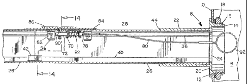
flange connector 8, as shown in Figures 2 and 3. The wall 10 of enclosure 6
has an
aperture 12 (usually circular) through which the circular end extension 14 of
the flange
connector 8 is inserted. Extension 14 has external threads 16 which are
disposed
within the enclosure 6 upon insertion and the connector 8 is secured to the
enclosure
wall 10 by threading circular nut 18 onto threads 16 until flange 20 of
connector 8 abuts
the exterior side of wall 10. Extending from flange 20 is connector tube 22
which is
hollow with a cross-section (usually square or rectangular) which corresponds
similar to
the cross-section of the raceway 26 and cover 28. An aperture 24 in flange 20
provides
passage for cables from within the enclosure 6 into the connector tube 22 and
thus into
the conduit system.
A principal component of the system 2 is at least one, and usually many,
raceways 26. A raceway 26 can be any convenient length. It is convenient to
provide
stocks of raceway 26 in several standard lengths, for example 1, 3, 6 and 10
feet (or
metric counterparts of 30 cm and 1, 2 and 3 m). These can be cut to shorter
lengths as
needed and joined to make longer lengths. Covering the raceways over most of
their
length are at least one (and also usually many) top covers 28. As best shown
in
Figures 3, 6, 31 and 32, a raceway 26 is an elongated channel member having a
generally U-shaped cross-section with an open top 30 and suitable for the
routing of
cables, wires, tubing and the like. (For purposes of this invention the word
"raceway"
includes all suitable elongated channel members, regardless of whether they
may be
referred to by other names in specific industries.) The specific U-shaped
cross-section
is not critical, as long as it can securely interfit with a corresponding top
cover 28. The
particular U-shaped cross-section will in many cases be dependent on the type
of
material from which the raceway 26 (and top cover 28) is made and how it is
manufactured. For instance, aluminum raceways may be formed by extrusion,
which
allows for rounded configurations and internal ribs (see Figures 3, 6 and 31)
while steel
CA 02529932 2005-12-20
WO 2005/002015 PCT/US2004/020357
-13-
raceways commonly are formed by bending which results in more straight-sided
and
sharper-edged embodiments (see Figure 32). In the embodiment of Figures 3 and
6,
the side walls 32 curve over inwardly at the top to form protruding
longitudinal flanges
34. Positioned on the interior of the raceway 26 and disposed parallel to
flanges 34 are
a pair of longitudinal ribs 36. In the Figure 31 embodiment, the top potion
34' of flanges
34 is flattened with an inwardly folded end portion 34", and the function of
the ribs 36 is
performed by the downwardly facing ends 36' of the folded end 34", while in
the Figure
32 embodiment the structure is generally V-shaped with top portion 34' being
rounded
and the end portions 43" slope inwardly. The bottom of the raceway 26 is
usually flat as
shown in Figures 31 and 32, but may be stepped as shown at 40 to accommodate a
linking plate 42 which connects two raceways abutting at their ends (Figure
3). One half
of a gap bridge 42 is secured to the inside of the bottom of the raceway 26 as
by
adhesive bonding or spot welding, and then the other half is similarly secured
to the
abutting raceway 26 to form a firm connection between the two raceways. For
most of
the raceway elements 26, a closed top cover 28 having a complementary U-shaped
cross section and no apertures (see Figure 7) is used to close the open top 30
of the
raceway 26 once the cabling has been inserted. The closed top cover 28 has
secured
on the inside thereof (as by spot welding) a locking tab 38, which interfits
with the ribs
36 and locks the top cover 28 in place.
To start assembly of a secure conduit system 2 a flange connector 8 is first
inserted into a secure enclosure 6 and fastened tightly as described above.
One end of
a first raceway 26 is inserted fully into the connector tube 22, butting up
against the
portion of flange 20 which surrounds aperture 24. In the embodiment
illustrated in
Figure 3, a top cover 28 is then fitted over the raceway 26. This top cover 28
will have
an aperture 88 in it as illustrated in Figure 8, for cooperation with the
locking device 52
as will be described below. Connector tube 22 will be sized to accommodate
both
raceway 26 and top cover 28, so that the leading end of top cover 28 will have
its end
also abut flange 22 and the entire combination of the raceway 26 and the top
cover 28
fill the interior of connector tube 22. At least for the first section of the
conduit, the top
cover 28 is preferably longer than the raceway 26 so that when the second
raceway 26
CA 02529932 2005-12-20
WO 2005/002015 PCT/US2004/020357
-14-
is attached to the first raceway 26, the first top cover 28 will extend over
the exposed
end of the first raceway 26 for a short distance to cover the joint between
the two
raceway elements. A gap bridge 42 will join the two raceways. Thereafter the
second
raceway 26 is capped with a top cover 28 which does not have an aperture 88. A
locking tab 38 may be positioned in the second top cover 28, as shown in
Figures 10
and 11, to engage the ribs 36 in the second raceway 26 to secure the second
top cover
28. Alternatively, if desired the structure of Figures 10 and 11 may be a
supplemental
cover 85 which can be slip fitted to overlay two abutting top covers 28 and
28' and
extend into abutting raceways 26 and 26' to lock the raceways and top covers
together
through engagement of the tab 38 and thus block penetration or separation of
the
abutment joint 87, as illustrated in Figures 16 and 17. It will be seen that
conduits of
any desired length can be constructed in this manner by sequential assembly of
additional raceways 26 and top covers 28, as desired, either joined directly
by tabs 38
or indirectly by supplemental covers 85.
L-shaped corner or elbow raceways 46 (Figure 18) their top covers 48 (Figure
19) and corresponding T-, Y- and X-shaped or other multi-armed branching
junction
raceway units and their corresponding top covers (generally indicated at 50;
Figure 20)
may be incorporated as needed to construct the desired overall system
configuration.
Where larger diameter wires or cables are to be routed within the system 2 or
where
there are a large number of wires or cables within the conduit 2, it will be
desirable to
use broadened configurations of the L-, T-, X- and Y-shaped junction units
such as
illustrated in Figures 39, 40 and 41 at 51. The broadened configurations allow
for larger
radius turns of the wires or cables and thus prevent kinking at turns. Some
corners and
other units may have the raceways and covers secured together by the locking
mechanisms described herein which incorporate internal and external elements
as
illustrated, e.g., in Figures 3 and 16. However, alternative configurations of
such units
with internal locking mechanisms are illustrated in Figures 27-30, 38 and 40.
In these
alternative configurations the raceway 26 has secured to the middle portion
thereto (as
by spot welding or strong adhesive) an upwardly extending bar 210 terminated
by a
barrel 212 disposed parallel to the inner top surface of the top cover 28. The
inner top
CA 02529932 2005-12-20
WO 2005/002015 PCT/US2004/020357
-15-
surface of the cover 28 has a corresponding latching member 214 which is
configured
as one half of a hinge, with knuckles 216 serving as guides for a sliding pin
218 (similar
to a hinge pin) with a hooked end 220 to allow for manipulation of the pin
218. In one
mode of operation when the raceway 26 and the cover 28 are interfitted, the
barrel 212
fits between two of the knuckles 216a and 216b with their respective axes
aligned, and
the pin 218 can be manually moved from within the interior of the interfitted
raceway/coverto a position where it is extended through the barrel 212 and at
least the
knuckles 216a and 216b in the manner of a hinge pin to lock the raceway 26 and
the
cover 28 together. While the T-, Y- and X-configured units can operate with
only one
bar 210/member 214 pair, the L-shaped corners or bends (elbows) will normally
require
two pairs, one in each leg of the L, unless the L is very shallow (i.e., the
bend or elbow
encompasses only a small angle). One can optionally put additional pairs in
two or
more arms of the T-, Y- and X-shaped units to enhance their resistance to
unauthorized
access. One may also support the pin 218 within the barrel 212 and have it
slide into
one or more of the knuckles 216 as illustrated in Figures 29 and 30. Other
convenient
configurations will be evident to those skilled in the art depending on the
specific
alignments of adjacent parts of the conduit bend, elbow, junction, etc. It
will also be
evident that once locked together in this manner, the raceway and cover can
only be
unlocked for separation from within the conduit, thus enhancing security and
prevention
of unauthorized access for the present system.
The system requires that at least one location a closed top cover will not be
used. Rather at this location a locking top cover (described below) will be
inserted once
the insertion of the cabling is completed and the closed top covers have been
placed.
In the preferred assembly procedure, at least for a portion of the system the
raceways
26 are first placed, including any corner or junction raceways in that
portion. Preferably
this section will be one which connects to a secure enclosure. The cabling is
then laid
into the raceways 26 through the openings 30 in their tops and the ends of the
cabled
passed into the interior of the enclosure. This installation of cabling by
simply laying
them in the raceways will be recognized to be much easier than having to
thread or fish
the cables through closed conduits. It may also be desired to lay the cabling
throughout
CA 02529932 2005-12-20
WO 2005/002015 PCT/US2004/020357
-16-
the entire conduit system at this time, instead of laying the cabling only for
one portion
of the system at a time, particularly if the system is fairly short (as for
instance within a
single room, a suite of rooms or a small building). Once the cables are
placed, the top
covers 28 can be installed, awaiting the installation of the locking
mechanisms to be
described below. Where there may be prior non-secure raceways of different
cross-section used in the system, one can use raceway covers with modified
snap-in
connectors configured to connect to the upper parts of those raceways and
provide the
needed security.
A critical element of the present invention is the securing locking mechanism
used to maintain the integrity of the conduit system while permitting its
simple and easy
unlocking and disassembly when desired, while yet insuring that the locking
system
cannot be unlocked or disabled by unauthorized means. This is accomplished by
means of locking plate assemblies inserted at the gaps in the top cover
installations
along the conduit. The top cover mechanism and its installation and operation
is best
illustrated in Figures 3-5, 8-9 and 12-14. (The embodiment illustrated is
typical when
the components are made of aluminum; Figure 15 parallels figure 13 to briefly
illustrate
the typical shape differences when the components are made of steel. The minor
differences imparted by different materials of construction are discussed
further
elsewhere herein.) One embodiment of the locking device 52 is shown from above
and
below in Figures 4 and 5, respectively. (Other embodiments will be exemplified
below.)
It comprises a base plate 54 which has a lateral width W slightly greater than
the width
of the opening 30 in the raceway 26. The plate 54 also has an aperture 68 and
guides
70 (conveniently formed by bending inwardly two tabs formed by cutting
aperture 66) in
which a longitudinally extending rod 72 is mounted through holes 76. Aperture
68 is
positioned such that retracting rod 72 clears its distal end 84 from being
beneath
aperture 68. Rod 72 has a flange 74 serving as a stop and a hole 78 near one
end to
which is attached a pull wire 80. A compression spring 82 surrounds the rod 72
and its
end distal from the hole 78 is attached to the rod 72. The spring 82 should be
of a
strength such that when released from compression it readily urges the rod 72
into a
locked position as described below, but not so strong that an excessive pull
on pull wire
CA 02529932 2005-12-20
WO 2005/002015 PCT/US2004/020357
-17-
80 must be used to retract it and release locking top cover 84 when access to
the
interior of the conduit system is desired. Depending from the corners of the
plate 54
are U-shaped support brackets 56 with apertures 58 therethrough to guide and
support
locking pins 60. Wedged between the pair of support brackets 56 at each end of
the
plate 54 is a spring metal strip 62, preferably made of spring steel. Prior to
insertion
into the conduit, the strips 62 are compressed inwardly as shown in Figure 12
and held
in that position by pliers handled by the installer. The strips 62 are
positioned inwardly
of and in contact with flanges 64 on the pins 60. (Other embodiments of
securing
means will be exemplified below.)
The assembly procedure then continues with the installer lowering locking
device 52 into an opening 30 in the space left between two closed top covers
30 (Figure
12) until the base plate 54 rests on the top flanges 34 of the raceway (Figure
13). The
holes 58 in the brackets 56 are now disposed below the ribs 36. The installer
then
releases the spring metal strips 62 which spring outward in contact with the
pin flanges
64, thus moving the pins 60 outwardly and under the ribs 36, thus securing the
locking
device 52 in place. In each system at least one (and usually most or all) pull
wire 80
must be long enough so that it extends to and through aperture 24 in the side
of
enclosure 6, where it terminates in pull ring 92. Only pull wires 80 which
terminate
inside a secure enclosure 6 can be operated to initiate opening the system.
Then a
locking top cover 84 (Figure 8) is placed over the opening 30 and the locking
device 52,
so that the ends of the locking top cover 84 overlap onto the ends of the two
adjacent
closed top covers 28 as shown in Figure 3, so that the entire length of
openings 30 in
the raceways 26 is now covered. The locking top cover 84 is placed so that its
aperture
88 is aligned with aperture 68 in base plate 54, rod 72 is retracted by an
installer pulling
on pull ring 92 from within the secure enclosure 6, and a T-shaped locking
bracket 86 is
inserted through apertures 68 and 88 so that the leg of the bracket 86 with
hole 90
projects into the interior of the raceway 26 and hole 90 is aligned with the
distal end 74
of rod 72 (Figure 3). The pull ring 92 is then released and, impelled by
compression
spring 82, rod 72 is urged forward and its distal end 74 passes through hole
90 in
bracket 86, thus locking bracket 86 from upward movement and securing locking
top
CA 02529932 2005-12-20
WO 2005/002015 PCT/US2004/020357
-18-
cover 84 in place. All components of the secure conduit system 2 are now
interlocked
into position with each other and none can be moved or removed until rod 82 is
again
retracted from hole 90 in bracket 86 by manipulation of the pull ring 92 from
within the
secure enclosure 6. With all of the locking plate assemblies in place and
their covers
locked to them, the conduit assembly is complete.
Alternative structures are contemplated for the locking device 52 and for
manipulation of the locking and unlocking mechanism. Figure 21 illustrates
mechanized
variations of the pull wire 80 and manual pull ring 92. The housing 182 is
contemplated
to contain a conventional mechanical or electromechanical actuator, (not
shown) such
as a servo mechanism, that will reciprocate a linkage 180 which causes the rod
72 to
engage or disengage the bracket 86 as described above. Alternatively within
the
housing 182 could be a pneumatic or hydraulic actuator cooperating with
linkage 180 (in
this case in the form of a fluid-filled tube, which acts through a pressure-to-
mechanical
coupler 184 to engage or disengage the bracket 86 as described. Housing 182
will also
contain means, preferably activatable from outside the housing, to start the
actuator.
The source of electrical, pneumatic or hydraulic power to move the actuator
may be
internal or external to the housing but should be internal to the secure
enclosure 6.
Batteries or pressurized reservoirs of gas or liquid may be maintained within
the
enclosure 6. If the source of the electricity, gas or liquid is outside the
enclosure 6, then
it must be provided access to the enclosure 6 in a secure manner consistent
with the
overall security of the enclosure and the conduit system.
Further, the locking device 52 may alternatively be mounted as shown for
comparable device 186 in Figure 22, with the device 186 having a flat
configuration with
mounting bolts 188 the ends of which engage respectively flanges 34 and ribs
36 and
which are thereafter tightened to secure the device 186 in place. Ina further
alternative
illustrated in Figure 23, the locking device 52 (here identified as 52') has
slanted legs
192 projecting downwardly from the base plate 54 and terminating in hooked
portions
194. When the device 52 is inserted into the opening 30 of raceway 26, the
base plate
54 is seated against the top of raceway 26 as described above. However, in
this
CA 02529932 2005-12-20
WO 2005/002015 PCT/US2004/020357
-19-
embodiment the legs 192, which are slightly flexible, are forced into contact
with the ribs
36 and each projecting hooked portion 194 flexes to slide below the underside
of a rib
36 and then resiles to snap outwardly into locking engagement with the
underside of the
rib 34, thus securing the device 52' in place without the need for cooperating
pins 60 or
springs 62. In another alternative shown in Figures 24-26, device 52
(identified as 52")
has rigid straight legs 196 with holes 198. When the bracket 52" is seated on
the
raceway 26, the legs 196 project through the opening 30 and the holes 198 are
aligned
with the underside of ribs 34. Spring pins 200, which are generally U-shaped
devices
with angled pin projection 202 are the ends of the legs of the U-shape, are
then flexed
closed (as illustrated in Figure 25) and positioned manually to align the ends
of
projections 202 with the holes 198. Each spring pin 200 is then allowed to
resile open
allowing the projections 202 to pass through the holes 198 (as illustrated in
Figure 26)
and engage the undersides of ribs 34 and lock the device 52" in place. This
configuration can be readily unlocked by manually compressing the spring pins
200 to
withdraw the projections 202 from the holes 198, thus releasing the locking
device 52".
The system can have many other alternative embodiments which will be evident
to the person skilled in the art. In Figures 33-35 an alternative locking
device 238 is
shown, which as compared to locking device 52 is configured to simply be
seated over
the folded top 34' of flanges 34 of the raceway 26. The curved or bent shape
of spring
pins 200', as compared to pins 200, facilitates their being locked in place
when the
conduits are closed since the contact with the underside of the covers 84
urges the pins
200' down against the base plate 54'. The top 28 has on the underside a U-
shaped
bracket 241 which has a lateral slot 243 through it. When the locking
mechanism 238 is
placed in the raceway 26 and the top cover 28 placed over it, the tab 245 with
hole 70'
therein fits into the slot 243. When the lanyard or pull cord 80 is pulled to
release the
rod 72', spring 82 urges the rod 72' forward through hole 70' and tab 245 and
bracket
241 are locked together. The rod 72' is has a pointed end 246 to facilitate
alignment of
the rod in its guide holes 70 and 70'. Once locked with rod 72' and with tab
245 seated
in slot 243, the section of the conduit is locked against motion in all three
axes. The
lanyard or pull wire 80 can be extended for multiple lengths such as 80' and
80" by use
CA 02529932 2005-12-20
WO 2005/002015 PCT/US2004/020357
-20-
of connectors 184. Figures 37-40 illustrate two versions of a multiple locking
embodiment for elbow (L) sections and intersection (T, X and Y) sections, in
which
there are lanyard- or spring pins-operated locking mechanisms in more than
one, and
preferably all, of the branches of a multipath section. The enhances the
security of the
system, as no one can release the cover 28 of a section by manipulating only
one
lanyard or pull wire 80 or one spring pin device 200 or 200'. If lanyards are
used they
can be made long enough to reach to the nearest secure enclosures 6 of the
system if
desired. Preferably however they will reach only into the next section (as
shown in
phantom as 26' in Figure 40), as do the spring pin devices 200' (Figure 41).
The
multipath section therefore cannot be opened until the adjacent sections have
been
opened and the lanyards 80 or spring pin devices 200' for the L, T, X or Y
section are
accessed. The other sections in turn cannot be opened until the initial
section is
opened by manipulation of a lanyard or pull wire 80 which extends into a
secure
enclosure 6 as described above.
It will therefore be seen that this system is entirely secure from outside
access or
penetration, since it cannot be unlocked other than by release from within a
secure
enclosure, and the secure enclosure itself can be opened only by authorized
persons.
There are no external points of entry where an intruder can gain access. All
covers are
locked to the raceways either the snap-in connectors or by the locking plate
assemblies.
Any attempt to enter the secure enclosure or the secure conduit is visible to
observers,
particularly on those segments of the system where the raceways are mounted on
standoffs from the underlying supporting wall or other structure. If it is
desired to reenter
the conduit, as for instance to lay additional cables or pipes through the
conduit, or gain
access to a faulty cable or pipe, one can only initiate access through a
secure
enclosure. In a manually operated embodiment, a user will pull on one of the
access
cables attached to a locking rod in a locking plate assembly to retract the
rod and coil
spring , removing the rod from the aperture in the lock plate connector. That
section of
the raceway cover can now be lifted out, exposing the locking plate assembly
for
removal be releasing the side pins from under the raceway internal ribs. The
interior of
the raceway is then entirely open and the cables, pipes, etc. within can
readily be
CA 02529932 2005-12-20
WO 2005/002015 PCT/US2004/020357
-21-
accessed. (The removal steps for removal of the released locking plate will
depend on
the structure of each embodiment of the locking plate, as will be evident to
those skilled
in the art from the descriptions of exemplary embodiments herein. Essentially
unlocking
and removal steps are merely the reverse of the assembly and locking steps.)
In addition to the obvious security provided to the cables, pipes, etc., the
present
invention also eliminates the time-consuming, tedious and often quite
difficult process
of "fishing" a cable, wire, etc. through a secure conduit. One can now simply
lay the
cable, etc. directly into the open raceway and then securely close the raceway
over it
with the covers and locking devices. This advantage is particular notable for
pipes and
other relatively rigid tubes which cannot usually be fished without extreme
difficulty, and
often cannot be fished at all. Such rigid devices can now simply be laid into
the
conduits and readily accessed and removed when required.
The materials from which the raceways, top covers and other portions of the
system will be made will usually be a matter of choice, guided by any
specifications
defined by the environment or use of the system. For instance, NSTISSI 7003
defines
materials which are required to be used in PDS systems, such as steel. NSTISSI
7003
does, however, also recognize Simple Distribution Systems (SDS) as a subset of
PDS,
for which broader ranges of materials are acceptable. Further, for those
systems for
which neither PDS nor SDS standards are applicable, the choice of materials
can be
based on the user's determination of what materials are appropriate for the
system of
interest. Therefore, within any limits defined by applicable published
specifications such
as NSTISSI 7003, it is anticipated that most components, such as raceways, top
covers, and locking mechanisms will normally be formed from metal, especially
steel or
heavy gauge aluminum, although other non-ferrous metals such as zinc or brass
as well
as various specialty ferrous or non-ferrous alloys may also be used. Woods,
ceramics
or various plastics, particularly those known as engineering plastics, or any
other
material which meets local security requirements may also be used. Spring
metal
plates will be a springy material, normally a spring steel. The pull wire or
halyard for
manual or mechanical operation may be metal wire or a strong ceramic fiber or
glass
fiber or polymeric strand material, or may be a rigid rod of metal or fiber.
Ordinary cord
CA 02529932 2011-09-13
-22-
such as cotton or organic fiber cord is preferably avoided because of its low
strength
and potential for deterioration. Where the release mechanism is pneumatically
or
hydraulically operated appropriate fluid tubing will be used. It is preferred
that the
locking devices be positioned relatively close to their adjacent secure
enclosures 6 such
that pull wires or fluid tubes may be kept to a reasonably short length (e.g.,
about 1-3
feet [30-100 cm]). This will facilitate operation of the release mechanisms
and avoid
problems such as kinking in the pull wire or tube. Also preferably the pull
wire or tube
should not extend around a bend in the system 2, especially a sharp bend, but
if such is
necessary it is useful to have a guide (not shown) at the interior of the bend
to guide the
wire or tube around the bend and minimize movement friction and to avoid
creating
sharp bends and perhaps kinks in the wire or tube.
It will be evident that there are numerous embodiments of the present
invention
which are not expressly described above but which are clearly within the scope
of the
present invention.