Note: Descriptions are shown in the official language in which they were submitted.
CA 02530074 2005-12-14
HELICOPTER LOCKING SYSTEM KIT
FIELD OF THE INVENTION
The present invention is relates to physical security mechanisms for openings
of
helicopters.
BACKGROUND OF THE INVENTION
The versatile missions in which helicopters are involved in a military setting
often
require landings in remote areas with very little support for the security of
the
helicopter. Owing to its complex nature, helicopters have many openings that
can be
the subject of tampering. Since such tampering can lead to unfortunate
results, which
is obviously undesirable.
SUMMARY OF THE INVENTION
Certain embodiments provide a helicopter locking kit for securing openings in
a
helicopter, the kit comprising: a crew door lock component comprising a bar
piece
having cross pieces positioned thereon to correspond and engage with handles
of a
crew door of the helicopter, and a locking part engageable with one of the
cross pieces
and corresponding handle to prevent lifting of the corresponding handle; a
cargo door
lock component comprising a hook part with a hook-shaped end engageable with a
cargo door frame of the helicopter and a round end, and a pin part for
securing the
round end of the hook part with a bracket secured to the helicopter; and a
fuel tank
lock component comprising a first part configured to fit over a top portion
and remain
on a stem portion of a fuel cap for a fuel tank of the helicopter, and a
second part
configured to fit over the top portion and remain on the stem portion and
engage with
the first part to provide the fuel tank lock component with size sufficient to
prevent
movement of the fuel cap.
Certain embodiments provide a helicopter locking kit for securing openings in
a
helicopter, the kit comprising: a crew door lock component comprising a bar
piece
having cross pieces positioned thereon to correspond and engage with handles
of a
crew door of the helicopter, and a locking part engageable with one of the
cross pieces
and corresponding handle to prevent lifting of the corresponding handle; a
cargo door
I
CA 02530074 2005-12-14
lock component comprising a hook part with a hook-shaped end engageable with a
cargo door frame of the helicopter and a round end, and a pin part for
securing the
round end of the hook part with a bracket secured to the helicopter; an engine
compartment lock component a first planar part having a pair of parallel
prongs
extending therefrom, the prongs configured to be engageable with an engine
compartment of the helicopter, and a second u-shaped part having a pair of
prongs
arranged in a linear fashion to be engageable with the engine compartment, the
second
part configured to be positioned on top of the first planar part in the engine
compartment; a cargo door window lock component having a cross piece
insertable in
lo an emergency handle slot of a cargo door window of the helicopter and a bar
piece
extending orthogonal to the cross piece, the bar piece being configured to
extend
vertically over an emergency release lever of the cargo door window; an ebay
lock
component comprising a first part configured to be positioned over an
intersectiong of
en ebay door and frame of the helicopter and a second part having a hook-
shaped end
configured for engagement with an inner frame of the ebay door, the first part
having
a slot therein for receiving the second part; a fuel tank lock component
comprising a
first part configured to fit over a top portion and remain on a stem portion
of a fuel
cap for a fuel tank of the helicopter, and a second part configured to fit
over the top
portion and remain on the stem portion and engage with the first part to
provide the
fuel tank lock component with size sufficient to prevent movement of the fuel
cap; a
popup handle lock component comprising a first part configured to be slid onto
a
popup handle of the helicopter when the popup handle is in a raised position,
a second
part configured to be positioned over the popup handle inserted into the first
part from
a first direction, and a third part configured to be inserted into the first
part from a
second direction of the first part opposite the first direction; and a port
window lock
component comprising a planar surface configured to be placed over a port
window of
the helicopter and a securing mechanism for securing the planar surface to a
frame of
the helicopter near the port window.
3o BRIEF DESCRIPTION OF THE DRAWINGS
The present invention will be described in conjunction with the drawings in
which:
Fig. 1 A is a port side view of a known helicopter;
Fig. 1 B is a starboard side view of a known helicopter;
Figs. 2A to D illustrate various views of a crew door lock component;
2
CA 02530074 2005-12-14
Fig. 3 is an isometric view of the crew door lock component;
Figs. 4A to B illustrate various views of the crew door lock component;
Figs. 5A to B illustrate a portion of the crew door lock component in
different states;
Fig. 6 illustrates the crew door lock component in use in a helicopter;
Figs. 7A to C illustrate various views of a cargo door lock component;
Fig. 8 illustrates the cargo door lock component in use in a helicopter;
Fig. 9 is an isometric view of the cargo door lock component;
Figs. l0A to B illustrate various views of a hook part of the cargo door lock
component;
t o Figs. 11 A to C illustrate various views of a pin part of the cargo door
lock component;
Figs. 12A to C illustrate various views of a cargo door window lock component;
Figs. 13A and B illustrate the cargo door window lock component in use in a
helicopter;
Fig. 14 is an isometric view of the cargo door window lock component;
Figs. 15A to C illustrate various views of the cargo door window lock
component;
Figs. 16A to B illustrate an ebay lock component in different states;
Figs. 17A to F illustrate various views of a frame part of the ebay lock
component;
Figs. 18A to B illustrate various views of a hook part of the ebay lock
component;
Fig. 19 is an isometric view of the ebay lock component illustrating the frame
part and
the hook part in an unengaged state;
Fig. 20 illustrates a side view of the frame part of the ebay lock component;
Figs. 21A to C illustrate various views of the hook part of the ebay lock
component;
Figs. 22A and B illustrate the ebay lock component in use in a helicopter;
Figs. 23A to B illustrate various views of an engine compartment lock
component;
Figs. 24A to C illustrate various views of a first part of the engine
compartment lock
component;
Figs. 25A to B illustrate various views of a second part of the engine
compartment
lock component;
Fig. 26 illustrates an isometric view of the engine compartment lock component
illustrating the first and second parts in an unengaged state;
Figs. 27A to C illustrate the first part of the engine compartment lock
component;
Figs. 28A to C illustrate the second part of the engine compartment lock
component;
Figs. 29A and B illustrate the engine compartment lock component in use in a
helicopter;
3
CA 02530074 2005-12-14
Figs. 30A to B illustrate various views of a fuel tank lock component;
Figs. 31 A and B illustrate the fuel tank lock component in use in a
helicopter;
Fig. 32 is an isometric view of the fuel tank lock component illustrating a
first and a
second part in an unengaged state;
Figs. 33A to C illustrate various views of the first part of the fuel tank
lock
component;
Figs. 34A to C illustrate various views of the second part of the fuel tank
lock
component;
Figs. 35A to B illustrate a popup handle lock component in different states;
Figs. 36A and B illustrate the popup handle lock component in use in a
helicopter;
Fig. 37 is an isometric view of the popup handle lock component illustrating a
first,
second and third part in an unengaged state;
Figs. 38A to C illustrate various views of the second part of the popup handle
lock
component;
Figs. 39A to C illustrate various views of the third part of the popup handle
lock
component;
Figs. 40A to C illustrate various views of the first part of the popup handle
lock
component;
Figs. 41 A to C illustrate various views of a port window lock component;
Fig. 42 illustrates an isometric view of the port window lock component; and
Fig. 43 illustrates the port window lock component in use in a helicopter.
DETAILED DESCRIPTION
Figs. 1 A and B illustrate a port and starboard side view, respectively, of a
known
helicopter illustrating various openings therein. A helicopter locking system
comprises multiple locking components configured to secure various openings of
the
helicopter, such as crew door, cargo door, cargo door window, ebay, engine
compartment, fuel tank, popup handle, and port window.
3o Figs. 2A to 43 illustrate embodiments of lock components for the various
openings of
the helicopter that are to be secured. Each of these lock components may be
easily
installed in the helicopter. Many of the lock components may be secured in a
closed
position by various known locking mechanisms, such as a standard pad lock,
etc. A
4
CA 02530074 2005-12-14
locking mechanism may also be designed specifically for use with the lock
components.
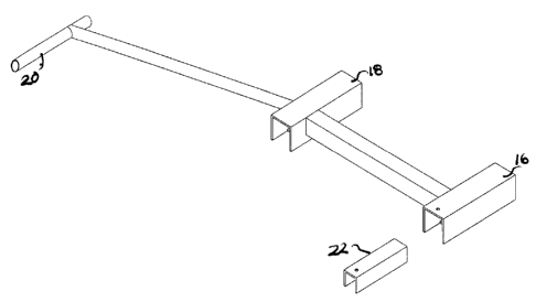
Figs. 2A to 6 illustrate a crew door lock component 10 for securing a crew
door to
prevent opening thereof. Fig. 6 illustrates the crew door lock component 10
secured
onto the crew door of the helicopter. The crew door has three handles (as seen
on the
left side of Fig. 6); namely, a top, a middle and a bottom handle.
As seen in Figs. 2A to 2D, the crew door lock component 10 comprises a bar
piece 26
to with two linear segments 12, 14 joined at an angle to each other. This
angle is
sufficient to account for any curve or angle in the door between the plane of
the crew
door between the top handle and the middle handle and the plane of the crew
door
between the middle handle and the bottom handle.
The bar piece 26 also comprises three cross pieces 16, 18, 20 positioned at
each of the
ends of the segments 12, 14 and at the intersection point. Each of these cross
pieces
16, 18, 20 corresponds with one of the handles of the crew door.
The shape of each of the cross pieces 16, 18, 20 may depend upon the shape of
the
handle to which it corresponds. For example, in the configuration shown in
Figs. 2A
to 2D it is assumed that the top handle has a cylindrical shape while the
middle and
bottom handles have a rectangular popup shape. In the configuration shown in
Figs. 2
A to 4C a top cross piece 20 has a cylindrical shape corresponding in size to
the top
cylindrical handle such that the top cross piece 20 may be slid over the top
handle for
engagement therewith. In the same configuration both a middle cross piece 18
and a
bottom cross piece 20 have a rectangular shape corresponding in size to the
middle
and bottom handles, respectively, such that the middle cross piece 18 and the
bottom
cross piece 20 may be slid over the middle and bottom handles, respectively.
The crew door lock component 10 further comprises a locking part 22 that is
engageable with the bottom cross piece 16 to secure the crew door lock
component 10
in place. The locking part 22 may be inserted into the bottom cross piece 16
(as
shown in Figs. 5A and B). When the locking part 22 is inserted into the bottom
cross
5
CA 02530074 2005-12-14
piece 16, the bottom handle of the crew door is prevented from lifting, thus
opening
of the crew door is also prevented.
Both the locking part 22 and the bottom cross piece 16 have some mechanism to
lockingly secure these two parts together. Figs. 5A and B show both the
locking part
22 and the bottom cross piece 16 have holes 24B and 24A that are aligned when
the
locking part 22 is completely inserted in the bottom cross piece 16. A known
locking
mechanism may then be inserted through the aligned holes 24A,B to secure the
locking part to the bottom cross piece 16.
Figs. 7A to 11 C illustrate a cargo door lock component 100 for securing a
cargo door
to prevent opening thereof. Fig. 8 illustrates the cargo door lock component
100
secured to the cargo door of the helicopter. The cargo door is a forward aft
sliding
door on the helicopter. The cargo door slides right to left or left to right.
A handle for
the cargo door is lifted resulting in a latch disengaging after which the door
may slide
along rollers at a top edge of the door opening.
As seen in Figs. 7A to C and 9, the cargo door lock component 100 comprises a
hook
part 102 and a pin part 104. The hook part 102 has a first end 110 with a
generally
2o hook shape for engagement with a frame part 108 of the cargo door. A second
end
112 of the hook part is shaped to receive the pin part 104 therein.
The first end 110 the hook part 102 is placed in attaching engagement with the
frame
part 108. A bracket 106 is fixedly attached to the helicopter as shown in Fig.
8 for
receiving the second end 112 of the hook part. A hole is provided in both the
bracket
106 and in the second end 112 such that the two holes may be aligned when the
hook
part 102 is attached to the frame part 108 when the cargo door is closed.
These two
holes are configured to receive the pin part 104 therein to secure the hook
part 102.
3o Figs. 12A to 15C illustrate a cargo door window lock component 200 for
securing a
cargo door window of a helicopter to prevent opening thereof. Figs. 13A and B
illustrate the cargo door window lock component 200 secured onto the cargo
door
window of the helicopter. The cargo door window has an emergency handle slot
used
to guide an emergency release lever. The emergency release lever may have a
hole
6
CA 02530074 2005-12-14
therein, which may be used for engagement of the emergency release lever and
the
cargo door window lock component 200.
As seen in Figs. 12A to C, 14 and 15A to 15C, the cargo door window lock
component 200 has a cross piece 202 that is configured to be inserted in to
the
emergency handle slot. Extending from the cross 202 is a bar piece 204
extending
orthogonally therefrom. The bar piece 204 may have a perpendicular section 206
of
sufficient size to extend over the width of the emergency release lever and a
vertical
section 208. The vertical section 208 has a far end 210 at which is located a
hole that
can be aligned with the hole in the emergency release lever. The vertical
section 208
is configured such that the hole at the far end 210 can be aligned with the
hole in the
emergency release lever.
A known locking mechanism may then be inserted through the aligned holes of
the
cargo door window lock component 200 and the emergency release lever to secure
the
cargo door window lock component 200 in the emergency handle slot, thus
prevent
the emergency release lever from sliding to open the cargo door window.
Figs. 16A to 21 C illustrate an ebay lock component 300 for securing an ebay
of a
2o helicopter to prevent opening thereof. Figs. 22A and B illustrate the ebay
lock
component 300 secured onto the ebay door of the helicopter. The ebay door is
contoured where the door meets the helicopter frame. There is a frame inside
the
ebay door on the helicopter structure.
As seen in Figs. 16A to 19, the ebay lock component 300 comprises a first part
302
and a second part 304 that are engageable with each other. The first part is
positioned
along the outside of the ebay door. The first part 302 has a generally v-
shaped portion
306 that is configured according to the shape of the ebay door. The first part
also has
an extended piece 308 that extends at an angle from the v-shaped portion 306
in
proximity to a slot 310 in the v-shaped portion 306. A hole is positioned at
the end of
the extended piece 308. The first part 302 follows the contours of the frame
of the
helicopter at the point where the ebay door and the frame meet.
7
CA 02530074 2005-12-14
The second part 304 has a hook end 312 configured to engage with a frame of
the
helicopter when the ebay door is open. Extending from the hook end 312 of the
second part 304 is bar piece 314, at the opposite end of which is a hole.
In use, the hook end 312 of the second part 304 engages with the frame of the
helicopter when the ebay door is open and the bar piece 314 extends beyond the
helicopter structure (as shown in Fig. 22). The ebay door is then closed and
the bar
piece of the second part 304 is inserted in the slot 310 of the first part
302. The first
part 302 is configured such that when the second part 304 is placed on the
frame, the
ebay door is closed and the first part 302 is engaged therewith the first part
302 has
the general shape of the ebay door at that location. The extended piece 308 of
the first
part is configured such that the hole at the bottom thereof is aligned with
the hole of
the bar piece 314 of the second part 304 when the two part are in an engaging
position.
A known locking mechanism may then be inserted through the aligned holes of
the
first part 302 and the second part 304 of the ebay lock component 300 to
prevent the
ebay door from opening.
Figs. 23A to 28C illustrate an engine compartment lock component 400 for
securing
an engine compartment of a helicopter to prevent opening thereof. Figs. 29A
and B
illustrates the engine compartment lock component 400 secured onto the engine
compartment of the helicopter. The engine compartment is accessed via a
recessed
handle provided in a handle bay that is covered by flaps. The handle bay
contains
holes that are used by the engine compartment lock component 400 for
preventing
opening of the engine compartment.
As seen in Figs. 23A to 28C, the engine compartment lock component 400 has a
first
part 402 and a second part 404. The first part 402 has a generally planar
shape with
two parallel prongs 406 extending coplanarly therefrom. The first part 402
also has a
piece 408 extending generally orthogonally proximate the center of the first
part 402.
The piece 408 has a hole place therein.
s
CA 02530074 2005-12-14
The first part 402 is configured to be placed within the engine handle bay
with the two
parallel prongs 406 inserted into holes in the engine handle bay. When place
within
the engine handle bay in this manner the first part 402 substantially covers
the engine
handle.
The second part 404 has a generally u-shaped body 412 with two prongs 410
extending from orthogonal to the u-shaped body 412 in opposite directions from
one
another. One part of the u-shaped body 412 is provided with a hole therein
(see Figs.
25A and 28B).
The second part 404 is configured to be placed within the engine handle bay on
top of
the first part 402. One of the two prongs 410 is inserted into a hole in the
engine
handle bay and then, one the one prong 410 is fully inserted, the second prong
410 is
also inserted into a hole in the engine handle bay.
When the first part 402 and the second part 404 are inserted in the engine
handle bay
as described above and shown in Fig. 29 the hole in the first part 402 aligns
with the
hole in the second part 404. A known locking mechanism may then be inserted
through the aligned holes of the first part 402 and the second part 404 of the
engine
comparhnent lock component 400 to prevent access to the engine compartment
handle.
Figs. 30A to 34C illustrate a fuel tank lock component 500 for securing a fuel
tank of
a helicopter to prevent opening thereof. Figs. 31A and B illustrates the fuel
tank lock
component 500 secured to the fuel cap of the helicopter. The fuel cap has a
top
portion with a stem connecting the top portion to a cap portion. The fuel cap
sits
inside a recess on the helicopter.
The fuel tank lock component 500 comprises a first part 502 and a second part
504
both of which are configured to fit over the top portion of the fuel cap and
remain on
the stem portion on top of the cap portion. In place, the fuel tank lock
component 500
is of a sufficient size so that the fuel cap cannot be turned to remove the
fuel cap from
the helicopter.
9
CA 02530074 2005-12-14
The first part 502 is configured with an engaging portion 506 for engaging the
top
portion of the fuel cap and a flat portion 508 that provides extra size to the
first part
502 to assist in preventing the fuel cap from turning when in place. The flat
portion
508 is provided with a hole at an end opposite the engaging portion 506. A
hole in
the engaging portion 506 is lined up with the top portion of the fuel cap.
The second part 504 is also configured with an engaging portion 510 for
engaging the
top portion of the fuel can and a flat portion 512 that provides extra size to
the second
part 504 to assist in preventing the fuel cap from turning when in place. The
flat
portion 512 is provided with a hole at an end opposite the engaging portion
510.
The hole in the engaging portions 506, 512 of the first and second parts 502,
504 are
aligned. A known locking mechanism may then be inserted through the aligned
holes
of the first and second parts 502, 504 of the fuel tank lock component 500
such that
they cannot be removed and by their size prevent the fuel cap from turning for
removal thereof.
Figs. 35A to 40C illustrate a popup handle lock component 600 for securing a
popup
handle of a helicopter to prevent opening thereof. Fig. 36 illustrates the
popup handle
lock component 600 secured to a popup handle of the helicopter.
As seen in Figs. 35A to B and 37 to 40C, the popup lock component 600 has a
first
part 602, a second part 604, and a third part 606. The first part 602 is
configured to be
slid onto a raised popup handle. The raised handle may be positioned within a
slot
608 of the first part. The first part 602 includes an extension 610 having a
hole at the
end thereof.
The second part 604 is configured to be inserted into the first part 602 from
a side of
the first part 602 opposite the extension 610. The second part 604 is
positioned over
the handle in the first part 602 to prevent the handle from being removed
vertically or
horizontally. The second part 604 includes an extension 612 with a hole at the
end
thereof.
CA 02530074 2005-12-14
The third part 606 is configured to be inserted into the first part from the
side of the
extension 610. Insertion of the third part 606 into the first part 602
prevents
horizontal movement of the handle. The third part 606 also includes an
extension 614
having a hole at the end thereof.
When the second and third parts 604, 606 are fully inserted in the first part
602, the
holes in the extensions 612, 614, 610 align. A known locking mechanism may
then
be inserted through the aligned holes of the first, second and third parts
602, 604, 606
of the popup handle lock component 600 to prevent movement of any of the parts
1 o 602, 604, 606 and the popup handle.
Figs. 41A to 42 illustrate a port window lock component 700 for securing a
port
window of a helicopter to prevent opening thereof. Fig. 43 illustrates the
port window
lock component secured to the frame of the helicopter around the port window.
The port window lock component 700 comprises a planar surface 702 and bolts
704.
The frame of the helicopter is provided with corresponding locking parts that
matingly engage with the bolts 704 provided on the port window lock component
700
to secure the planar surface 702 across the port window.
The helicopter locking system kit may comprise any of a number of combinations
of
the crew door lock component 10, the cargo door lock component 100, the cargo
door
window lock component 200, the ebay lock component 300, the engine compartment
lock component 400, the fuel tank lock component 500, the popup handle lock
component 600 and the port window lock component 700.
It is apparent to one skilled in the art that numerous modifications and
departures
from the specific embodiments described herein may be made without departing
from
the spirit and scope of the invention.
11