Note: Descriptions are shown in the official language in which they were submitted.
CA 02530242 2005-12-21
WO 2004/114322
PCT/EP2004/006837
Description
Nuclear system and method for the decompression of a
nuclear system
The invention relates to a nuclear system with a safety
containment to which a depressurization line is
connected. It relates, further, to a method for the
decompression of a system of this type.
In a nuclear power station, incidents or accident
situations must be expected to entail a possibly
significant pressure rise within the safety
containment, depending on the respective incident and
on countermeasures initiated where appropriate, such
as, for example, the inertization of the containment
atmosphere. In order to avoid possibly resulting
structural damage to the safety containment per se or
even to system components arranged in it, nuclear power
stations can be designed for an on-demand
depressurization of the containment by the discharge of
containment atmosphere (venting). For this purpose,
conventionally, a depressurization line is connected to
the safety containment of a nuclear system.
The containment atmosphere, however, normally contains
radioactive material, such as, for example, noble
gases, iodine or aerosol, which could pass into the
surroundings of the nuclear power station during
venting. Particularly in the case of comparatively
serious incidents with the possible occurrence of core
melt, airborne activity quantities (aerosols) may arise
in particularly high concentrations within the contain-
ment, so that, if there are serious leaks or if
inadmissible overpressure situations arise, a release
of significant quantities of such aerosols or activity
quantities into the surroundings of the nuclear system
CONFIRMATION COPY
CA 02530242 2005-12-21
WO 2004/114322 - 2 -
PCT/EP2004/006837
could occur. Airborne activities of this type could
cause comparatively long-term land contamination,
particularly on account of the high half-lives of
possibly entrained components, such as, for example,
iodine or cesium isotopes. In order to avoid this, the
depressurization systems provided for venting the
containment atmosphere are conventionally provided with
filter or retention devices which are intended to
prevent a release of airborne activity quantities
entrained in the containment atmosphere into the
surroundings.
For this purpose, for example, EP 0 285
845 B1
discloses a concept for the depressurization of a
nuclear power station, in which a Venturi washer
provided as a filter for the retention of airborne
activities and also a throttle device are connected in
series into a depressurization line connected to the
safety containment of the nuclear power station. The
Venturi washer in this case comprises a number of
Venturi tubes which are arranged in a washing fluid
reserved in a vessel and which can be acted upon by the
gas stream carried in the depressurization line.
The Venturi tubes in this case each comprise a nozzle-
like contraction point at which the gas stream flowing
through is accelerated to a particularly high flow
velocity. In the region of this contraction point,
ingress ports are provided for the washing fluid, the
entering washing fluid being entrained by the gas
stream flowing through. Owing to the comparatively high
flow velocity of the gas stream at this point, a
fragmentation of the washing fluid takes place,
airborne activities or aerosols entrained in the gas
stream being introduced into the liquid droplets
thereby occurring. Thus, as a result of a subsequent
droplet separation from the gas stream, it is possible
CA 02530242 2011-07-26
30905-3
- 3 -
to remove a large part of the entrained aerosols or airborne activities.
In the system described in EP 0 285 845 B1, the throttle device connected in
series
with the Venturi washer is designed for operation with what is known as
critical
depressurization. In critical depressurization, the pressure conditions in the
line
system, that is to say, in particular, the pressure drop across the throttle
device, are
established such that the medium flowing in the line flows through the
throttle device
at sound velocity. In the system according to EP 0 285 845 B1, this effect is
utilized,
in a response situation, that is to say during a depressurization of the
containment, to
set a volumetric throughput in the depressurization line which is constant
over time.
Some embodiments disclosed herein relate to a nuclear system of the
above-mentioned type, in which, in the event of depressurization, even the
finest
possible airborne activities or aerosols are retained in the Venturi washer
with
particularly high reliability, so that a release into the surroundings is
ruled out with
particularly high reliability. Furthermore, a method for the depressurization
of a
nuclear system of this type is to be specified.
As regards the nuclear system, according to an embodiment of the invention,
the
Venturi washer and the throttle device are dimensioned such that, in the event
of a
critical depressurization of an air/vapor mixture flowing in the
depressurization line, a
flow velocity of the air/vapor mixture of more than 150 m/s, preferably of
more than
200 m/s, is set at the throttle device in the Venturi washer.
According to another embodiment of the invention, there is provided a nuclear
system
with a safety containment to which is connected a depressurization line, into
which a
Venturi washer arranged in a vessel with a washing fluid and also a throttle
device
are connected in series, the Venturi washer and the throttle device being
dimensioned such that, in the event of a critical depressurization of an
air/vapor
mixture flowing in the depressurization line, with critical depressurization
occurring a
the throttle device, a flow velocity of the air/vapor mixture of more than 150
m/s is set
in the Venturi washer.
CA 02530242 2005-12-21
WO 2004/114322 - 4 -
PCT/EP2004/006837
Dimensioning in this case preferably takes place in
such a way that this high velocity prevails
predominantly in the entire operating overpressure
range of the separation device, independently of the
respective operating pressure of, for example, 2-10
bar. The Venturi pressure losses of, for example, > 0.5
bar at 1 bar and, for example, > 2 bar at pressures
> 5 bar, which occur in the case of a higher operating
pressure of the washer device for generating the
corresponding acceleration of the gases of higher
density, are in this case set passively over the entire
operating range as a result of the combination of the
Venturi washer and the throttle.
The invention proceeds in this case from the
consideration that, for the separation of airborne
activities or aerosols, a comparatively fine droplet
mist is generated in a Venturi washer or a Venturi tube
as a result of the flow conditions prevailing in the
tube interior when water is fed into the latter, the
airborne activities or aerosols to be separated being
capable of being introduced into such droplets and
therefore of being removed from the gas stream together
with these. A particularly high separation action even
for the finest possible aerosols can thus be achieved,
in that the probability with which the aerosols impinge
onto suitable water droplets, in particular with the
assistance of correspondingly high washing fluid loads,
and are included in these water droplets is kept
particularly high.
As surprisingly became apparent, precisely with regard
to Venturi tubes in which the feed of the washing fluid
into the tube interior is ensured in the manner of a
passive type of construction via the underpressure
prevailing at the contraction point and therefore
without external drive means, the probability of
impingement and inclusion of even the finest possible
CA 02530242 2005-12-21
WO 2004/114322 - 5 -
PCT/EP2004/006837
aerosols in the droplet mist rises to a considerable,
highly superproportional extent, so that, in the case
of very high flow velocities of the gas stream in the
Venturi tube, separation rates for mixed aerosols with
a particle size of about 1 m of more than 99.9% and
for comparatively fine aerosols with a particle size of
less than 0.5 m of 98% and above can be achieved in
the washing fluid. The depressurization and activity
retention system of the nuclear system is therefore
designed for maintaining such high flow velocities in
the depressurization situation.
In order in this case, precisely with regard to the
characteristic parameters, such as, for example, system
pressure, which possibly change to a great extent in
the event of an incident scenario over the entire
course of the incident, to ensure such a high
separation rate in every phase of a possible incident
and therefore to prevent to the greatest possible
extent a release of contaminating constituents into the
surroundings in every phase of an incident, the
depressurization and activity retention system of the
nuclear system is moreover designed for such a high
degree of separation virtually independently of the
system pressure prevailing in the safety containment of
the nuclear system. In this case, deliberate use is
made of the knowledge that, in the case of a throttle
device operating with what is known as critical
depressurization, the flow medium flows through said
throttle device at its sound velocity independently of
the prevailing inlet pressure.
Thus, in the state of critical depressurization, the
volumetric throughput through the throttle device is
constant independently of the prevailing inlet
pressure. A suitable combination of the Venturi washer
with the throttle device and, if appropriate, with a
metallic fine aerosol follow-up filter can thus ensure
CA 02530242 2005-12-21
WO 2004/114322 - 6 -
PCT/EP2004/006837
that, in the event of critical depressurization via the
throttle device, the volumetric throughput of the
flowing medium through the Venturi washer and, if
appropriate, through the fine aerosol follow-up filter
can be kept virtually constant independently of the
system pressure prevailing in the safety containment
and transferred to the inlet side of the throttle
device. Thus, by the throttle device being combined
with the Venturi washer, a uniformly high degree of
separation at the Venturi washer and, if appropriate,
at the fine aerosol follow-up filter can be ensured
virtually over the entire incident scenario, to be
precise as long as critical depressurization via the
throttle device occurs due to the prevailing pressure
conditions.
For this purpose, the Venturi washer and the throttle
device are in each case suitably dimensioned in the
manner of coordination with one another, so that, in
the case of critical depressurization occurring at the
throttle device, the desired flow conditions with a
particularly high flow velocity in the Venturi washer
and, if appropriate, an optimum velocity in the fine
aerosol follow-up filter are established. The minimum
flow velocity of the flow medium in the Venturi washer
which is required for the desired high degree of
separation may in this case depend on the exact
composition of the flow medium and may shift toward
higher values in the case of changing gas compositions,
for example in the case of a higher H2 fraction.
As became apparent, however, a sufficiently high degree
of separation can be achieved for the flow media
possibly occurring in the event of the depressurization
of the safety containment of a nuclear system, in that
the combination of the Venturi washer and the throttle
device is designed and dimensioned in the manner of a
calibration or reference, in such a way that, in the
,
CA 02530242 2005-12-21
WO 2004/114322 - 7 -
PCT/EP2004/006837
case of an air/vapor mixture flowing in the
depressurization line, with critical depressurization
occurring at the throttle device, a flow velocity of
the air/vapor mixture of more than 150 m/s, preferably
of more than 200 m/s, prevails in the Venturi washer.
The flow velocity of the flow medium is in this case
determined particularly in the region of the
contraction point of the respective Venturi tube.
The high velocity set via the combination of the
Venturi washer and throttle device may shift toward
even higher values in the event of changing gas
compositions, for example a higher H2 fraction, on
account of the higher sound velocity. It was found,
furthermore, that a critical maximum velocity of
approximately 270-300 m/s is established in the two-
phase mixture consisting of gas mixture and washing
fluid in the Venturi washer. Owing to the preferred
selection of a particularly high Venturi design
velocity of, for example, 200 m/s, which corresponds
approximately to 2/3 of the maximum two-phase mixture
velocity of about 300 m/s, it can thus be ensured that,
even in the presence of mixtures with a higher sound
velocity, inherently reliable throughput limitation
becomes possible and the following retention devices
are reliably protected against overload.
Advantageously, the Venturi washer comprises a
plurality of Venturi tubes. These may be designed as
what are known as short Venturi tubes, the outlets of
which are arranged below the intended desired level of
the washing fluid, so that the Venturi tubes are
immersed essentially completely in the washing fluid.
In this case, it proves to be particularly beneficial
that the higher-lying separator filter section is
protected by an overflow weir against the water
backwash occurring, so that, in this variant, too, a
reduced component height becomes possible. In this
CA 02530242 2005-12-21
WO 2004/114322 - 8 - PCT/EP2004/006837
embodiment, a combination with a following metal fiber
filter proves to be particularly advantageous for a
particularly high overall separation.
By means of Venturi nozzle tubes ejecting primarily
above the washing fluid, the water backwash determining
the component size can be minimized, and, furthermore,
a markedly higher empty tube velocity can be set in the
Venturi washing device. This results in a considerably
smaller Venturi washer diameter and a smaller component
height and also a correspondingly reduced consumption
of washing fluid. Due to the compact type of
construction made possible thereby, particularly in
combination with existing water reservoirs, the easy
integration of the device even in particularly
protected building parts of the system, such as, for
example, the reactor building, along with a reduced
outlay in terms of shielding, becomes possible.
Advantageously, a comparatively large fraction of the
Venturi tubes is therefore designed as what are known
as long Venturi tubes, the outlets of which are
arranged above the intended desired level of the
washing fluid. In order, furthermore, to prevent a
sedimentation in the region of the vessel, which could
lead to an increased maintenance and care requirement,
in a further advantageous embodiment the Venturi washer
is designed for a comparatively intensive swirling and
circulation of the washing fluid in the operating
situation. For this purpose, advantageously, a small
fraction of the Venturi tubes, preferably up to about
10%, is arranged with a downwardly directed outlet
direction within the vessel and below the desired level
of the washing fluid.
It has proved particularly beneficial for ensuring high
separation rates to set a comparatively high water load
in the Venturi washer of, for example, more than
CA 02530242 2005-12-21
WO 2004/114322 - 9 -
PCT/EP2004/006837
liters, preferably more than 10 liters, of washing
fluid per cubic meter of gas. In order to ensure this,
in a further advantageous embodiment, the Venturi tubes
have an annular slit feed extending over the nozzle
5 circumference and having an opening angle of 20 to
85 , preferably of 30 to 45 . For such a high water
load, furthermore, the Venturi tubes of the Venturi
washer advantageously have in each case a ratio of
their neck cross-sectional area to the inlet area for
the washing fluid of less than 10:1, preferably of
about 3:1. The neck cross-sectional area in this case
indicates the cross-sectional area, through which the
flow medium can flow freely, at the contraction point
within the respective Venturi tube.
In a particularly advantageous embodiment, the Venturi
tubes of the Venturi washer are designed in such a way
that the passive intake and distribution of washing
fluid are ensured into the core jet region inside the
Venturi tube on account of the underpressure generated
by the medium flowing through. For this purpose, the
Venturi tubes of the Venturi washer are advantageously
designed as round Venturi tubes with a neck width of
less than about 80 mm, preferably of less than about
40 mm, or as flat Venturi nozzles with a neck width of
less than about 100 mm. Additionally, or alternatively,
the Venturi tubes of the Venturi washer advantageously
have a ratio of height to neck width of more than 5,
preferably of more than 10.
A particularly compact type of construction for the
depressurization and activity retention system assigned
to the nuclear system, with a correspondingly reduced
outlay in terms of production and of assembly and with
the capability of easy accommodation in the protected
system region, can be achieved in that the vessel
equipped with the Venturi washer is advantageously
connected on the washing-fluid side to a further
,
CA 02530242 2005-12-21
WO 2004/114322 - 10 -
PCT/EP2004/006837
washing fluid store. Consequently, the quantity of
washing fluid reserved in the vessel itself can be kept
comparatively small, while, if required, that is to
say, in particular, in the case of the occurrence of a
consumption of washing fluid, an on-demand afterfeed
from the further washing fluid store may be provided.
The in this sense inactive, in particular larger,
washing fluid reservoir may in this case be stored in a
separate storage vessel and, in particular, serve for
topping up evaporated washing fluid. The filling level
in the vessel may in this case be set passively by the
further washing fluid store being arranged at the same
geodetic height or by means of a filling-level float
control. In this case, in particular, further water
reservoirs already provided in any case, such as, for
example, wastewater tanks, demineralized water supply
or the like, may also be utilized as a further washing
fluid store, while the on-demand feed of washing fluid
into the vessel may take place via gradients or by
means of diaphragm pumps operated from a compressed-air
accumulator, independently of the possibly failed power
supply.
Particularly effective activity retention can be
achieved in that the depressurization and activity
retention system assigned to the nuclear system is
designed, in a particularly advantageous embodiment,
for an on-demand recirculation of the airborne
activities or aerosols separated in the washing fluid
into the containment. For this purpose, in a
particularly advantageous embodiment, the vessel
provided with the Venturi washer is connected on the
washing-fluid side to the interior of the safety
containment via a feedback line of the nuclear system.
By virtue of such an embodiment, if required, that is
to say, in particular, constantly or at cyclic
intervals, the washing fluid laden with activities or
aerosols removed from the gas stream can be displaced
CA 02530242 2005-12-21
WO 2004/114322 - 11 -
PCT/EP2004/006837
completely or partially into the safety containment, so
that the activity overall requiring treatment remains
reliably in the containment. By virtue of the activity
reduction in the washing fluid achieved by means of the
feedback, resuspension effects occurring, which could
lead to the discharge of activity into the following
filter devices, are minimized.
In this case, an afterfeed of the washing fluid into
the vessel, in particular from the further washing
fluid reservoir can take place. As a result of such a
recirculation or feedback of the activities, the
activity quantity and concentration contained overall
in the washing fluid can be kept particularly low, so
that, for example, even resuspension effects leading to
the discharge of activity into following filter devices
can be kept particularly low. As a result, in
combination with the high Venturi degree of separation,
a reduction in the filter load and consequently in the
filter surfaces required is possible. Furthermore,
particularly in the case of a comparatively lengthy
venting operation over several days, a significant
improvement in activity retention, particularly with
regard to iodine and with aerosols, can be achieved.
Furthermore, as a result of such a feedback or
recirculation of the activities separated in the
Venturi washer, the decay heat occurring via the
aerosols or airborne activities is kept away from the
vessel and is displaced back into the containment, so
that the possible loads occurring as a result of this
in the vessel, for example due to fluid evaporation,
can be kept particularly low, so that a comparatively
lengthy venting operation over several days and weeks
thereby becomes possible, without the following metal
fiber fine filters being overloaded by resuspension
aerosols and iodine separation at the iodine sorption
filter being overloaded by iodine resuspension. Such
CA 02530242 2005-12-21
WO 2004/114322 - 12 -
PCT/EP2004/006837
design requirements with long-term venting operation
can therefore be fulfilled reliably and particularly
cost-effectively even for recent reactor systems with
increased requirements with regard to the control of
serious incidents, for example in combination with
independent washing fluid afterfeed, for example via
diaphragm pumps, etc., and activity recirculation into
the containment via quantity-limiting throttles.
Precisely because the evaporation of washing fluid can
thereby be avoided, the overall result, that is to say
also taking into account the possibly provided
afterfeed of washing fluid into the vessel, is an
overall reduced requirement of washing fluid.
In order to keep particularly low the number of
required leadthroughs through the safety containment of
the nuclear system which are designed with a view to
considerable safety requirements, in a further
advantageous embodiment the feedback line is in this
case connected to the interior of the safety
containment via the depressurization line.
Recirculation or feedback in this case takes place by
jet feed into the central region of the
depressurization line, so that a transfer of the
activity-laden washing fluid into the containment can
take place in countercurrent to the depressurization
gas stream.
Advantageously, the Venturi section is followed by
double gravity-type drop separation with drop
recirculation. For drop separation, preferably a
centrifugal separator, operated at high speeds
> 10 m/s, is used, which may at the same time be
employed for superheating via the generation of a
throttle effect. In the event that there is a following
metal filter stage, there is therefore no occurrence of
drops, so that this unit may also be arranged, lower-
CA 02530242 2005-12-21
WO 2004/114322 - 13 -
PCT/EP2004/006837
lying or at the same height, thus reducing the space
requirement and space height.
For further dehumidification and prefiltering, a fiber
separator in the exhaust air stream with fibers < 50 m
is advantageously combined with a prefilter unit with
fibers < 20 m, preferably in decreasing fiber
thicknesses. Fine filtering preferably takes place with
fibers of up to < 5 m, so that even the small quantity
of penetrating fine aerosols of < 0.5 m can still
largely be retained. The filter elements are preferably
produced from high-grade steel fibers. Fine filtering
may also take place with sintered fiber filters having
pore diameters < 2 m.
For effective organoiodine separation, preferably, a
molecular sieve, for example coated with silver nitrate
or other silver compounds, etc., is provided,
downstream of the throttling, for the long-term
operation of the retention system. The superheating of
the gas stream before entry into the molecular sieve in
this case expediently takes place primarily by
throttling, by an amount of at least 50% of the still
available pressure gradient of, for example, > 2 bar
with respect to the maximum operating pressure. Passive
and simple superheating of the gas stream in the iodine
sorption filter thereby becomes possible.
The retention devices, that is to say the Venturi
washer and the metal fiber filter, may also be
accommodated within a vessel at a staggered height, the
high-lying filters being provided with an inflow weir,
so that a particularly small overall height is
obtained.
In order in this case to allow feedback in the manner
of a completely passive system without recourse to
external active components, in a further advantageous
CA 02530242 2005-12-21
WO 2004/114322 - 14 -
PCT/EP2004/006837
embodiment the vessel is arranged so as to lie
geodetically at least about 5 m, preferably at least
m, higher than the outlet point of the
depressurization line from the safety containment.
5 Consequently, the feedback of the activity-laden
washing fluid through the depressurization line into
the containment is possible solely on account of the
geodetic pressure in the water column between the
depressurization line and the vessel, so that jet
10 feedback can take place in countercurrent to the gas
stream without further active aids.
Advantageously, the washing fluid is designed to a
particular extent for an effective retention of iodine
or iodine-containing compounds. For this purpose,
advantageously, a washing fluid with a pH value of at
least 9 is reserved in the vessel, and this pH value
can be obtained, for example, by the addition of NaOH,
other lyes and/or sodium thiosulfate. Adding these
chemicals to the washing fluid may advantageously lead
to the setting of a concentration in the washing fluid
of 0.5 to 5 percent by weight due to intake from a
separate chemical vessel via a jet pump located in the
freshwater stream.
A particularly compact type of construction can be
achieved in that, in a further advantageous embodiment,
the throttle device is integrated into the vessel.
By an additionally provided direct feed of cold water
completely or partially via the retention device into
the region of the reactor pressure vessel in counter-
current to the vent gas, preferably as simple emergency
measures by means of existing systems, such as, for
example, by means of a firefighting pump, or via other
systems, activity recirculation and a cooling of the
reactor core by the absorption of energy can
advantageously be achieved at the same time. Moreover,
CA 02530242 2005-12-21
WO 2004/114322 - 15 -
PCT/EP2004/006837
since higher feed quantities, with a rising filling
level in a containment, occur particularly in the early
phase of an accident, a further advantageous reduction
in the vapor/gas mixture to be sucked away and
therefore, at the same time, a reduction in the
dimensions of the retention device or suckaway device
can be achieved.
As regards the method for the depressurization of a
nuclear system of the type mentioned, the object is
achieved in that the Venturi washer is acted upon by a
flow velocity of the medium carried in the
depressurization line of more than 150 m/s, preferably
of more than 200 m/s.
The advantages achieved by means of the invention are,
in particular, that, owing to the deliberate
combination of the throttle device with the Venturi
washer, the mutually coordinated dimensioning
essentially over the entire course of an incident can
ensure that a particularly high flow velocity of the
depressurization gas stream flows through the Venturi
washer. As a result, in any event, a particularly high
separation action of more than 98% of the entrained
airborne activities or aerosols already in the washing
fluid, in particular even of the fine aerosols with a
particle size of less than 0.5 m, is ensured, so that
a release of activities into the surroundings is
avoided particularly reliably.
The depressurization and activity retention system
formed by the Venturi washer, the following throttle
device and, if appropriate, the metal fiber fine filter
in this case, in the manner of a passively operating
system, automatically ensures, in virtually all the
phases of an incident, an essentially constant through-
flow through the Venturi washer, independently of the
system pressure prevailing in the safety containment,
CA 02530242 2005-12-21
WO 2004/114322 - 16 -
PCT/EP2004/006837
so that this system is suitable, in particular, for
what is known as sliding-pressure operation, that is to
say for direct action by the system pressure in the
safety containment without a further preceding throttle
device. Depending on the flow medium carried in the
depressurization line, the virtually constant
throughput through the Venturi washer can in this case
be ensured by the critical depressurization via the
throttle device, as a result of which, independently of
the prevailing system pressure, the flow velocity of
the medium in the throttle device amounts approximately
to its sound velocity, so that the volumetric
throughput through the Venturi washer is
correspondingly also constant
approximately
independently of pressure. In the event of a gas
mixture carried in the depressurization line, moreover,
with comparatively high nozzle velocities of 150 m/s to
200 m/s, limited to < 300 m/s in the case of, for
example, a high H2 fraction, being maintained, a
mixture-independent passive throughput limitation
through the Venturi washer can be ensured even by means
of the pressure loss generated by the latter.
As a result of the combination of the high-velocity
Venturi washer device with recirculation, combined with
the following metal fiber filters, an overall degree of
separation of > 99.99 to 99.999% can be ensured even in
long-term operation, independently of the aerosol
concentration in the containment.
An exemplary embodiment of the invention is explained
in more detail with reference to a drawing, in which:
fig. 1 shows diagrammatically a nuclear system with an
assigned depressurization and activity
retention system,
fig. 2 shows a vessel with a Venturi washer, and
CA 02530242 2005-12-21
WO 2004/114322 - 17 -
PCT/EP2004/006837
fig. 3 shows a detail of a feed point of the system
according to fig. 1.
Identical parts are given the same reference symbols in
all the figures.
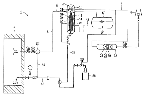
The nuclear system 1 according to fig. 1 comprises a
safety containment 2 which contains the nuclear
components provided for electricity generation and
further system components. So that structural damage to
or instabilities of the safety containment 2 can be
reliably ruled out even in the event of a comparatively
serious incident in which a sharp pressure rise within
the safety containment 2 must be expected as a result
of processes taking place within the safety containment
2, the nuclear system 1 is equipped with a
depressurization and activity retention system 4
connected to the safety containment 2. This system
makes it possible, as required, to have a deliberate
and controlled discharge of containment atmosphere,
also designated as venting, out of the safety
containment 2 into its surroundings.
The depressurization and activity retention system 4
comprises a depressurization line 6 which is connected
to the safety containment 2 and which is connected on
the outlet side to a blow-off chimney 8. To avoid a
contamination of the surroundings of the nuclear system
1 in the event of a venting or discharge of containment
atmosphere, the depressurization and activity retention
system 4 is designed for a reliable retention also of
airborne activities or aerosols contained in the
containment atmosphere. For this purpose, the
depressurization and activity retention system 4
comprises a wet washer 10 provided as a filter device
for such airborne activities or aerosols.
CA 02530242 2005-12-21
WO 2004/114322 - 18 -
PCT/EP2004/006837
The wet washer 10 itself comprises a Venturi washer 12
which is connected into the depressurization line 6 and
which is arranged in a vessel 14 having a washing fluid
W. The Venturi washer 12 comprises a number of Venturi
tubes 16 which issue with their outlets 18 into a gas
space 22 located in the vessel 14 above the desired
level 20 of the washing fluid W. A throttle device 24
is arranged in the gas space 22, and is thus integrated
into the vessel 14, and is therefore connected in
series with the Venturi washer 12 on the gas-stream
side. The throttle device 24 is itself connected on the
outlet side to a further portion of the
depressurization line 6, said further portion being
connected to the blow-off chimney 8 via a filter device
26. The filter device 26 itself comprises a metal fiber
filter 28, an intermediate throttle 30 and, following,
a molecular sieve 32. The metal fiber filter 28 is in
this case designed, in particular, as a fine filter
with fiber filter mats having a decreasing fiber
diameter of 40 gm to approximately 1 gm, so that, in
particular, even penetrating fine aerosols with a
particle size of less than 0.5 gm can be effectively
retained. Additionally or alternatively, the Venturi
washer 12 may also be followed by preferably double
gravity-type drop separation with drop recirculation.
The depressurization and activity retention system 4 of
the nuclear system 1 is designed for particularly
reliable activity retention and, in particular, for a
degree of separation of the washing device of even
comparatively fine-grained aerosols with a particle
size of less than 0.5 gm of 98% or above. For this
purpose, the Venturi washer 12 and the throttle device
24 are deliberately coordinated with one another in
terms of their dimensioning. This is based on the
design aim that, in a response situation, the
depressurization gas stream flows through the Venturi
washer 12 at a particularly high flow velocity of more
CA 02530242 2005-12-21
WO 2004/114322 - 19 -
PCT/EP2004/006837
than 150 m/s, in particular of more than 200 m/s. To be
precise, as became apparent, with such high flow
velocities, a virtually abrupt rise in the separation
rate can be achieved, and, in particular, even fine and
the finest possible aerosol particles are bound in
washing fluid droplets and are thus separated.
A suitable selection of, in particular, the flow cross
sections ensures in this case that, in virtually all
the phases of an incident scenario, such a high flow
velocity prevails in the Venturi washer 12. For this
purpose, on the one hand, the throttle device 24 is
designed, in a response situation, for operating
essentially, that is to say at a system pressure above
a limit pressure, in the range of critical
depressurization. As a result, the sound velocity
relevant for the flow medium is established in the gas
stream flowing through the throttle device 24,
independently of the system pressure prevailing in the
safety containment 2. Owing to this flow velocity in
the throttle device 24 which is independent of the
system pressure in the safety containment 2, the
volumetric throughput through the throttle device 24 is
constant essentially independently of the system
pressure prevailing in the safety containment 2, so
that the volumetric throughput through the preceding
Venturi washer 12 also correspondingly remains
constant.
To allow what is known as sliding-pressure operation,
that is to say direct action by the system pressure
prevailing in the safety containment 2, the
depressurization and activity retention system 4 is
thus designed for ensuring that the flow passes at a
correspondingly highly selected flow velocity through
the Venturi washer 12 uniformly and virtually
independently of the system pressure prevailing in the
safety containment 2. This is also achieved in that the
CA 02530242 2005-12-21
WO 2004/114322 - 20 -
PCT/EP2004/006837
relevant pressure losses in the inflow line from the
containment are minimized by the use of eccentric flaps
with a low pressure loss and having zeta values < 1,
preferably < 0.5.
As can be seen in the enlarged illustration according
to fig. 2, the Venturi washer 12 comprises a plurality
of Venturi tubes 16. The Venturi tubes 16 are in this
case fed on the gas-stream side by a common supply
system 40 connected on the inlet side to the
depressurization line 6. A comparatively large fraction
of the Venturi tubes 16 is designed as what are known
as long Venturi tubes which are arranged with their
outlets 18 above the intended desired level 20 of the
washing fluid W and which therefore issue directly into
the gas space 22 in the manner of a "freely ejecting"
arrangement. Furthermore, however, there is also
provision for preventing soiling or an impairment of
the operating behavior of the Venturi washer 12 due to
settling or sedimentation, in that a comparatively
small fraction, to be precise less than 10%, of the
Venturi tubes 16 are oriented obliquely downward. An
intensive circulation of the washing fluid W within the
vessel 14 is achieved by means of these Venturi
swirlers, so that sedimentation is reliably avoided.
In particular, the Venturi tubes 16 designed as long
Venturi tubes are designed for a comparatively high
water load of the gas stream requiring treatment of
more than 5, in particular more than 10, liters of
washing fluid W per cubic meter of gas. For this
purpose, an annular slit feed over the nozzle
circumference at an opening angle of 30 to 45 is
provided in the Venturi tubes 16 in the inlet region 42
for the washing fluid W. The dimensioning is in this
case carried out in such a way that the ratio of the
neck cross-sectional area determined at the contraction
point 44 or neck, as it is known, of each Venturi tube
CA 02530242 2005-12-21
WO 2004/114322 - 21 -
PCT/EP2004/006837
16 to the inlet area for the washing fluid W,
determined at the annular slit feed, amounts to about
3:1. Moreover, the contraction point 44 is also that
point at which the gas stream flowing through has its
maximum flow velocity; consequently, the flow velocity
taken into account for the design and coordination of
the Venturi washer 12 and of the throttle device 24 is
also determined at the contraction point 44.
In the exemplary embodiment, the Venturi tubes 16
designed as long Venturi tubes are designed as round
Venturi tubes with a neck width of less than 40 mm, so
that, in the case of a passive intake and distribution
of the washing fluid due to the underpressure generated
by the medium flowing through, a feed of the washing
fluid W into the core jet region inside the respective
Venturi tube 16 is ensured. Furthermore, the Venturi
tubes 16 have a ratio of height to neck width of more
than 10.
As may also be gathered, moreover, from the enlarged
illustration according to fig. 2, the throttle device
24 for drop separation is provided with an outflow tube
46 which issues on the outlet side into the washing
fluid W. The throttle device 24 is itself connected on
the outlet side to the depressurization line 6.
As may be seen, furthermore, from fig. 1, to allow a
particularly compact type of construction of the vessel
14, a multicomponent stock of washing fluid W is
provided. On the one hand, washing fluid W in which the
Venturi washer 12 is arranged is reserved in the vessel
14. Additionally, and to supplement this, however, the
vessel 14 is connected on the washing-fluid side to a
further washing fluid store 50 via a feed line 48. The
washing fluid store 50 may be a receptacle which is
designed specifically for this purpose and which is
selected so as to lie at a geodetically suitable height
CA 02530242 2005-12-21
WO 2004/114322 - 22 -
PCT/EP2004/006837
for a reliable afterfeed of washing fluid W into the
vessel 14, the desired level 20 of the washing fluid W
in the vessel 14 being set by means of the height, set
in the further washing fluid store 50, of the washing
fluid W reserved there. Alternatively, however, the
further washing fluid store 50 provided may also be a
water tank provided in any case, such as, for example,
a wastewater tank, a demineralized supply or the like,
while the on-demand afterfeed of washing fluid W into
the vessel 14 may take place via suitably selected
gradients or, for example, by means of diaphragm pumps
or compressed air.
Furthermore, the vessel 14 is connected on the washing-
fluid side to the interior of the safety containment 2
via a feedback line 52. This makes it possible to have,
in the manner of a feedback, a recirculation of washing
fluid W laden with airborne activities or with aerosols
out of the vessel 14 into the safety containment 2.
Consequently, by the constant or cyclic recirculation
of washing fluid W laden in this way, the activity can
be held in its entirety inside the safety containment 2
particularly reliably, so that the risk of a discharge
into the surroundings is kept particularly low.
Moreover, precisely because of such a recirculation of
the washing fluid W, the decay heat imported via the
retained activities can also be displaced consistently
out of the vessel 14 back into the safety containment
2, so that the evaporation of washing fluid W in the
vessel 14 is kept particularly low. Despite the
recirculation of washing fluid W into the interior of
the safety containment 2 and an afterfeed of washing
fluid W out of the further washing fluid store 50, the
overall consumption of washing fluid W which occurs can
consequently be kept particularly low as a result of
the avoidance of evaporation.
CA 02530242 2005-12-21
WO 2004/114322 - 23 -
PCT/EP2004/006837
As indicated by the dashed line 54, the feedback line
52 may be connected to the interior of the safety
containment 2 via the depressurization line 6. As
illustrated in the enlargement of a detail in fig. 3,
the recirculation in this case takes place in the
manner of a passive form in countercurrent to the gas
stream emerging from the safety containment 2, no
additional leadthrough through the safety containment 2
being required. In order in this case to ensure a
sufficient feed pressure for the washing fluid W to be
fed back, in the exemplary embodiment the vessel 14
together with the washing fluid W located in it is
arranged at a sufficient geodetic height, to be precise
about 10 m above the outlet point 56 of the
depressurization line 6 from the safety containment 2.
Thus, solely due to the geodetic pressure in the water
column in the feedback line 52, a sufficient feedback
pressure for the washing fluid W into the safety
containment 2 is ensured in the manner of a passive
system.
Alternatively, a cyclic feedback by the closing of the
outlet fitting in the event of overpressure in the
containment or the utilization of a separate small line
of small subcritical cross section and corresponding
action by pumps, for example a compressed-air diaphragm
pump or a centrifugal pump, may also be provided. The
components necessary for this purpose, for example a
compressed-air reservoir 58, are illustrated
diagrammatically in fig. 1.
For reliable iodine retention, the pH value in the
washing fluid W in the vessel 14 is set at an alkaline
value, in particular a value of more than 9. For this
purpose, an on-demand addition of NaOH, other lyes
and/or sodium thiosulfate takes place by intake via a
jet pump located in the freshwater stream.
CA 02530242 2005-12-21
WO 2004/114322 - 24 -
PCT/EP2004/006837
List of reference symbols
1 Nuclear system
2 Safety containment
4 Depressurization and activity retention system
6 Depressurization line
8 Blow-off chimney
Wet washer
12 Venturi washer
14 Vessel
16 Venturi tube
18 Outlet
Desired level
22 Gas space
24 Throttle device
26 Filter device
28 Metal fiber filter
Intermediate throttle
32 Molecular sieve
Supply system
42 Inlet region
44 Contraction point
46 Outflow tube
48 Feed line
Washing fluid store
52 Feedback line
54 Dashed line
56 Outlet point
58 Compressed-air reservoir
Washing fluid