Note: Descriptions are shown in the official language in which they were submitted.
CA 02530264 2005-12-14
ROOF RIDGE VENT HAVING AN INTEGRAL COVERING
AND METHOD OF INSTALLING A RIDGE VENT
BACKGROUND OF THE INVENTION
The present invention relates to a roof ridge vent that provides pathways for
the circulation of air from an attic area underlying a roof structure to the
ambient
atmosphere above the roof structure.
It is useful, and in many locales a building code requirement, that the attic
area
of a building be provided with a means to permit air exchange. Such
ventilation
prevents undue heat buildup, which can render the living quarters of the
building
uncomfortable and impose unreasonable energy requirements for cooling. Proper
ventilation of the attic area also tends to preserve the structural integrity
of the roof
and roof coverings. One method of venting the roof structure consists of
applying a
venting media over an elongate slot present along the ridge of a roof. These
types of
vents are known as ridge vents.
Examples of ridge vents are provided by U.S. Patent Nos.: 5,960,595 issued to
McCorsley et al.; 6,298,613 issued to Coupon et al.; 6,308,472 issued to
Coulton et
al.; 5,902,432 issued to Coupon et al.; 5,673,521 issued to Coulton et al.;
and
4,942,699 issued to Spinelli. The above referenced patents are owned, or co-
owned,
by Benjamin Obdyke, Inc., the assignee of the present application.
Cap shingles or like exterior building materials are installed over a ridge
vent
after the ridge vent is secured to the roof ridge. The cap shingles provide a
water
resistant covering and are selected such that they provide the roof with a
desired
exterior finished appearance. Typically, cap shingles are selected to that
they match
the appearance (ie., color, texture, etc.) of the surrounding roofing shingles
applied to
the remaining sloped portions of the roof. Thus, the vented roof ridge
structure blends
into the surrounding sloped portions of the roof providing an aesthetically
acceptable
appearance.
3o U.S. Patent Nos. 5,676,597 issued to Bettoli et al., 6,125,602 issued to
Freiborg et al., and 6,418,692 B1 and 6,530,189 B2 issued to Freshwater et al.
CA 02530264 2005-12-14
disclose composite ridge shingles and sectional ridge vents. The shingles are
constructed, for instance, of conventional asphalt compositions, and the
sectional
vents are provided as a mat of fibers or a pattern of walls that form
ventilation
channels. Thus, the installation of each shingle also simultaneously
accomplishes the
installation of a portion of a ridge vent structure. A plurality of the
composite
shingles/sectional vents are installed in overlapping fashion along the length
of the
roof ridge to complete the installation of both the sectional ridge vent and
ridge cap
shingle installation.
While the roof ridge vents disclosed in the above referenced patents may
to function in an acceptable manner, there continues to be a need for
alternatives with
respect to the design, materials and manufacturing of roof ridge vent
products. To this
end, a desired vent should permit the construction of a vented roof ridge
structure
having an aesthetically-pleasing finish appearance and should permit
improvements
with respect to the ease of installation and time required to apply a roof
ridge
covering. The vents should permit a sufficient amount of ventilating air flow
without
compromising weather infiltration resistance and should be capable of being
properly
installed in a manner requiring labor skills possessed by the average roof
installer. In
addition, the vent should be capable of efficient manufacture from inexpensive
materials and should be capable of efficient storage, shipping and handling.
BRIEF SUMMARY OF THE INVENTION
More specifically, the present invention provides a method of installing a
ridge
vent and water resistant outer covering on a roof ridge having an elongate
open
ventilation slot. The method includes the step of selecting a ridge vent
having an
2s integral water resistant outer covering that provides a desired external
appearance.
Thereafter, a continuous length of the roof ridge vent is secured on the roof
ridge such
that the continuous length completely overlies the elongate open ventilation
slot.
Thus, the single process step of securing the roof ridge vent simultaneously
accomplishes the installation of a water resistant outer covering on the
ridge. Thus,
3o the use and separate installation of cap shingles are not required.
2
CA 02530264 2005-12-14
Preferably, the method includes the step of transporting the roof ridge vent
with integral water resistant outer covering in the form of a spiral roll to
the site of the
roof. In addition, preferably the method includes the step of unrolling the
spiral roll
before or during the step of securing the vent to the roof ridge. Further, the
vent and
integral water resistant outer covering is flexed along a longitudinally-
extending
center section thereof during the step of securing the roof ridge vent so that
the ridge
vent and integral water resistant outer covering conform to the inverted-V
shape of the
roof ridge. The outer covering can be provided as a continuous strip of
material or as
a plurality of overlapping sections.
According to another aspect of the present invention, a roof ridge vent
installation is providing that includes a roof covered with roofing shingles
and having
a ridge with an elongate open ventilation slot. An elongate, continuous ridge
vent is
secured to the roof overlying the ridge and completely overlying the open
slot. The
vent has a water resistant outer covering and a ventilation material that is
integral with
the outer covering and that extends underneath the outer covering. The
ventilation
material defines an opposed pair of longitudinally-extending side edges of the
vent
and is preferably made of an openwork material that provides multiple paths of
ventilation from the open slot to the side edges of the vent. The water
resistant outer
covering has a top surface providing a desired external appearance.
2o Preferably, the water resistant outer covering is a thermoset single-ply
roofing
membrane, a thermoplastic single-ply roofing membrane, or a modified bitumen
roofing membrane. Alternatively, the water resistant outer covering can be
made of
an asphalt material and have a texture that substantially matches the texture
of the
roofing shingles. The outer covering can be provided as a continuous strip of
material
or as a plurality of overlapping sections. An outer covering having a
plurality of
overlapping sections can be utilized to cover the heads of nails used to
secure the vent
to the roof.
According to yet a further concept of the present invention, a roof ridge vent
is
provided that includes an openwork ventilation material and a water resistant
outer
3o covering that extends over the ventilation material and that is integral
therewith. The
3
CA 02530264 2005-12-14
ventilation material and integral water resistant outer covering are rollable
lengthwise
into a spiral roll for storage and transport and can be unrolled for
installation on a roof
ridge. The covering can be, for instance, any of the materials discussed
above.
BRIEF DESCRIPTION OF THE DRAWINGS
The foregoing and other objects, features and advantages of the present
invention should become apparent from the following description when taken in
conjunction with the accompanying drawings, in which:
FIG. 1 is a side elevational view of the vent according to the present
invention
1o in a spiral roll;
FIG. 2 is a cross-sectional of the vent along lines 2--2 in FIG. 1;
FIG. 3 is an elevational cross-sectional view of the roof ridge vent installed
on
a roof ridge according to the present invention; and
FIG. 4 is side elevational view of an alternate embodiment of a vent according
15 to the present invention.
DETAILED DESCRIPTION OF THE INVENTION
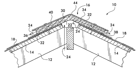
Refernng now to the drawings, FIG. 3 illustrates a roof 10 having a typical
construction which utilizes a ridge vent. The roof 10 is constructed from a
plurality of
20 rafters 12 supported at their lower ends, for instance, by front and rear
walls (not
shown) of the building. A roof deck 14 is typically constructed of plywood, or
other
suitable panels, to provide an outer sheathing of the building. The roof deck
14 is
secured to the rafters 12, extends to the end walls, and forms a ridge, or
peak, 16
therebetween. Shingles 18 or like exterior building materials are secured to
the roof
25 deck 14 to finish sloping portions of the roof 10 in accordance with
conventional
construction practices. An open slot 22 is provided along the length of the
roof ridge
16 to provide a passageway for air to vent from the underlying attic area to
the
ambient atmosphere as illustrated by arrows 24 in FIG. 3.
The shingles 18 may be conventional asphalt shingles or the like. The shingles
3o are typically of a pre-determined common color, or colors, and texture to
provide the
4
CA 02530264 2005-12-14
roof with an aesthetically pleasing exterior appearance. Although not
illustrated,
architectural shingles or other exterior building materials of a predetermined
color and
texture can also be utilized to finish sloping portions of a roof.
A roof ridge vent 30 according to the present invention includes a ventilation
component 32 and an outer waterproof covering 34. The ventilation component 32
engages the roof ridge 16 and supports the covering 34 a spaced distance above
the
underlying roof surface 16 and slot 22. In addition, the ventilation component
32
defines multiple ventilation flow paths 24 from the open slot 22 to side edge
openings,
36 and 38, of the vent 30. The covering 34 provides the finished exterior
surface of
the vented roof ridge structure and provides a waterproof cover over the slot
22 to
prevent the entry of rain, snow, and the like. The composite vent 30
eliminates the
need to separately apply cap shingles or like exterior building materials on
the vent 30
after installation thereof. Rather, the vent 30 has an upper surface 40
provided by the
outer waterproof covering 34 that provides the function of cap shingles.
The ventilation component 32 can be provided in various forms. For example,
an openwork material can be utilized as the ventilation component 32. The
openwork
material can be a single mat of fibers of a width sufficient to span the open
slot 22 as
illustrated in FIGS. 2 and 3 or can be provided as a pair of spaced-apart mats
located
on opposite sides of the open slot 22. As an alternative to a mat of fibers, a
layer of
fibers or screen formed with three dimensional cusps or like supports can be
utilized.
Alternatively, a corrugated material or a sheet of thermoplastic material
formed with a
pattern of cusps or the like can be utilized as an openwork material. The
ventilation
component 32 can also be provided by an arrangement of vertically-extending
walls,
or baffles that define open passageways therebetween. Yet another alternative
is to
utilize walls made of an air permeable material such as a fabric, screen or
the like.
According to some embodiments of the present invention, the outer covering
34 is as an elongate, continuous waterproof membrane that is bonded directly
to the
ventilation component 32 or to an intermediate sheet material (not shown)
extending
between the outer covering 34 and ventilation component 32. The intermediate
sheet
can be used as a means of securing the covering 34 and component 34 together.
The
5
CA 02530264 2005-12-14
covering 34 can be a thermoset single-ply roofing membrane such as a membrane
made of EPDM (ethylene propylene durometer) or EPR (ethylene propylene
rubber).
Alternatively, the covering 34 can be a thermoplastic single-ply roofing
membrane
such as a membrane made of thermoplastic polyolefins (TPO) or polyvinyl
chloride
(PVC). The covering 34 can also be provided as a modified bitumen roofing
membrane or like waterproof material. Yet another alternative is to utilize
cap
shingles, an asphalt material, or a composite material including asphalt
laminated to
the ventilation component 32 or intermediate sheet material.
The covering 34 is bonded directly or indirectly to the ventilation component
0 32 such that the covering 34 and ventilation component 32 form an integral
vent 30.
The covering 34 and ventilation component 32 can be adhesively secured to each
other or to opposite sides of an intermediate material. Alternatively, the
covering 34
and ventilation component 32 can be secured together utilizing thermal bonding
techniques.
An alternate embodiment of an outer covering 50 is illustrated in FIG. 4. The
outer covering 50 includes a plurality of separate overlapping sections 52.
Preferably,
one end 54 of each section 52 is bonded to the ventilation component 32 or to
an
intermediate sheet (not shown) and the other end 56 can be deflected upwardly
from
the ventilation component 32. Thus, during installation, the end 56 can be
deflected
2o upwardly, a nail 58 can be driven through the vent to secure the vent to an
underlying
roof, and thereafter, the end 56 can be returned to its original position
overlying the
head of the nail 58. The underside 60 of the end 56 can be provided with a
strip of
adhesive 62 or the like so that end 56 can be secured to an underlying section
52 after
installation of nail 58. The strip of adhesive 62 can initially be covered
with a release
sheet (not shown).
As best illustrated in FIG. 1, the vent 30 is rollable into a spiral roll 42
during
or after manufacture, is stored and transported in roll-form, and is unrolled
during or
before installation on a roof ridge. By way of example, and not by way of
limitation,
the above described ridge vent 30 can be made in indefinite, continuous
lengths
6
CA 02530264 2005-12-14
having a width "W" of about 7 to about 12 inches and a height "H" of about 0.5
to
about 1 inch. Of course, larger or smaller dimensions can also be utilized as
desired.
The vent 30 can also be provided with additional protection against weather
and/or insect infiltration, if desired. A filter material (not shown) such as
a fabric, a
non-woven fabric, a non-wicking hydrophobic fabric, a mat of filaments, an air
permeable foam plastic, a screen, or a material having a multiplicity of
closely spaced
openings permitting the flow of air therethrough can extend lengthwise
underneath the
cover 34.
With respect to the installation process of the vent 30, a vent 30 that
provides a
1o desired exterior finish can be selected. The outer covering 34, such as any
of the
above discussed membranes, can be provided in shades of black or grey or in
various
other colors and/or textures, as desired. Thus, a ridge vent 30 can be
selected based
on its exterior appearance. As one example, the coloring and/or texture of
outer
covering can be selected such that it substantially blends with or matches the
coloring
and/or texture of roofing shingles 18 or the like that are, or will be
applied, on sloping
portions of the roof 10 adjacent the roof ridge 16.
Preferably, the vent 30 is provided to the building site in a spiral roll 42,
is
unrolled lengthwise, and is aligned on the roof ridge 16. An elongate,
continuous
length of the vent 30 is then secured to the underlying roof surface 16 with
nails,
2o staples, adhesives, or the like, such that the vent 30 completely overlies
the open
elongate ventilation slot 22 formed in the roof ridge 16. As discussed above,
the
covering can include a plurality of sections having ends which can be used to
cover
nails driven through the vent. (See FIG. 4.) The roof ridge vent 30, including
the
integral water resistant outer covering 34, is flexible at least along a
longitudinally-
extending center section 44 thereof so that the roof ridge vent 30 and
integral water
resistant outer covering 34 conform to an inverted-V shape of the roof ridge
16. Since
the outer covering 34 is integral with the ventilation component 32 of the
vent 30,
installation of the outer covering 34 is accomplished simultaneous with
installation of
the ventilation component 32 thereby eliminating the need to subsequently
install cap
shingles or the like.
7
CA 02530264 2005-12-14
The above-described roof ridge vent according to the present invention
provide a uniquely constructed roll-form vent that is easy to install, is
inexpensive to
manufacture, provides a desired amount of air flow therethrough, and prevents
weather infiltration. In addition, the vent and exterior covering can be
installed
simultaneously in a single-step process.
While preferred roof ridge vents, roof ridge vent installations, and
installation
methods have been described in detail, various modifications, alterations, and
changes
may be made without departing from the spirit and scope of the vent and
installations
according to the present invention as defined in the appended claims.
l0
8