Note: Descriptions are shown in the official language in which they were submitted.
CA 02530368 2005-12-21
WO 2005/001524 PCT/US2004/020157
-1-
METHOD AND APPARATUS FOR
ACTIVATING OPTICAL MEDIA
Related Application
[O1] The present application is a continuation-in-part of United States patent
application
serial number 10/632,047 filed on July 31, 2003 and claims priority to United
States
provisional patent application serial number 60/480,686 filed on June 23,
2003, each of
which is incorporated herein by reference in its entirety.
Background
1. Field 0f the Invention
[02] The present invention generally relates to optical media systems and more
specifically relates to activating optical media devices that have a
conditional access
capability such as an optical shutter system.
2. Related Art
[~~] It is caftan desia~able for comrraerciah security and privacy reasons for
certain
conditions to be met before content stored in media such as optical discs can
be accessed.
An example is a security scheme that requires the user to enter a password
before they can
access the content stored on a compact disc ("CD"). Another example is a
rental scheme
that coaiditioz~s access to a movie stored on a digital ~rersatile disc
(~'D~D9') upon receipt of
payment by the rental company at a remote location.
[04] '7alith conventional media, conditional access schemes are effectuated
external to
the media by a host device such as a personal computer ("PC"). The password in
a
security scheme for CDs for example is typically entered into a software
application
hosted on a PC, and it is the application which affects the ability to access
the content
either through control of the optical drive in the PC, or in the method used
to decode the
content. In neither case does the CD itself participate in effectuating the
conditional
access; it is always readable.
[05] Conventional systems that rely on external devices for effectuating
conditional
access are comparatively easy to breach. Moreover, they add complexity, cost
and
undesirable burdens on the user because they require that the device used to
consume the
content has the capability to effectuate the 'conditional access scheme. That
means that
CA 02530368 2005-12-21
WO 2005/001524 PCT/US2004/020157
conditional access depends on devices like personal computers and can not be
effectuated
by conventional CD or DVD players.
[06] New types of media are emerging that incorporate the ability to
effectuate
conditional access to the content stored within them. An example is an optical
disc
incorporating an electro-optic film that changes in response to an external
signal in ways
that affect the interrogating laser's ability to access the content stored
within (e.g. it
switches from clear to opaque).
[07] Therefore, the introduction of new media with conditional access
capabilities has
created a need in the industry for an inexpensive and simple to operate
apparatus to
effectuate the conditional access features of these new forms of media.
Furthermore, it is
desirable that such an apparatus be separate from the device used to consume
the media
content. It is also highly desirable that such an apparatus be able to
effectuate conditional
access schemes involving remote and / or tlurd parties.
Summary
[08] The present invention provides an apparatus and method for activating
optical
media device that are configured with a conditional access system such as an
optical
shutter assembly. The apparatus is configured to receive an optical media
device such as a
CD, DVD, holographic memory, or optical cube and includes one or more
electrodes that
are located such that they come into physical or near physical contact with a
corresponding electrode on the optical media device. The corresponding
electrodes are in
electrical communication such that the apparatus can send data communications
to the
optical media device that effects a change in the conditional access system or
causes the
optical media device to modify its optical, physical, or visual properties.
Additionally, the
electrodes allow the apparatus to send power to the optical media device and
receive data
communications from the optical media device.
[09] The method for activating the optical media device includes establishing
communication with an activation center and sending a request for activation
to the
activation center. Upon validation of the activation request, perhaps after a
series of
challenges (e.g., user name and password) or after a payment transaction, the
activation
center sends an authorization to the apparatus. Accordingly, upon receipt of
the
authorization, the apparatus sends the authorization to the optical media
device via the
electrical communication pathway established by the corresponding electrodes.
Alternatively, the apparatus may first query the optical media device for an
identification
CA 02530368 2005-12-21
WO 2005/001524 PCT/US2004/020157
-3-
or serial number or the apparatus may read the identification or serial number
from the
optical media device. Then the identification can be sent to the activation
center so that
the appropriate authorization for the specific optical media device may be
sent back to the
apparatus.
[10] Additional advantages of the invention including alternative
communication paths
and methods of activating an optical media device will become apparent to
those having
slcill in the art after reviewing the following figures and detailed
description of the
invention.
Brief Description of the Drawings
[1l] The details of the present invention, both as to its structure and
operation, may be
gleaned in part by study of the accompanying drawings, in which like reference
numerals
refer to like parts, and in which:
[12] Figure 1 is a high level network diagram illustrating an example system
for
remotely activating an optical media device according to an embodiment of the
present
invention;
[13] Figure 2 is a block diagram illustrating an example activation center
according to
an embodiment of the present invention;
[14] Fig~n~°e 3 is a block diagram illustrating a.~~ example consmner
location according
to an embodiment of the present invention;
[l~] figure ~ is a block diagram illustrating an example activator apparatus
according
to an embodiment of the present invention;
[11~] fign~re 5 is a block diagram illustrating an ezaample optical media
device with a
conditional access mechanism according to an embodiment of the present
invention;
[17] figure 6 is a block diagram illustrating an example positioning mechanism
for
securing an optical media device in the paclcage of an activator apparatus
according to an
embodiment of the present invention;
[18] Figure 7 is a block diagram illustrating an example optical media device
engaging
a positioning mechanism to establish electrical communication according to an
embodiment of the present invention;
[19] Figure 8 is a flow diagram illustrating an example process for activating
a
conditional access means on an optical media device according to an embodiment
of the
present invention; and
CA 02530368 2005-12-21
WO 2005/001524 PCT/US2004/020157
-4-
[20] Figure 9 a flow diagram illustrating an example process for authorizing
variable
access to an optical media device according to an embodiment of the present
invention.
Detailed Description
[21] Certain embodiments as disclosed herein provide for an apparatus and
method for
providing conditional access to an optical media device that has a conditional
access
mechanism such as an optical shutter layer. For example, one method as
disclosed herein
allows for an apparatus to be communicatively coupled with an activation
center via a data
or telecommuiucations network. The apparatus is configured to make electrical
or
wireless contact with the optical media device and exchange data
communications with
the optical media device and supply power to the optical media device . The
optical media
device, upon receiving and validating an appropriate authorization code,
receives power
from the apparatus and directs the power to its optical shutter layer to
activate the optical
shutter.
[22] After reading this description it will become apparent to one skilled in
the art how
to implement the invention in various alternative embodiments and alternative
applications. However, although various embodiments of the present invention
will be
described herein, it is understood that these embodiments are presented by way
of example
only9 and not limitation. As such, this detailed description of various
alternative
embodiments should not be construed to limit the scope or breadth of the
present invention
as set forth in the appended claims.
[2~] Introduction
[2~] The content contained in optical media devices such as a CD, DV D and
laser discs
may be accessed via players that shine light (e.g., a laser) on reflective
materials contained
within the media and then 'read' the reflection. Traditionally these media are
always
readable, meaning that light can always be reflected off of the reflective
material within
the media to read the content of the media.
[25] New types of optical media devices are being developed that have optical
properties that can be altered in ways that affect their readability by
conventional reading
devices such as CD players, DVD players, game consoles, and other devices
capable of
reading from or writing to optical media devices ("players") in response to
internal or
external stimuli. For example, in the spring of 2003 an optical media device
was
announced that employed a coating that when exposed to air the coating
oxidized and after
CA 02530368 2005-12-21
WO 2005/001524 PCT/US2004/020157
-5-
a period of time such as 48 hours the coating darkened sufficiently that the
disc could no
longer be read by a conventional player.
[26] Other types of optical media devices are also being developed that
incorporate an
optical shutter that can be repeatedly activated (i.e., toggled open and
closed). The optical
shutter comprises tlun layers of materials embedded in and/or on the media and
these
layers of materials have optical properties that change in response to
internal or external
stimuli, for example electrical signals, light, acoustic energy, radio
frequency signals, and
radiation, just to name a few. An example of such an optical media device is
described in
U.S. Patent Application serial number 10/632,047 which is incorporated herein
by
reference in its entirety.
[27] An optical shutter may be configured to change state only once (e.g. open
or close)
or change state any number of times (e.g., open, close; open, close, etc.).
The optical
shutter may also be configurable with an auto decay feature whereby the
shutter is opened
and then closes at some predetermined future time. For example, the shutter
may stay
open for 2 hours or 2 days and then automatically close to provide a discrete
window of
readability for the optical media device.
[28] Additionally, these optical media devices may also change their visual
property in
order to identify, for e~~ample, whether the optical shutter is currently open
or closed. For
example, a timer or countdown or draining meter may be displayed on the
surface of the
media in order to provide a visual signal of the remaining time that the
optical shutter will
be open. Also, the optical media device may display its serial number or the
power level
of its battery in an integral electro-chromic readout or in some other
fashion. Thusq the
optical media device may modify not only its readability in response to
internal or external
stimuli, but it may also modify is visual appearance as well.
[29] Optical media devices with optical shutters can be used in a variety of
commercial
applications including on-demand and pay-per-use, and controlled distribution
of pre-lease
content, or free trial promotions. Accordingly, an apparatus and method is
needed to
activate the optical shutter on the optical media device at the consumer's
location or point-
of presence ("POP") in a controlled manner that facilitates different business
objectives
(e.g., collection of rental fees coordinated with theatrical release).
Activation of the
optical media device is needed for the content on the media to be available to
the
consumer.
[30] Fig. 1 is a high level network diagram illustrating an example system 10
for
remotely activating an optical media device according to an embodiment of the
present
CA 02530368 2005-12-21
WO 2005/001524 PCT/US2004/020157
-6-
invention. In the illustrated embodiment, the system 10 comprises a consumer
20 that is
communicatively coupled with an activation center 30 via a network 40. The
subject
optical media device (not shown) is located at the POP of the consumer 20.
[31] The consumer 20 preferably has the subject optical media device and an
apparatus
configured to activate the device. The consumer 20 initiates the process of
activating the
conditional access mechanism, for example by merely inserting the optical
media device
into the apparatus or by pressing a button or providing some other input or
instruction after
the optical media device has been inserted into the apparatus. In one
embodiment, the
optical media device is not inserted into or physically connected to the
apparatus, although
the optical media device is cormnunicatively coupled with the apparatus.
[32] The consumer 20 can gain access to the network 40 in a variety of ways.
For
example, the consumer 20 may have a personal computer that is connected to a
local area
data network via a conventional telephonic modem or a cable modem. The local
area data
networlc can preferably be part of the global community of networks
colloquially referred
to as the Internet. The consumer 20 may also gain access to network 40 via a
wireless
communication device and a local wireless communication network. The consumer
20
may also gain access to the network 40 through the apparatus for activating
the optical
media device. It vJill be readily apparent to those having skill in the art a
plurality of
additional ways for consumer 20 to gain access to network 4~0.
[33] Activation center 30 may be located in any geographical region and is
also
connected to network 4~0, perhaps through an intermediary local area network
(not shown).
The actij,~ation center 30 can be implemented as a standard personal or
ser~rer computer
and is preferably is communicatively coupled with one or more consumers via
network 40
and is preferably configured to handle a plurality of consumer requests at the
same time.
Additionally, there may be multiple activation centers 30, for example a
discrete activation
center 30 may be employed for a particular content provider while a different
content
provider may employ its own discrete activation center 30. The activation
center 30 may
also be in the same location as the consumer 20, in which case the network 40
may be a
local area network, a personal area network, a peer-to-peer network, or a
direct wired or
wireless link (such as a Bluetooth or radio frequency link).
[34] Network 40 can be any of a variety of networks or group of interconnected
networks. Networlc 40 can be a telecommunications network capable of
establishing
circuit communications between network devices. Network 40 may also be a data
communications network capable of non-dedicated paclcet based data
communications, for
CA 02530368 2005-12-21
WO 2005/001524 PCT/US2004/020157
example implementing the TCP/IP protocol. Network 40 may also be any
combination of
networlcs including local area networks, wide area networks, wireless
networks, wired
networlcs, circuit switched networks, and packet switched networks.
[35] Fig. 2 is a block diagram illustrating an example activation center 30
according to
an embodiment of the present invention. In the illustrated embodiment, the
activation
center 30 has an authorization authority 50. The authorization authority 50
may be
implemented in software and is configured to receive communications from a
consumer
requesting access to an optical media device. The authorization authority 50
can then
validate the request or just respond to the request with an authorization code
that will
activate the optical shutter on the optical media device, for example causing
it to open.
The authorization authority 50 preferably has access to a local or remote
database (not
shown) of optical media device identifiers and corresponding authorization
codes. The
authorization authority 50 may also have access to a database with username
and password
combinations in order to validate consumers or individual apparatus that are
requesting an
authorization code to access an optical media device.
[36] Note that the activation authority may be remote (e.g. accessed via the
Internet or
phone network) or embodied in a portable device with the ability to authorize
the
activation via stored value and instructions. In such an embodiment where the
activation
authority resides in a portable device (e.g., smart card or personal digital
assistant
("PDA")), the activation authority preferably has a pre-paid authorization.
Additionally,
in such an embodiment, the activation center may still be a remote entity that
rnanufac.tures and sells tlae pre-paid cards or distributes electr~nicalhr
access codes to
PDAs or smart phones or other portable electronic devices and storage devices.
[37] Fig. 3 is a block diagram illustrating an example consumer 20 location
according
to an embodiment of the present invention. In the illustrated embodiment, the
activator 60
is co-located with the consumer's 20 P~P. Preferably, the activator 60 is
communicatively coupled with the network 40, as previously described with
respect to
Fig. 1. Implementation of the activator 60 may be integrated with a personal
or server
computer or integrated with an optical media device player such as a CD
player, DVD
player, game console, or other device capable of reading from or writing to an
optical
media device. Preferably, however, the activator 60 is a stand alone apparatus
capable of
receiving an optical media device and establishing, communication with both
the optical
media device and the activation center 60 via the networlc 40.
CA 02530368 2005-12-21
WO 2005/001524 PCT/US2004/020157
_$_
[38] Fig. 4 is a block diagram illustrating an example activator 60 apparatus
according
to an embodiment of the present invention. In the illustrated embodiment, the
activator 60
comprises a package 80 that provides the physical housing for many of the
components of
the activator 60, including the actuator 70 and the positioning mechanism 90.
A data
storage area 85 is shown external to the paclcage 80 but is preferably
incorporated into the
package 80 and available for use by the components therein, such as the
actuator 70 and
the communication manager 110.
[39] The positioning mechanism 90 is used to secure an optical media device
100
(which may or may not be present in the activator 60). The actuator 70 may be
implemented as a microprocessor and is communicatively coupled with: (1) one
or more
electrodes 190 via a communication path 120; (2) a communication manager 110
via a
communication path 130; and (3) an internal or external power source 140 via a
communication path 125. The power source 140 may be a replaceable internal
battery or
it may optionally be a converter that is connected to an external power source
via power
connector 150, as will be understood by those having skill in the art.
[40] The communication manager 110 is communicatively coupled with the network
40. The communication manager 110 may comprise a microphone and spealcer
assembly
that allows the activator 60 to connect with a remote activation center via a
telecommunications network over a circuit switched connection. The
communication
manager 110 may alternatively communicate via a wireless local loop that
connects the
activator 60 to a proximal wireless device that is configured to communicate
with an
actuation center over a teleconmunication or data network. The communication
manager
110 may also be implemented in a direct connect configuration wherein the
communication manager 110 comprises a standard modem or a cable modem for
accessing network 40. Additionally, the communication manager 110 maybe
implemented as a wireless communication device that is capable of establishing
a direct
connection with the activation center via the network 40. The communication
manager
110 may also comprise a wired connection to an external modem, a PISA, or
other device
capable of providing access to network 40. The communication manager 110 may
also
comprise a wired or wireless connection to a card reader, a smart card, an
electronic wallet
or other device that includes the authorization authority capability.
[41] The activator 60 may also be configured with an optional input device 155
that
may be integral to the package 80 or external and connected to the paclcage 80
via a cable
or wireless linlc, such as a radio frequency ("RF") or Bluetooth link. The
input device 155
CA 02530368 2005-12-21
WO 2005/001524 PCT/US2004/020157
-S-
can preferably allow a consumer to input a serial number or other
identification or
pertinent information into the activator to assist in activating or otherwise
manipulating
the optical media device. The input device 155 may also comprise a card
reader, smart
card, PDA, electronic wallet or other device that includes the authorization
authority
capability.
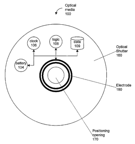
[42] Fig. 5 is a block diagram illustrating an example optical media device
100 with an
optical shutter 160 according to an embodiment of the present invention. In
the illustrated
embodiment, the optical media device 100 comprises an optical shutter 160, one
or more
electrodes 180, and a positioning hole 170. The one or more electrodes 180 are
illustrated
as a single electrode in a complete ring around the optical media device 100.
Advantageously, this configuration helps to ensure that electrical
communication will be
established when the optical media device 100 is inserted into or otherwise
connected to
the activator apparatus. Alternatively, a single or several electrodes 180 may
be placed on
the optical media device 100 and the activator apparatus may have an electrode
configured
in a ring.
[43] Additionally, there are several components layered within the optical
media device
100 including logic 108, data 109, clock 106, and battery 104. Advantageously,
these
components may all be directly or indirectly connected to the one or more
electrodes 180.
In one embodiment, the battery 104 is separately connected to the electrodes
so that it may
receive a chaxge from the power supply, as will be understood by those having
shill in the
art.
[44] In on a embodirrmntg the logic is configured to activate or deactivate
the shutter
mechanism or otherwise participate in the conditional access scheme for the
optical media
device 100. The data 109 may house a serial number or other identifier for the
particular
optical media device 100. Preferably, the data stored in data 109 can be
updated or
otherwise modified by logic 108. In one embodiment, the logic 108 is
configured to
provide the serial number or other information stored in data 109 in response
to a request
for such information, for example a request from the actuator 70.
[45] Additionally, the clock 106 is preferably capable of tracking elapsed
time or
otherwise maintain an association with real time such that the logic 108 may
control the
conditional access mechanism such as an optical shutter and implement a
discrete window
of time that the optical media device 100 is readable. The battery 104 is
preferably
rechargeable and has a renewable charge time of 5 days or longer.
CA 02530368 2005-12-21
WO 2005/001524 PCT/US2004/020157
-10-
[46] The optical shutter 160 is a material that is layered into, onto or
otherwise integral
to the optical media device 100 to be activated and that changes the optical
properties of
the media 100 (e.g., its appearance, ability to pass-through and reflect light
(especially
light at specific frequencies), and to reveal embedded information, etc.) in
response to
internal or external stimuli. More than one type of material may be layered
into, onto or
otherwise added to the optical media device 100 as part of the optical shutter
160. The
material need not be uniformly layered or uniformly distributed throughout the
optical
media 100.
[47] An optical shutter 160 preferably includes all the circuitry incorporated
into, onto
or otherwise integral to the optical media device 100 that is necessary or
desirable for: (1)
activating the shutter - changing its optical properties in response to
internal or external
stimulus; or (2) changing the optical properties of the optical media 100 in
response to
internal or external stimulus.
[48] Fig. 6 is a bloclc diagram illustrating an example positioning mechanism
90 for
securing an optical media device in the package of an activator apparatus
according to an
embodiment of the present invention. In the illustrated embodiment, the
positioning
mechanism 90 is a raised cylinder that is intended to engage the positioning
opening of an
optical media device. For example, CI~s and I~~L~s typically have a
positioning opening
in the center of the disk that is configured to engage a mechanism such as
positioning
mechanism 90 in order to secure the optical media device in place. The
positioning
mechanism 90 may also take foams alternative to a raised cylinder depending on
the cost
of~ implementation and the form factor of the optical media device.
[49] The positioning mechanism 90 may also have one or more integral
electrodes 190
that are configured to engage the corresponding electrodes on the optical
media device. In
one embodiment, the electrode 190 may be configured as a ring to that a
corresponding
electrode on an optical media device will engage the electrode 190 regardless
of the radial
orientation of the optical media device. Preferably, the one or more
electrodes 190 are
electrically and/or communicatively coupled with communication path 120 so
that the
electrodes 190 are communicatively linked with the actuator. The one or more
electrodes
190 may also be separately electrically coupled with the power source (e.g.,
via
communication path 125 described in Fig. 4) so that the battery on the optical
media
device may be charged.
[50] In one embodiment, the positioning mechanism 90 may be enhanced in ways
that
facilitate the contact (or proximity contact) communication between the
actuator and the
CA 02530368 2005-12-21
WO 2005/001524 PCT/US2004/020157
-11-
optical media device to be activated (e.g., made from or coated with
conductive materials
or including a spring mechanism to reinforce physical or near physical
contact).
[51] Fig. 7 is a block diagram illustrating an example optical media device
100
engaging a positioning mechanism 90 to establish electrical communication
according to
an embodiment of the present invention. In the illustrated embodiment, the
positioning
opening 170 in the optical media device 100 receives the positioning mechanism
90 in
order to properly locate the electrodes 180 that are integral with the optical
media device
100 with the electrodes 190 that are incorporated into the activator
apparatus. Preferably,
once the optical media device 100 is seated, the one or more electrodes 180
are positioned
such that they are in electrical communication with the one or more electrodes
190, which
in turn are cormnunicatively coupled via communication path 120 to the
actuator 70 as
described above with respect to Fig. 4. Advantageously, the electrodes do not
have to be
in actual physical contact to be in electrical communication.
[52] Fig. 8 is a flow diagram illustrating an example process for activating a
conditional
access means on an optical media device according to an embodiment of the
present
invention. Initially, in step 200, the activator establishes a session with a
remote activation
center. A session may be established, for example, by placing a telephone call
to the
acti~ration centere The call can be placed by a consumers can be placed by the
activator
apparatus in response to an instruction from a consumer, or alternatively the
call can be
placed by the activator apparatus pursuant to a mechanical or computer-
electrical trigger.
[~~] A session may also be established over a data communications network, for
e:~ample v~ith a~ rmn~ate login procedure9 remote pr~cedure call9 instant
message, chatq
email or other type of rem~te data connection. In one embodiment, if the
connnunication
manager of the activator is implemented as a modem a remote data session may
be
established over a telecommunications network with a modem at each end of the
network.
In the case of a data communications network, the session may also be
implemented as a
voice-over-Internet-protocol ("VQIP") call.
[54] When a particular activation center serves to activate only one type of
optical
media device, once a session has been established, the activator receives an
authorization
signal from the activation center, as shown in step 205. In one embodiment,
the
authorization signal may be an acoustic signal from the handset of a phone
held by the
consumer/user in proximity to the activator apparatus. Alternatively, the
authorization
signal can be a data paclcet comprising a particular code, for example, that
matches a code
CA 02530368 2005-12-21
WO 2005/001524 PCT/US2004/020157
-12-
stored in the data storage area on the optical media device and comparable by
the logic
integral to the optical media device.
[55] In an alternative embodiment, the activation center may serve to activate
a variety
of different types of optical media devices and therefore the activation
center may require
an identifier or serial number for the particular optical media device to be
activated. In
such an embodiment, the consumer may provide the serial number via voice or
lceyboard
input. Alternatively, the activator may read the identifier from the optical
media device or
query the optical media device and receive a response that includes the
identifier. In such
an embodiment, the identifier may be supplied to the activation center when
the session is
established or in response to a subsequent query from the activation center.
[56] Once the activator has received the authorization signal from the
activation center,
the signal is sent to the optical media device, as illustrated in step 210. If
the signal is
acoustic, the signal can be played so that a transceiver on the activator
apparatus receives
the acoustic signal and converts it into an electrical signal that is sent to
the logic on the
optical media device or causes power to be sent to the optical media' device.
If the signal
is not acoustic, the signal can be sent to the optical media device for
processing by the
logic or the activator may just allow power to flow to the conditional access
mechanism on
the optical media device. In response to the input received from the
activator, the
conditional access mechanism is activated in order to change the state of the
optical media
device, as seen in step 215. In alternative embodiments, the response may
instead be to
affect some other aspect of the optical media device, for ez~ample to change
information
that is stored in the data storage area that is integral to the optical media
device.
[~7] Fig. ~ a flow diagram illustrating an example proeess for authorizing
variable
access to an optical media device according to an embodiment of the present
invention.
Initially, the activator has already established a session with the activation
center and then
in step 250 the activator receives a query from the activation center.
Typically, such a
query may be a request for a serial number or identifier in order to uniquely
determine the
particular optical media device that is to be accessed. The query may also be
a request for
an identifier for the activator itself or for other information stored by the
activator or
provided by the consumer/user.
[5~] In response, the activator may read a serial number or other identifier
off of the
optical media device. Such a reading may be direct read instruction to the
logic that
results in the serial number being provided from the data store on the optical
media device.
Alternatively, if the logic is more sophisticated then the reading may be
implemented as a
CA 02530368 2005-12-21
WO 2005/001524 PCT/US2004/020157
-13-
query to the logic that preferably provides the same results. Optionally, the
serial number
may be provided by the consumer through a~eypad that is connected to or
integral with
the activator apparatus.
[59] Once the identifier is obtained, in step 260 a response containing the
identifier is
sent to the activation center. The activation center, in response, sends an
authorization
signal to the activator which is received by the activator in step 265. Next,
in step 270 the
activator sends the authorization to the optical media device after which the
conditional
access mechanism is activated, as illustrated in step 275. As previously
described, other
functions may also be carried out in place of activating (or deactivating) the
conditional
access mechanism.
[60] While the particular systems and methods herein shown and described in
detail are
fully capable of attaining the above described objects of this invention, it
is to be
understood that the description and drawings presented herein represent a
presently
preferred embodiment of the invention and are therefore representative of the
subject
matter which is broadly contemplated by the present invention. It is further
understood
that the scope of the present invention fully encompasses other embodiments
that may
become obvious to those spilled in the art and that the scope of the present
invention is
accordingly limited by nothing other than the appended claims.