Note: Descriptions are shown in the official language in which they were submitted.
CA 02530512 2005-12-22
WO 2004/114232 PCT/IT2003/000395
1
DEVICE FOR MOVING OBJECTS CONTAINED INSIDE AN AUTOMATIC VENDING MACHINE
**********
TECHNICAL FIELD
The present invention refers to a device for the
manipulation and movement of objects contained inside an
automatic dispensing machine. -
More in particular, this invention refers to a
manipulating device that makes it possible to pick up an
object present in a predetermined position inside an
automatic dispensing machine, and to move this object in
such a way as to make it available to a user outside the
dispensing machine.
The invention can be mainly applied in the sector of
the manufacture of automatic dispensing machines.
BACKGROUND ART
Various types of automatic dispensing machines are
known to the background art, covering a wide variety of
applications, activated by the insertion of tokens, notes,
credit or debit cards, magnetic or electronic cards, etc.
These automatic dispensing machines, which can be
installed indoors or outdoors, generally consist of a
casing, normally in. metal, containing a fixed or mobile
magazine with a plurality of housings, inside each of which
a certain object is positioned.
Payment of a certain amount (by coins, tokens, notes,
electronic or magnetic cards, etc.) gives the user the
possibility of access to one of these housings, or to the
SUBSTITUTE SHEET (RULE 26)
CA 02530512 2005-12-22
WO 2004/114232 PCT/IT2003/000395
2
object it contains.
A wide variety of objects can be contained in these
automatic dispensing machines, for example cigarettes,
flowers, food and drink, video cassettes, audio or video
disks, medical or paramedical items, etc.
By way of example, European patent application no. EP-
A-577121 describes an automatic device for the distribution
of audiovisual and digital recorded items.
This device comprises a fixed magazine, consisting of a
plurality of adjacent housings arranged in respective rows
or columns, each housing being designed to contain one of
the said items, at least one manipulating unit to pick up
and discharge the items externally through a slot, a device
'for reading an identification label associated with each
item, a device through which the user can select a certain
item, and automatic payment means which allow withdrawal of
the item.
The housings have different shapes and sizes according
to the respective shapes of the items they are designed to
accommodate .
The manipulation unit comprises a pair of parallel
carriages which move along vertical guides and a cursor
which moves along a second horizontal guide connected to
these carriages; a blocking- element is rigidly associated
with this cursor for the manipulation of the items.
This blocking element comprises mobile gripper jaws and
a device for automatically varying the distance between the
w gripper jaws along another guide.
The entire device -is extremely complicated as regards
construction since it requires the presence of numerous
motors, the movements of which must be coordinated and
CA 02530512 2005-12-22
WO 2004/114232 PCT/IT2003/000395
3
synchronized with great precision.
Furthermore, due to the bulky structure of the machine,
which has one or more fixed magazines, the delivery times of
the items are quite long which can be annoying to the user
of the machine.
Another automatic dispensing machine for video
cassettes and/or DVDs, known to the background art,
generally comprises a magazine enclosed in a casing and an
interface unit easily accessible from the outside.
With reference to figure 1, the magazine 30 usually
consists of a series of housings arranged vertically one
above the other, each being defined by a pair of profiles
31, 31' which protrude from.a support upright (not shown in
the figure), at predetermined intervals vertically.
Pairs of adjacent profiles 31-31', 32-32' etc. form
housings designed to accommodate cases for recorded objects
of different types, in particular video cassettes 33 and/or
DVDs 34.
The distance between two consecutive profiles is such
as to form a housing to accommodate DVD cases, which are
supported by two coplanar ledges projecting towards each
other from two respective consecutive profiles belonging to
the same row, or video cassettes which are also supported by
a pair of ledges on the profiles.
As can be seen in figure 1, each ledge is integral with
the respective profile 31, 31' .... with a central
connecting bar that gives the ledge-bar pair a "double T"
cross-section.
The .video cassette 33 and/or DVD 34 recorded objects
enclosed in their respective cases are normally moved from
and to the respective housings by means of an appropriate
CA 02530512 2005-12-22
WO 2004/114232 PCT/IT2003/000395
movement device known to the background art.
The device (not shown in the figures) usually consists
of a carriage, connected to an upright positioned at the
side of the magazine, and is moved and controlled
automatically within a vertical plane identified by two axes
conventionally called X, Y.
In particular, the movement along the axis Y takes
place along the aforesaid upright, while the movement along
the axis X takes place in front of the respective magazine
housings.
The carriage also comprises a pair of arms which extend
at right angles, therefore along the axis conventionally
called Z, to the movement plane of the carriage.
These arms generally move within the free space between
two vertically adjacent profiles.
The .arms comprise conveyor belts with a relatively
irregular surface, which are able to move a case in the
direction identified by the axis Z.
When one wishes to withdraw a case from a predetermined
position inside the magazine, the carriage is first moved
along the respective axes Y and X with the aim of
positioning the arms of the carriage immediately below the
case in question. The arms are then raised in such a way as
to slightly raise the case and thus place it in contact with
the conveyor belts, which are activated in order to move the
case. The case moves along the axis Z into a special housing
in the carriage. The carriage moves back along the axes Y
and X until it reaches a case discharge station where, in a
similar way, the case is transferred from the carriage to a
discharge device.
The same procedure is carried out, in reverse order, to
CA 02530512 2005-12-22
WO 2004/114232 PCT/IT2003/000395
S
insert a case in a respective housing.
The movement device described above presents a series
of drawbacks and disadvantages which limit its possibility
of use .
One drawback is represented by the fact that the
withdrawal and the insertion of the video cassette or DVD by
means of belts requires relatively extensive maneuvering
spaces for the carriage, reducing maneuverability and
rapidity of the movements.
Another drawback is represented by the fact that since
the profiles need gaps and slots for the passage of the
carriage arms, they constitute a relatively deformable
structure since the ledges and the bars, designed to support
the product; protrude from the upright, undergoing flexural
effects that compromise the positioning precision of the
housing for the product.
A further drawback is represented by the fact that the
belts work by friction, thus being subject to wear and tear
and unable to guarantee sufficient reliability. in carrying
out their job.
Yet another drawback that cannot be ignored consists of
the fact that the upright on which the carriage is
positioned is housed in a space at the side of the magazine,
increasing the overall dimensions of the dispensing machine.
Solutions have already been proposed which use gripping
means in place of the belts, for example the use of side
grippers working with a non-continuous gripping technique
known as "pilgrim pxocess".
While ~ the.s.e solutions resolve some of the typical
problems mentioned above, they are not without drawbacks due
to the slow speed of the working operations and to the
CA 02530512 2005-12-22
WO 2004/114232 PCT/IT2003/000395
6
difficulty of gripping objects with a limited thickness such
as, for example, DVD cases.
DESCRIPTION OF THE INVENTION
The present invention proposes to provide a device for
manipulating and moving objects contained inside an
automatic dispensing machine and which can eliminate or
significantly reduce the drawbacks described above.
This invention also proposes to provide a movement
device which is safe, reliable and long-lasting.
The last but not least aim of this invention is to
provide a device for manipulating and moving objects
contained inside an automatic dispensing machine and which
.'can be produced with accuracy and precision so as to be
qualitatively advantageous.
This is achieved by means of a device for manipulating
and moving objects contained inside an automatic dispensing
machine with the features described in the main claim.
The dependent claims described advantageous forms of
embodiment of the invention.
According to the invention, the device for manipulating
and moving objects contained inside a magazine equipped with
a plurality of housings, each designed to accommodate an
object to be transferred, moves along a plane (X, Y) in front
of .the magazine and can be positioned in front of each of
the housings. According to the invention, the device
. comprises a cell (11) to accommodate an object and a
carriage, moving in a~direction (Z) at right angles to the
plane (X,Y) on .respective guides in the lower part,of the
cell .
The device also comprises a slide mechanically
CA 02530512 2005-12-22
WO 2004/114232 PCT/IT2003/000395
7
connected to the carriage and moving in the same direction
as the carriage; typically, the upper surface of the
carriage and of the slide form a support surface for the
object to be transferred. The device also comprises a
mechanism to activate the carriage and the slide through an
appropriate source of motion.
According to an advantageous embodiment of the
invention, the slide has a longitudinal slot, substantially
parallel to its direction of movement, designed to house a
respective bar comprising elastic loading means designed to
allow minimal movements of the bar.
At each longitudinal end, the bar is equipped with a
stop tooth, in operation projecting at right angles from the
slide support surface, designed to~restrain the product
during withdrawal and insertion.
The reduced movements of the bar with respect to the
slide, limited by the elastic loading means, allow
adaptation of the stop teeth to the dimensions of the
product in order to compensate for slight positioning
inaccuracies inside the magazine housings.
The elastic loading means consist of leaf springs which
can be fixed to the central part of the slide and striking
against the respective pins on the bar.
Advantageously there is a single source of motion,
consisting of an electric motor.
According to the invention, the kinematic connection
between the carriage and the source of motion for the
movement. on the respective guides consists of a gear-rack
pair. -.
Advantageously, the slide comprises a rack designed to
engage with end gear wheels of a step-up gear train
CA 02530512 2005-12-22
WO 2004/114232 PCT/IT2003/000395
8
receiving motion from a primary drive gear cooperating with
the source of motion.
The step-up gear train guarantees a high translation
speed of the slide in working conditions both during the
forward and return movements of the carriage.
The translation of the moving parts, carried out by
gears, guarantees high positioning precision and excellent
reliability with respect to movement made by conveyor belts
or toothed belts.
~ The cell can move inside the magazine, simultaneously
combining motions in two directions, reaching a
predetermined position more quickly thanks to the fact that
the withdrawal and insertion of products takes place in
front of the magazine that houses them.
I5
DESCRIPTION OF THE DRAWINGS
Other features and advantages of the invention will
become evident on reading the following description of some
form of embodiment of the invention, given as non-binding
examples, with the help of the enclosed drawings, in which:
- figure 1 is a schematic perspective view of part of a
magazine designed to house various types of recorded
objects;
- figure 2 represents a schematic view from above of a
2S carriage equipped with a manipulating and movement
device according to the present invention; and
- figure 3 shows an enlarged plan view, with details in
cross-section, of a gear train of the carriage in the
previous figures...
DESCRIPTION OF A FORM OF EMBODIMENT
CA 02530512 2005-12-22
WO 2004/114232 PCT/IT2003/000395
9
In figure 2, the reference number 10 generally
indicates a device for manipulating and moving objects
contained inside an automatic dispensing machine, comprising
a magazine for the storage of these objects.
The embodiment described below consists of an automatic
dispenser of video cassettes or DVDs, of the type normally
used in rental outlets. It is nevertheless clear that the
invention is not limited to the use of the manipulating and
movement device for dispensers of this type, and the device
in question can easily be used for the movement of objects
of any kind such as, for example, flowers, tobacconist or
photography items, medical and paramedical articles, etc.
The movement device 10 comprises a cell 11 which moves,
through appropriate kinematic motion, on a vertical plane
(X,Y) positioned in front of a magazine 30 (see fig. 1)
comprising a plurality of housings, each designed to
accommodate an object 33, 34 to be transferred from the
housing to a discharge device or vice versa.
In general, the movement of the device 10 along the
plane is controlled by an appropriate electronic unit,
equipped with means for memorising the position of each
magazine housing. Tn the case in question, which refers to
an automatic dispenser of recorded objects, the electronic
control unit can be equipped with a plurality of electronic
circuits and sensors for the identification of particular
recorded objects and their transfer. This control
electronics is known to the background art and is not part
of the present invention.
The cell 11 of the movement device 10 is bordered at
the sides by pairs of guides I2-12 ~ or 13-13 ~ . In. the case
in question, the cell 11 is designed to house a product, for
CA 02530512 2005-12-22
WO 2004/114232 PCT/IT2003/000395
example a video cassette or a DVD, during the transfer phase
from a housing to the discharge device and vice versa.
The lower part of the cell 11 is equipped with a pair
of guides 14-14', in the case in question consisting of two
5 parallel cylindrical bars, for the sliding of a carriage 15
which has a pair of holes for housing these guides 14-14'.
The carriage I5 is integral with a side casing 17
designed to house a source of motion, for example an
electric motor 16.
10 Furthermore, the body of the carriage 15 presents a
central longitudinal cavity and two side guides, designed to
house a slide 18 which, together with the upper surface of
the carriage 15, provides a support surface for the product
to be transferred.
According to a particularly advantageous embodiment of
the invention, the slide 18 has a longitudinal slit,
extending along its entire length and designed to house a
bar 19 equipped, at each longitudinal end, with a respective
striker element 20-20' protruding beyond the support surface
of the slide 18.
Advantageously, the bar~l9 comprises elastic loading
means 21-21', designed to return it to the central rest
position from any limited longitudinal travels with respect
to the slide 18, in order to adapt the positioning of the
striker elements 20-20' with respect to the edges of the
product to be picked up.
The presence of these elastic loading means 21-21' also
makes it possible' to directly compensate for any
irregularities in the vertical layout of the magazine and
its housings for the products to be transferred.
These elastic loading means can consist of leaf springs
CA 02530512 2005-12-22
WO 2004/114232 PCT/IT2003/000395
IZ
21-21' which can be fixed to the central part of the slide
18 and strike against the respective pins 22-22' of the bar
19.
The side of the carriage 15, adjacent to the casing 17,
is equipped with a protective guard 23 for a step-up gear
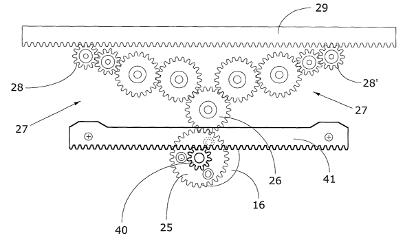
train 24 (see figure 3).
The step-up gear train 24 comprises a primary driving
wheel 25, integral with the shaft of the electric motor,
engaging with a central gear wheel 26 which transmits the
motion to two lateral trains of spur gears 27-27', each
ending with a small driven gear wheel 28-28'.
Each driven gear wheel 28-28' engages with a rack 29
integral with one side of the slide 18 which can thus move
out of and into the carriage 15 according to the rotation
direction transmitted by the motor shaft to the primary gear
25.
A second driving gear 40 is fixed to the motor shaft,
above the gear wheel 25; and designed to engage with a rack
41 integral with the cell.
The rotation of this second driving gear 29 allows the
carriage 15 to move with respect to the cell 11 simultaneous
with the movement of the slide 18.
As can be seen in figure 2, the slide 18 can be rapidly
moved to the working position protruding from the carriage
15 which in turn moves in the same direction with respect to
the cell 11.
In this way it is possible to position the cell 11 in
front of the product housing in the magazine; the subsequent
positioning of the slide 18 below any product container, for
example a.video cassette or a DVD, allows the withdrawal or
insertion of the product thanks to grip guaranteed by the
CA 02530512 2005-12-22
WO 2004/114232 PCT/IT2003/000395
12
striker elements 20-20' of the bar 19.
Considering figure 2, the carriage 15 can obviously be
moved to the right or the left with respect to the central
cell 11, which moves on the plane (X, Y).
In this context, it can be noted that during the
movement of the device 10 on the plane ( X, Y ) , the carriage
and the slide 18 are in the central position and are thus
contained within the overall dimensions of the device 10.
On the other hand, when the device 10 is stationary in
10 the transfer position, the carriage 15 and the slide 18 move
away from or towards the magazine housing or the discharge
device, respectively, in order to withdraw or insert a
product.
Thanks to this layout, it is possible to reduce the
15 overall dimensions of the outer casing inside which the
device according to the invention is mounted. It is also
possible to use magazines with box-type housings, more
reliable from a structural and dimensional point of view
with respect to those illustrated in figure 1, which consist
of profiles-with a protruding structure to allow the
insertion of the traditional arms foreseen in devices know
to the background art.
The invention is described above with reference to a
preferred form of embodiment.
It is nevertheless clear that the invention is
susceptible to variations which are within the framework of
technical equivalents.