Language selection

Search

Patent 2530729 Summary

Third-party information liability

Some of the information on this Web page has been provided by external sources. The Government of Canada is not responsible for the accuracy, reliability or currency of the information supplied by external sources. Users wishing to rely upon this information should consult directly with the source of the information. Content provided by external sources is not subject to official languages, privacy and accessibility requirements.

Claims and Abstract availability

Any discrepancies in the text and image of the Claims and Abstract are due to differing posting times. Text of the Claims and Abstract are posted:

  • At the time the application is open to public inspection;
  • At the time of issue of the patent (grant).
(12) Patent Application: (11) CA 2530729
(54) English Title: BARREL DEBRIS TRAP
(54) French Title: GRILLE A DEBRIS EN TAMBOUR
Status: Deemed Abandoned and Beyond the Period of Reinstatement - Pending Response to Notice of Disregarded Communication
Bibliographic Data
Abstracts

English Abstract


A system of deep well barrel debris traps for storm water polishing before
discharge to
groundwater recharge wells is disclosed herein. The debris trap is formed by
one or more
traps, which can fill up relatively in sequence. The debris trap captures
coarse sediment
and leaves which enter into the well portion of wells and aquifer recharge
wells. The
traps are designed to capture debris and sediment such as leaves, gravel, and
other large
debris which would plug filters or aquifer formations. By building the traps
in series
these can capture the entire stream flow, each can fill up individually and
when full, can
continue to allow substantial flows of water past the individual trap. When
used in
conjunction with Storm Water Infiltration wells and aquifer recharge wells the
debris
trap can extent the time between maintenance cycles, increase the time to full
cake
formation plugging of filters or the aquifer formation.


Claims

Note: Claims are shown in the official language in which they were submitted.

Claims
1. A barrel type debris trap, with cut or drilled opening sizes designed to
capture large
debris and sediment, but not finer sediments, dissolved solids, or other fine
suspended
solids comprising:
a barrel shaped trap with a diameter that does not fill the annulus of a well
or other
debris trap.
a barrel shaped trap of solid metal or plastic type material, or metal or
plastic strand,
with horizontal, vertical, or drilled openings in the side walls whose
openings are
sized to capture mainly debris such as leaves, gravel, human made debris.
a barrel shaped trap whose side wall openings are enough to allow water and
undersized materials to pass, but which are not so numerous as to weaken the
pipe so
that it can not carry the required loads due to weight, static water pressure,
and
flowing water.
an insertion and extraction rope or handle to allow a new trap to be installed
into a
well or to allow it to be removed, and so that smaller diameter traps can be
installed
through the top to the unit.
an upper support ring able to carry the weight and water forces onto the top
of the
well body or other support platform.
a lower sealing plate at the bottom of the barrel to prevent flow of debris
into the well
or lower units.
a surface support ring allowing successively smaller debris traps to fit
inside traps
with smaller net openings.
2. A debris barrel trap, when made with barrels of smaller size, which can be
nested to
save shipping space.
3. A debris barrel traps, when made of solid metal or metal strand or strong
material such
as metal plastics, which can be formed into a slight conical shape to
facilitate shipping
and when different size opening sizes are made, which can conformably be
nested while
leaving a gap between the debris traps.
4. A funnel structure to divert all of the flow reaching the well unit into
the top of the
barrel debris trap.

5. A connector or connectors, at the top of the well, adapted to receive the
support cables,
removal handle, and connectors from the debris barrel trap.
6. A connector or connectors to support the sum of the weight of the sediment
trap when
full and the forces due to the flow of the water when flowing. The connect
ring can be
removed as needed, but when the trap is full carries a heavy load.
7. A barrel debris trap structure wherein the funnel is set at the top of the
well or on a
support lip, bracket or bolts.
8. A barrel debris trap structure where each trap being of a maximum size and
diameter
so that when the trap is full water with debris can still bypass the trap to
reach the filters
or infiltration units below.
9. A structure where a handle is on the top of unit which fits into adapted
openings in the
connector ring so the individual debris traps may be removed.
10. A structure or series of structures which can remove all particles above a
given size,
or which can remove particles in a series of size ranges, each with a given
minimum size.
11. A structure which may be adapted to fit inside a storm water drain system
component.

Description

Note: Descriptions are shown in the official language in which they were submitted.


CA 02530729 2005-12-28
TECHNICAL FIELD
This invention relates to debris traps for removing the larger debris such as
leaves, gravel,
pop cans, paper from water streams being diverted into wells or receiving
chambers.
BACKGROUND OF THE INVENTION
In storm water diversion into recharge wells, debris such as leaves, gravel,
paper, grass,
trees, metal parts, and other natural and human made can flow into channels,
gutters,
drains, and the like, eventually finding their way into the body of the well.
Modern wells
have filters. The filters catch the debris on the surface and the debris forms
a layer or
cake which can reduce the flow of water through the filters. Conventionally
debris is
often not capture at all, or is captured by add on passive or centrifugal type
units, or by
means of sediment ponds, straw bales, or by means of full surface sediment
screens or
cloths, and the like. In the former case, large units are supplied in the
storm channel and
land must be set aside to house the units. In the case of Geotextiles or other
screen
material the debris quickly fills the screen pore openings. The screens are
set under the
catchbasin lid or in the horizontal outlet from the catchbasin. In the case of
sediment
capture trays, the trays overflow in large events not trapping all of the
debris. The barrel
trap allows continuous capture of debris till full, the extent of capture
depending on the
length and diameter of the well, and not on only on the surface of the
catchbasis or well
surface. Other debris traps that are based on textile nets are available.
DISCLOSURE OF INVENTION
I have come to the realization that debris can be a major impact on recharge
wells,
including filtered recharge wells. Many recharge wells without have to be
redrilled
periodically. Filtered wells need more frequent maintenance because of debris.
A
structure is provided herein from capturing debris from the storm water before
it is
directly discharged into a recharge well or into a filtered recharge well.
A series of barrel shaped debris traps is disclosed to extend the time between
aquifer
recharge well reconstruction or for removing filters between maintenance
cycles. The
Barrel debris traps, are designed to be of limited size and diameter when
"full" so that
flow can be maintained past the debris trap. The debris trap can be removed.
The debris
trap includes the trap and its supporting elements.
The barrel type debris trap is characterized by a body of restricted diameter
so that even
when full, water may flow past a given debris trap for capture on other debris
traps in

CA 02530729 2005-12-28
series. The debris trap is also characterized by a chute or chutes s to direct
water at all
times towards the unfilled portion of a debris trap.
Aquifer recharge techologies are becoming more common and more accepted. A
problem
with recharge wells is the accu.mulation of debris and sediment in the body of
the well
and in the cases of unfiltered wells, plugging of the formation around the
well.
Further, there are sediment traps such as ponds which require large tracts of
lands,
horizontal pipes without filters, centrifugal sediment trapping technologies
which fit in
series with systems for recharge, and catchbasin inserts.
The structure disclosed herein can be used instead of or as an add on
technology. For
example when used instead of a sediment pond, a builder can use the land
formerly set
aside for ponds to build green space, more houses, and to protect the public
from debris
and flows.
STATEMENT AS TO RIGHTS TO INVENTIONS MADE UNDER
BRIEF DESCRIPTION OF THE DRAWINGS
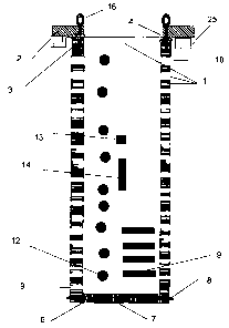
FIG. 1 is profile view of textile based debris trap.

CA 02530729 2005-12-28
FIG. 2 is plan view of top of the textile based debris trap.
DETAILED DESCRIPTION OF THE INVENTION
Referring to FIG. 1, a barrel based trap is illustrated. The body of the
barrel based trap is
a pipe (1) of known strength and radius. The pipe (1) has cut or drilled
openings
(9,12,13,14). The openings may be of any shape such as round (12), square
(13), slots
form horizontally (9), slots formed vertically (14). A bottom (7) is molded or
fitted into
the debris trap. If fitted the bottom is glued (6) and or mechanically
fastened (8) by
screws (8) to the pipe (1) forming the body of the trap or is cast or made as
part of the
pipe body (1). A support ring (2,24) is molded (24) onto the wall of the
barrel or the ring
(2) is glued (4) and or mechanically fastened (3) by screws (3) or other
fastener to the
pipe (1) and rests on the body of the well (25) or on a lower barrel support
ring (2) or
other structure (25). Below the bottom of the ring are holes (10) in the pipe
(1) adapted
to receive removal hooks (20,21). Removal eyes (16) are in some cases embedded
into
the support ring (2) and pipe (1) to allow the hooks or cables to be used to
remove the
debris trap.
Referring to Figure 2 one sees a plan view of the upper support ring (2) or
the continuous
molded net support (24). The upper support ring is connected to the pipe (1)
shown below
the support ring mechanically by glues and screws or bolts (3). The bottom
plate (7) of
the pipe (1) is shown. The holes (10) shown below the support ring adapted to
receive the
extraction hooks.
Referring to FIG.3 one sees the typical filter extraction hook consisting of
two parts
(20,2 1) with a hinge (11) holding the two hooks (20,2 1) together. An eye
(22) is attached
to the hinge so that it may receive hooks for extraction. A stud (18) is
affixed on one of
the hooks (21) to receive the locking bar (19), which bar has a slot (24) to
fit on the stud
(18) to provide a solid gap and connection. The locking bar (19) is hinged to
the hook
(21) by a loose bolt (17).
The invention as shown herein
Allows for the removal of debris from storm water streams where these are
discharged
from a road surface or other conveyance into an aquifer recharge well, which
well may or
may not contain filters. The barrel debris trap is of continuous length with
the receiving
body, having openings of maximum size along its length, so that as debris
fills the lower
reaches of the trap, water will flow out of the upper openings.
The body of the barrel trap is a pipe to make installation easier and to allow
sufficient
strength to carry the expected weights, static pressures, and flow forces..
The barrel debris traps can be removed when full or to gain access to the
lower body of
the well or filters below the debris traps.

CA 02530729 2005-12-28
The debris traps can be configured to fit inside each other to spread the
debris across
various size ranges.
Finally, the patent device is a patentable article, useful to commerce and the
environment,
and the process is patentable with the articles, and is useful to commerce.

Representative Drawing
A single figure which represents the drawing illustrating the invention.
Administrative Status

2024-08-01:As part of the Next Generation Patents (NGP) transition, the Canadian Patents Database (CPD) now contains a more detailed Event History, which replicates the Event Log of our new back-office solution.

Please note that "Inactive:" events refers to events no longer in use in our new back-office solution.

For a clearer understanding of the status of the application/patent presented on this page, the site Disclaimer , as well as the definitions for Patent , Event History , Maintenance Fee  and Payment History  should be consulted.

Event History

Description Date
Application Not Reinstated by Deadline 2010-12-29
Time Limit for Reversal Expired 2010-12-29
Inactive: Adhoc Request Documented 2010-09-30
Deemed Abandoned - Failure to Respond to Maintenance Fee Notice 2009-12-29
Application Published (Open to Public Inspection) 2007-06-28
Inactive: Cover page published 2007-06-27
Inactive: IPC assigned 2006-03-14
Inactive: First IPC assigned 2006-03-14
Inactive: IPC assigned 2006-03-12
Filing Requirements Determined Compliant 2006-01-31
Inactive: Office letter 2006-01-31
Inactive: Filing certificate - No RFE (English) 2006-01-31
Application Received - Regular National 2006-01-31
Small Entity Declaration Determined Compliant 2005-12-28

Abandonment History

Abandonment Date Reason Reinstatement Date
2009-12-29

Maintenance Fee

The last payment was received on 2008-12-29

Note : If the full payment has not been received on or before the date indicated, a further fee may be required which may be one of the following

  • the reinstatement fee;
  • the late payment fee; or
  • additional fee to reverse deemed expiry.

Please refer to the CIPO Patent Fees web page to see all current fee amounts.

Fee History

Fee Type Anniversary Year Due Date Paid Date
Application fee - small 2005-12-28
MF (application, 2nd anniv.) - small 02 2007-12-28 2007-12-19
MF (application, 3rd anniv.) - small 03 2008-12-29 2008-12-29
Owners on Record

Note: Records showing the ownership history in alphabetical order.

Current Owners on Record
JOHN VAN EGMOND
Past Owners on Record
None
Past Owners that do not appear in the "Owners on Record" listing will appear in other documentation within the application.
Documents

To view selected files, please enter reCAPTCHA code :


To view images, click a link in the Document Description column. To download the documents, select one or more checkboxes in the first column and then click the "Download Selected in PDF format (Zip Archive)" or the "Download Selected as Single PDF" button.

List of published and non-published patent-specific documents on the CPD .

If you have any difficulty accessing content, you can call the Client Service Centre at 1-866-997-1936 or send them an e-mail at CIPO Client Service Centre.


Document
Description 
Date
(yyyy-mm-dd) 
Number of pages   Size of Image (KB) 
Abstract 2005-12-28 1 22
Description 2005-12-28 4 152
Claims 2005-12-28 2 70
Representative drawing 2006-06-08 1 8
Cover Page 2007-06-20 2 43
Drawings 2005-12-28 5 501
Filing Certificate (English) 2006-01-31 1 158
Notice: Maintenance Fee Reminder 2007-10-01 1 130
Notice: Maintenance Fee Reminder 2008-09-30 1 120
Notice: Maintenance Fee Reminder 2009-09-29 1 119
Courtesy - Abandonment Letter (Maintenance Fee) 2010-02-23 1 172
Second Notice: Maintenance Fee Reminder 2010-06-29 1 120
Reminder - Request for Examination 2010-08-31 1 121
Notice: Maintenance Fee Reminder 2010-09-29 1 121
Correspondence 2006-01-31 1 13