Sélection de la langue

Search

Sommaire du brevet 2530729 

Énoncé de désistement de responsabilité concernant l'information provenant de tiers

Une partie des informations de ce site Web a été fournie par des sources externes. Le gouvernement du Canada n'assume aucune responsabilité concernant la précision, l'actualité ou la fiabilité des informations fournies par les sources externes. Les utilisateurs qui désirent employer cette information devraient consulter directement la source des informations. Le contenu fourni par les sources externes n'est pas assujetti aux exigences sur les langues officielles, la protection des renseignements personnels et l'accessibilité.

Disponibilité de l'Abrégé et des Revendications

L'apparition de différences dans le texte et l'image des Revendications et de l'Abrégé dépend du moment auquel le document est publié. Les textes des Revendications et de l'Abrégé sont affichés :

  • lorsque la demande peut être examinée par le public;
  • lorsque le brevet est émis (délivrance).
(12) Demande de brevet: (11) CA 2530729
(54) Titre français: GRILLE A DEBRIS EN TAMBOUR
(54) Titre anglais: BARREL DEBRIS TRAP
Statut: Réputée abandonnée et au-delà du délai pour le rétablissement - en attente de la réponse à l’avis de communication rejetée
Données bibliographiques
Abrégés

Abrégé anglais


A system of deep well barrel debris traps for storm water polishing before
discharge to
groundwater recharge wells is disclosed herein. The debris trap is formed by
one or more
traps, which can fill up relatively in sequence. The debris trap captures
coarse sediment
and leaves which enter into the well portion of wells and aquifer recharge
wells. The
traps are designed to capture debris and sediment such as leaves, gravel, and
other large
debris which would plug filters or aquifer formations. By building the traps
in series
these can capture the entire stream flow, each can fill up individually and
when full, can
continue to allow substantial flows of water past the individual trap. When
used in
conjunction with Storm Water Infiltration wells and aquifer recharge wells the
debris
trap can extent the time between maintenance cycles, increase the time to full
cake
formation plugging of filters or the aquifer formation.

Revendications

Note : Les revendications sont présentées dans la langue officielle dans laquelle elles ont été soumises.


Claims
1. A barrel type debris trap, with cut or drilled opening sizes designed to
capture large
debris and sediment, but not finer sediments, dissolved solids, or other fine
suspended
solids comprising:
a barrel shaped trap with a diameter that does not fill the annulus of a well
or other
debris trap.
a barrel shaped trap of solid metal or plastic type material, or metal or
plastic strand,
with horizontal, vertical, or drilled openings in the side walls whose
openings are
sized to capture mainly debris such as leaves, gravel, human made debris.
a barrel shaped trap whose side wall openings are enough to allow water and
undersized materials to pass, but which are not so numerous as to weaken the
pipe so
that it can not carry the required loads due to weight, static water pressure,
and
flowing water.
an insertion and extraction rope or handle to allow a new trap to be installed
into a
well or to allow it to be removed, and so that smaller diameter traps can be
installed
through the top to the unit.
an upper support ring able to carry the weight and water forces onto the top
of the
well body or other support platform.
a lower sealing plate at the bottom of the barrel to prevent flow of debris
into the well
or lower units.
a surface support ring allowing successively smaller debris traps to fit
inside traps
with smaller net openings.
2. A debris barrel trap, when made with barrels of smaller size, which can be
nested to
save shipping space.
3. A debris barrel traps, when made of solid metal or metal strand or strong
material such
as metal plastics, which can be formed into a slight conical shape to
facilitate shipping
and when different size opening sizes are made, which can conformably be
nested while
leaving a gap between the debris traps.
4. A funnel structure to divert all of the flow reaching the well unit into
the top of the
barrel debris trap.

5. A connector or connectors, at the top of the well, adapted to receive the
support cables,
removal handle, and connectors from the debris barrel trap.
6. A connector or connectors to support the sum of the weight of the sediment
trap when
full and the forces due to the flow of the water when flowing. The connect
ring can be
removed as needed, but when the trap is full carries a heavy load.
7. A barrel debris trap structure wherein the funnel is set at the top of the
well or on a
support lip, bracket or bolts.
8. A barrel debris trap structure where each trap being of a maximum size and
diameter
so that when the trap is full water with debris can still bypass the trap to
reach the filters
or infiltration units below.
9. A structure where a handle is on the top of unit which fits into adapted
openings in the
connector ring so the individual debris traps may be removed.
10. A structure or series of structures which can remove all particles above a
given size,
or which can remove particles in a series of size ranges, each with a given
minimum size.
11. A structure which may be adapted to fit inside a storm water drain system
component.

Description

Note : Les descriptions sont présentées dans la langue officielle dans laquelle elles ont été soumises.

CA 02530729 2005-12-28
TECHNICAL FIELD
This invention relates to debris traps for removing the larger debris such as
leaves, gravel,
pop cans, paper from water streams being diverted into wells or receiving
chambers.
BACKGROUND OF THE INVENTION
In storm water diversion into recharge wells, debris such as leaves, gravel,
paper, grass,
trees, metal parts, and other natural and human made can flow into channels,
gutters,
drains, and the like, eventually finding their way into the body of the well.
Modern wells
have filters. The filters catch the debris on the surface and the debris forms
a layer or
cake which can reduce the flow of water through the filters. Conventionally
debris is
often not capture at all, or is captured by add on passive or centrifugal type
units, or by
means of sediment ponds, straw bales, or by means of full surface sediment
screens or
cloths, and the like. In the former case, large units are supplied in the
storm channel and
land must be set aside to house the units. In the case of Geotextiles or other
screen
material the debris quickly fills the screen pore openings. The screens are
set under the
catchbasin lid or in the horizontal outlet from the catchbasin. In the case of
sediment
capture trays, the trays overflow in large events not trapping all of the
debris. The barrel
trap allows continuous capture of debris till full, the extent of capture
depending on the
length and diameter of the well, and not on only on the surface of the
catchbasis or well
surface. Other debris traps that are based on textile nets are available.
DISCLOSURE OF INVENTION
I have come to the realization that debris can be a major impact on recharge
wells,
including filtered recharge wells. Many recharge wells without have to be
redrilled
periodically. Filtered wells need more frequent maintenance because of debris.
A
structure is provided herein from capturing debris from the storm water before
it is
directly discharged into a recharge well or into a filtered recharge well.
A series of barrel shaped debris traps is disclosed to extend the time between
aquifer
recharge well reconstruction or for removing filters between maintenance
cycles. The
Barrel debris traps, are designed to be of limited size and diameter when
"full" so that
flow can be maintained past the debris trap. The debris trap can be removed.
The debris
trap includes the trap and its supporting elements.
The barrel type debris trap is characterized by a body of restricted diameter
so that even
when full, water may flow past a given debris trap for capture on other debris
traps in

CA 02530729 2005-12-28
series. The debris trap is also characterized by a chute or chutes s to direct
water at all
times towards the unfilled portion of a debris trap.
Aquifer recharge techologies are becoming more common and more accepted. A
problem
with recharge wells is the accu.mulation of debris and sediment in the body of
the well
and in the cases of unfiltered wells, plugging of the formation around the
well.
Further, there are sediment traps such as ponds which require large tracts of
lands,
horizontal pipes without filters, centrifugal sediment trapping technologies
which fit in
series with systems for recharge, and catchbasin inserts.
The structure disclosed herein can be used instead of or as an add on
technology. For
example when used instead of a sediment pond, a builder can use the land
formerly set
aside for ponds to build green space, more houses, and to protect the public
from debris
and flows.
STATEMENT AS TO RIGHTS TO INVENTIONS MADE UNDER
BRIEF DESCRIPTION OF THE DRAWINGS
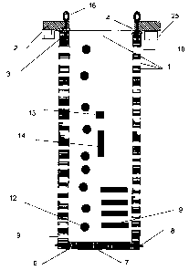
FIG. 1 is profile view of textile based debris trap.

CA 02530729 2005-12-28
FIG. 2 is plan view of top of the textile based debris trap.
DETAILED DESCRIPTION OF THE INVENTION
Referring to FIG. 1, a barrel based trap is illustrated. The body of the
barrel based trap is
a pipe (1) of known strength and radius. The pipe (1) has cut or drilled
openings
(9,12,13,14). The openings may be of any shape such as round (12), square
(13), slots
form horizontally (9), slots formed vertically (14). A bottom (7) is molded or
fitted into
the debris trap. If fitted the bottom is glued (6) and or mechanically
fastened (8) by
screws (8) to the pipe (1) forming the body of the trap or is cast or made as
part of the
pipe body (1). A support ring (2,24) is molded (24) onto the wall of the
barrel or the ring
(2) is glued (4) and or mechanically fastened (3) by screws (3) or other
fastener to the
pipe (1) and rests on the body of the well (25) or on a lower barrel support
ring (2) or
other structure (25). Below the bottom of the ring are holes (10) in the pipe
(1) adapted
to receive removal hooks (20,21). Removal eyes (16) are in some cases embedded
into
the support ring (2) and pipe (1) to allow the hooks or cables to be used to
remove the
debris trap.
Referring to Figure 2 one sees a plan view of the upper support ring (2) or
the continuous
molded net support (24). The upper support ring is connected to the pipe (1)
shown below
the support ring mechanically by glues and screws or bolts (3). The bottom
plate (7) of
the pipe (1) is shown. The holes (10) shown below the support ring adapted to
receive the
extraction hooks.
Referring to FIG.3 one sees the typical filter extraction hook consisting of
two parts
(20,2 1) with a hinge (11) holding the two hooks (20,2 1) together. An eye
(22) is attached
to the hinge so that it may receive hooks for extraction. A stud (18) is
affixed on one of
the hooks (21) to receive the locking bar (19), which bar has a slot (24) to
fit on the stud
(18) to provide a solid gap and connection. The locking bar (19) is hinged to
the hook
(21) by a loose bolt (17).
The invention as shown herein
Allows for the removal of debris from storm water streams where these are
discharged
from a road surface or other conveyance into an aquifer recharge well, which
well may or
may not contain filters. The barrel debris trap is of continuous length with
the receiving
body, having openings of maximum size along its length, so that as debris
fills the lower
reaches of the trap, water will flow out of the upper openings.
The body of the barrel trap is a pipe to make installation easier and to allow
sufficient
strength to carry the expected weights, static pressures, and flow forces..
The barrel debris traps can be removed when full or to gain access to the
lower body of
the well or filters below the debris traps.

CA 02530729 2005-12-28
The debris traps can be configured to fit inside each other to spread the
debris across
various size ranges.
Finally, the patent device is a patentable article, useful to commerce and the
environment,
and the process is patentable with the articles, and is useful to commerce.

Dessin représentatif
Une figure unique qui représente un dessin illustrant l'invention.
États administratifs

2024-08-01 : Dans le cadre de la transition vers les Brevets de nouvelle génération (BNG), la base de données sur les brevets canadiens (BDBC) contient désormais un Historique d'événement plus détaillé, qui reproduit le Journal des événements de notre nouvelle solution interne.

Veuillez noter que les événements débutant par « Inactive : » se réfèrent à des événements qui ne sont plus utilisés dans notre nouvelle solution interne.

Pour une meilleure compréhension de l'état de la demande ou brevet qui figure sur cette page, la rubrique Mise en garde , et les descriptions de Brevet , Historique d'événement , Taxes périodiques et Historique des paiements devraient être consultées.

Historique d'événement

Description Date
Demande non rétablie avant l'échéance 2010-12-29
Le délai pour l'annulation est expiré 2010-12-29
Inactive : Demande ad hoc documentée 2010-09-30
Réputée abandonnée - omission de répondre à un avis sur les taxes pour le maintien en état 2009-12-29
Demande publiée (accessible au public) 2007-06-28
Inactive : Page couverture publiée 2007-06-27
Inactive : CIB attribuée 2006-03-14
Inactive : CIB en 1re position 2006-03-14
Inactive : CIB attribuée 2006-03-12
Exigences de dépôt - jugé conforme 2006-01-31
Inactive : Lettre officielle 2006-01-31
Inactive : Certificat de dépôt - Sans RE (Anglais) 2006-01-31
Demande reçue - nationale ordinaire 2006-01-31
Déclaration du statut de petite entité jugée conforme 2005-12-28

Historique d'abandonnement

Date d'abandonnement Raison Date de rétablissement
2009-12-29

Taxes périodiques

Le dernier paiement a été reçu le 2008-12-29

Avis : Si le paiement en totalité n'a pas été reçu au plus tard à la date indiquée, une taxe supplémentaire peut être imposée, soit une des taxes suivantes :

  • taxe de rétablissement ;
  • taxe pour paiement en souffrance ; ou
  • taxe additionnelle pour le renversement d'une péremption réputée.

Veuillez vous référer à la page web des taxes sur les brevets de l'OPIC pour voir tous les montants actuels des taxes.

Historique des taxes

Type de taxes Anniversaire Échéance Date payée
Taxe pour le dépôt - petite 2005-12-28
TM (demande, 2e anniv.) - petite 02 2007-12-28 2007-12-19
TM (demande, 3e anniv.) - petite 03 2008-12-29 2008-12-29
Titulaires au dossier

Les titulaires actuels et antérieures au dossier sont affichés en ordre alphabétique.

Titulaires actuels au dossier
JOHN VAN EGMOND
Titulaires antérieures au dossier
S.O.
Les propriétaires antérieurs qui ne figurent pas dans la liste des « Propriétaires au dossier » apparaîtront dans d'autres documents au dossier.
Documents

Pour visionner les fichiers sélectionnés, entrer le code reCAPTCHA :


Pour visualiser une image, cliquer sur un lien dans la colonne description du document. Pour télécharger l'image (les images), cliquer l'une ou plusieurs cases à cocher dans la première colonne et ensuite cliquer sur le bouton "Télécharger sélection en format PDF (archive Zip)" ou le bouton "Télécharger sélection (en un fichier PDF fusionné)".

Liste des documents de brevet publiés et non publiés sur la BDBC .

Si vous avez des difficultés à accéder au contenu, veuillez communiquer avec le Centre de services à la clientèle au 1-866-997-1936, ou envoyer un courriel au Centre de service à la clientèle de l'OPIC.


Description du
Document 
Date
(aaaa-mm-jj) 
Nombre de pages   Taille de l'image (Ko) 
Abrégé 2005-12-28 1 22
Description 2005-12-28 4 152
Revendications 2005-12-28 2 70
Dessin représentatif 2006-06-08 1 8
Page couverture 2007-06-20 2 43
Dessins 2005-12-28 5 501
Certificat de dépôt (anglais) 2006-01-31 1 158
Avis de rappel: Taxes de maintien 2007-10-01 1 130
Avis de rappel: Taxes de maintien 2008-09-30 1 120
Avis de rappel: Taxes de maintien 2009-09-29 1 119
Courtoisie - Lettre d'abandon (taxe de maintien en état) 2010-02-23 1 172
Deuxième avis de rappel: taxes de maintien 2010-06-29 1 120
Rappel - requête d'examen 2010-08-31 1 121
Avis de rappel: Taxes de maintien 2010-09-29 1 121
Correspondance 2006-01-31 1 13