Language selection

Search

Patent 2530829 Summary

Third-party information liability

Some of the information on this Web page has been provided by external sources. The Government of Canada is not responsible for the accuracy, reliability or currency of the information supplied by external sources. Users wishing to rely upon this information should consult directly with the source of the information. Content provided by external sources is not subject to official languages, privacy and accessibility requirements.

Claims and Abstract availability

Any discrepancies in the text and image of the Claims and Abstract are due to differing posting times. Text of the Claims and Abstract are posted:

  • At the time the application is open to public inspection;
  • At the time of issue of the patent (grant).
(12) Patent: (11) CA 2530829
(54) English Title: METAL TO PLASTIC FLUID CONNECTION WITH OVERMOLDED ANTI-ROTATION RETAINER
(54) French Title: CONNEXION FLUIDIQUE METAL SUR PLASTIQUE MUNIE D'UN DISPOSITIF ANTIROTATION SURMOULE
Status: Deemed expired
Bibliographic Data
(51) International Patent Classification (IPC):
  • F16L 47/00 (2006.01)
  • F16L 13/00 (2006.01)
(72) Inventors :
  • SLUNICK, STEVEN (United States of America)
  • KANE, NORMAN F. (United States of America)
(73) Owners :
  • COOPER-STANDARD AUTOMOTIVE INC. (United States of America)
(71) Applicants :
  • COOPER-STANDARD AUTOMOTIVE INC. (United States of America)
(74) Agent: GOWLING WLG (CANADA) LLP
(74) Associate agent:
(45) Issued: 2012-03-20
(86) PCT Filing Date: 2004-08-18
(87) Open to Public Inspection: 2005-03-10
Examination requested: 2009-07-03
Availability of licence: N/A
(25) Language of filing: English

Patent Cooperation Treaty (PCT): Yes
(86) PCT Filing Number: PCT/US2004/026852
(87) International Publication Number: WO2005/022022
(85) National Entry: 2005-12-29

(30) Application Priority Data:
Application No. Country/Territory Date
60/497,199 United States of America 2003-08-21

Abstracts

English Abstract


A fluid connection assembly (10) includes a metal tube (22) having a flared
end and a plastic manifold (12) having a port (14). The port (14) includes an
annular collar (16) and an annular recess (18) that receives a seal (20). The
metal tube (22) is arranged over the port (14) and engages the seal (20). The
flared end of the metal tube (22) abuts the annular collar (16) of the port
(14) when the metal tube (22) is installed. A plastic retainer (28) is molded
over the annular collar (16) of the port (14) and the flared end of the metal
tube (22) to retain the metal tube (22) axially on the port (14) of the
manifold (12). Alternately, the end (221) of the metal tube (222) is crimped
to secure the metal tube (222) to the port (214) of the manifold (212).


French Abstract

L'invention concerne un ensemble connexion fluidique (10) qui comprend un tube métallique (22) pourvu d'un bout évasé et d'un collecteur plastique (12) comportant un orifice (14). L'orifice (14) comprend un manchon annulaire (16) et un évidement annulaire (18) qui reçoit un joint (20). Le tube métallique (22) est installé sur l'orifice (14) et vient en contact avec le joint (20). Le bout évasé du tube métallique (22) s'aligne bout à bout avec le manchon annulaire (16) de l'orifice (14) lorsque le tube métallique (22) est installé. Un dispositif de retenue en plastique (28) est moulé par-dessus le manchon annulaire (16) de l'orifice (14) et le bout évasé du tube métallique (22) afin de retenir le tube métallique (22) axialement sur l'orifice (14) du collecteur (12). Dans une variante, l'extrémité (221) du tube métallique (222) est serti de façon à fixer le tube métallique (222) sur l'orifice (214) du collecteur (212).

Claims

Note: Claims are shown in the official language in which they were submitted.


What is claimed is:


1. A fluid connection assembly comprising:
a housing including a fluid port, the fluid port of the housing including a
first
notch, and the housing is made of a first material;
a tube made of a second material dissimilar to the first material, wherein the
tube
includes a second notch;
a seal located between the tube and the fluid port; and
a retainer to secure the fluid port to the tube
wherein the first notch and the second notch prevent relative rotation between
the
fluid port of the housing and the tube, and a portion of the retainer is
received in the first
notchand the second notch to prevent relative rotation between the fluid port
of the
housing and the tube.


2. The assembly as recited in claim 1 wherein the first material is plastic
and the
second material is metal.


3. The assembly as recited in claim 1 wherein the housing is a manifold.

4. The assembly as recited in claim 1 wherein the tube is aluminum.


5. The assembly as recited in claim 1 wherein the retainer is plastic.


6. The assembly as recited in claim 1 wherein the fluid port is inserted into
the tube,
the fluid port includes an annular collar, and the tube includes a flared end
that abuts the
annular collar.


7. The assembly as recited in claim 6 wherein the retainer is molded over the
annular
collar of the fluid port and the flared end of the tube.


8. The assembly as recited in claim 1 wherein the fluid port includes at least
one

-6-


annular recess that receives the seal.


9. The assembly as recited in claim 1 wherein the tube is inserted into the
fluid port,
the fluid port includes a flared end and the metal tube includes an annular
collar, and the
annular collar of the metal tube abuts the flared end of the fluid port.


10. The assembly as recited in claim I wherein the tube includes an end having
a first
inner diameter that is arranged over the fluid port, and the end of the tube
is crimped by a
crimping tool to have a second diameter that is less than the first diameter.


11. The assembly as recited in claim 1 wherein the tube is inserted into the
fluid port
at a joint compressing the seal therebetween, and the retainer is overmolded
the joint.


12. A fluid connection assembly comprising:
a plastic manifold including a fluid port, and the fluid port includes an
annular
collar and an annular recess, whereinthe fluid port of the plastic manifold
includes a first
notch;
a metal tube including a flared end, and the flared end abuts the annular
collar of
the fluid port, wherein the metal tube includes a second notch;
a seal received in the annular recess of the fluid port, and the seal is
located
between the metal tube and the fluid port;
a plastic retainer molded over the annular collar and the flared end to secure
the
fluid port to the metal tube,
wherein the first notch and the second notch prevent relative rotation between
the
fluid port of the housing and the tube, and a portion of the plastic retainer
is received in
the first notchand the second notch to prevent relative rotation between the
fluid port of
the housing and the tube.


13. A method of assembling a fluid connection comprising the step of-
attaching a fluid port of a plastic housing to a metal tube, whereinthe fluid
port of
the plastic manifold includes a first notch and the metal tube includes a
second notch;


-7-


locating a seal between the metal tube and the fluid port;
retaining the fluid port to the metal tube with a retainer made of a material;
and
preventing rotation between the fluid port of the plastic housing and the
metal
tube by flowing the material of the plastic housing into the first notch and
the second
notch such that a portion of the retainer is received in the first notchand
the second notch.
14. The method as recited in claim 13 further including the step of inserting
the fluid
port into the metal tube.

15. The method as recited in claim 14 further including the step of preventing
over
insertion of the metal tube during the step of inserting the fluid port into
the metal tube.
16. The method as recited in claim 13 wherein the step of retaining includes
crimping
an end of the metal tube to secure the metal tube relative to the fluid port.

17. The assembly as recited in claim 1 wherein the first notchof the fluid
port is
formed on an annular collar of said fluid port, and thesecond notchof the tube
is formed
on a flared end of said tube.

18. The assembly as recited in claim 1 wherein the first notch of the fluid
port of the
housing comprises two diametrically opposed notches and the second notch of
the tube
comprises two diametrically opposed notches.

19. The assembly as recited in claim 12 wherein the first notch of the fluid
port is
formed on the annular collar of said fluid port, and the second notch of the
tube is formed
on the flared end of said tube.

20. The assembly as recited in claim 12 wherein the first notch of the fluid
port of the
plastic manifold comprises two diametrically opposed notches and the second
notch of
the tube comprises two diametrically opposed notches.

-8-

Description

Note: Descriptions are shown in the official language in which they were submitted.


CA 02530829 2005-12-29
WO 2005/022022 PCT/US2004/026852
METAL TO PLASTIC FLUID CONNECTION WITH
OVERMOLDED ANTI-ROTATION RETAINER
BACKGROUND OF THE INVENTION
The present invention relates generally to a fluid connection assembly
including a metal tube and a plastic housing secured together by a retainer
and a
method of making the fluid connection assembly.
Numerous fluid connections are used in the art. One type of fluid connection
secures a metal tube to a fluid housing. In some applications, the fluid
housing is a
metal block referred to as a braze block. The metal tube is secured to the
fluid housing
by brazing. It is advantageous to secure the metal tube to the fluid housing
so that the
metal tube is in the desired position relative to the fluid housing during
shipping and
installation. However, there are several drawbacks to brazing. For one,
brazing is
expensive and relatively difficult to control. Additionally, if a non-uniform
braze bead
is formed, leaks may occur between the metal tube and the fluid housing.
Moreover,
the braze block is relatively heavy.
Therefore, there is a need for a fluid connection assembly that provides an
improved fluid connection that connects dissimilar materials, reduces the cost
of the
prior art assembly, reduces the potential for leaks, and overcomes the
drawbacks and
the shortcomings of the prior art.
SUIVEV1ARY OF THE INVENTION
A fluid connection assembly includes a metal tube having a flared end and a
plastic manifold having a port. The port includes an annular collar and an
annular
recess that receives a seal. The metal tube is arranged over the port and
engages the
seal. When the metal tube is arranged over the port, the flared end abuts the
annular
collar of the port. Once the metal tube is installed on the port of the
manifold, a
plastic retainer is molded over the annular collar of the port and the flared
end of the
metal tube to retain the metal tube axially on the port of the manifold. The
material
of the retainer enters a locating feature on the port and the metal tube to
prevent
rotation of the metal tube relative to the manifold.
-1-


CA 02530829 2005-12-29
WO 2005/022022 PCT/US2004/026852
Alternately, the port includes a flared end and the metal tube includes an
annular collar. The metal tube is inserted into the port, and the annular
collar of the
metal tube engages the flared end of the port to prevent over insertion of the
metal
tube into the port. A seal is received in a recess in the metal tube. When the
metal
tube is inserted into the port, the seal is located between the metal tube and
the port.
A retainer is molded over the annular collar of the metal tube and the flared
end of
the port to retain the metal tube axially on the port of the manifold.
In another embodiment, the metal tube is positioned over the port and the end
is crimped to secure the metal tube to the port of the manifold.
In another embodiment, the port of the manifold includes a flared end. A
metal tube is inserted into the flared end of the port, compressing a seal
between the
port and the metal tube. A retainer is over-molded over the joint of the port
and the
metal tube, compressing the seal and retaining the components together.
These and other features of the present invention will be best understood
from the following specification and drawings.
BRIEF DESCRIPTION OF THE DRAWINGS
The various features and advantages of the invention will become apparent to
those skilled in the art from the following detailed description of the
currently
preferred embodiment. The drawings that accompany the detailed description can
be
briefly described as follows:
Figure 1 illustrates a cross-sectional view of the fluid connection assembly
of
the present invention;
Figure 2 illustrates a perspective view of the fluid connection assembly with
a tube installed onto a port of a manifold;
Figure 3 illustrates a cross-sectional view of a second embodiment of the
fluid connection assembly of the present invention;
Figure 4 illustrates a cross-sectional view of a third embodiment of the fluid
connection assembly of the present invention; and
Figure 5 illustrates a cross-sectional view of a fourth embodiment of the
fluid
connection assembly of the present invention.
-2-


CA 02530829 2005-12-29
WO 2005/022022 PCT/US2004/026852
DETAILED DESCRIPTION OF THE PREFERRED EMBODIMENT
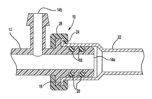
Figures 1 and 2 illustrate a fluid connection assembly 10 including a housing
having one or more ports 14a and 14b. In one embodiment, the housing is a
manifold 12. The manifold 12 may be constructed from any suitable lightweight
material, but preferably the manifold 12 is constructed from plastic to reduce
the
weight of the fluid connection assembly 10. In one example, the manifold 12 is
made of nylon. As will be appreciated from the description below, a metal
block is
not necessary because the brazing operation of the prior art is eliminated.
The fluid connection assembly 10 can be utilized in any fluid conveying
system through which fluid travels, including vapor or liquid. The fluid
connection
assembly 10 can be used in a water heater system, an air conditioning
system,'or a
hydraulic system. Although these examples are described, it is to be
understood that
the fluid connection assembly 10 can be used in any fluid conveying system.
The port 14a includes an annular collar 16 that acts as a stop. The port 14a
also includes one or more annular recesses 18 that are spaced from the annular
collar
16. Each annular recess 18 receives a seal 20, such as a rubber O-ring, that
provides
a leak proof assembly. A metal tube 22 is arranged over the port 14a and
engages
the seals 20. The metal tube 22 includes a flared end 24 that abuts the
annular collar
16 when the metal tube 22 is fully installed. The metal tube 22 can be
aluminum or
steel. However, the tube 22 can be made of other materials, and one skilled in
the
art would know what materials to employ. The present invention enables the
plastic
manifold 12 and the metal tube 22, which are made of dissimilar materials, to
be
joined by forming a leak proof fluid connection.
The port 14a and the metal tube 22 each include a locating feature 30 and 26,
respectively, as will be better appreciated from the description below.
Preferably,
the annular collar 16 of the port 14a and the flared end 24 of the metal tube
22 both
include the locating feature 30 and 26, respectively. Preferably, the locating
features
26 and 30 are notches.
When the metal tube 22 is installed on the port 14a of the manifold 12, a
retainer 28 is molded over the annular collar 16 of the port 14a and the
flared end 24
of the metal tube 22 to retain the metal tube 22 axially on the port 14a. In
one
-3-


CA 02530829 2005-12-29
WO 2005/022022 PCT/US2004/026852
example, the retainer 28 is plastic. Preferably, the retainer 28 is injection
molded. A
mold is positioned over the joint of the metal tube 22 and the port 14a of the
manifold 12. The melted material of the retainer 28 enters the mold and flows
into
the locating features 26 and 30. After the melted material cools, the mold is
removed, providing the retainer 28. The retainer 28 rotationally locks the
metal tube
22 to the port 14a of the manifold 12 and prevents relative rotation between
the
metal tube 22 and the port 14a.
Alternately, as shown in Figure 3, a metal tube 122 is inserted into a port
114
of a manifold 112. The port 114 includes a flared end 124, and the metal tube
122
includes an annular collar 116. When the metal tube 122 is inserted into the
port
114, the flared end 124 of the port 114 engages the annular collar 116 of the
metal
tube 122 to prevent over insertion of the metal tube 122 into the port 114.
The metal
tube 122 includes a recess 118 spaced from the annular collar 116, and a seal
120 is
received in the recess 118. When the metal tube 122 is inserted into the port
114 of
the manifold 112, the seal 120 is located between the metal tube 122 and the
port
114. A retainer 128 is molded over the annular collar 116 of the metal tube
122 and
the flared end 124 of the port 114 to retain the metal tube 122 axially on the
port
114. Although not illustrated, the metal tube 122 and the port 114 of the
manifold
112 each include locating features to prevent relative rotation of the metal
tube 122
relative to the port 114.
Figure 4 illustrates a third embodiment of a fluid connection assembly 210
including a manifold 212 having port 214. The port 214 includes two annular
collars 216a and 216b and an annular recess 218 located between the two
annular
collars 216a and 216b. Each of the two annular collars 216a and 216b has an
outer
diameter D3. The annular recess 218 receives a seal 220. In one example, the
seal
220 is a rubber O-ring. A metal tube 222 is arranged over the port 214 and
engages
the seal 220. The port 214 andlor the metal tube 222 can also include a
locating
feature 226 that positions the metal tube 222 relative to the port 114 of the
manifold
212.
When the metal tube 222 is installed, the end 221 of the metal tube 222 is
arranged over the port 214, as shown by the dotted line. The end 221 has an
inner
-4-


CA 02530829 2005-12-29
WO 2005/022022 PCT/US2004/026852
diameter D1. The inner diameter D1 of the end 221 of the metal tube 222 is
slightly
greater than the outer diameter D3 of the two annular collars 216a and 216b.
The
end 221 of the metal tube 222 is then crimped to secure the end 221 of the
metal
tube 222 on the port 214 of the manifold 212, as shown by the solid line. When
crimped, the end 221 of the metal tube 222 has an inner diameter D2, which is
less
than the inner diameter D1. The end 221 of the metal tube 222 can be crimped
by an
8 jaw. However, other tools can be used to crimp the end 221 of the metal tube
222,
and one skilled in the art would know how to crimp the end 221 of the metal
tube
222.
Figure 5 illustrates a fourth embodiment of a fluid connection assembly 310
including a manifold 312 having port 314. The port 314 includes a flared end
321.
A metal tube 322 is inserted into the port 314, compressing a seal 320 between
the
flared end 321 of the port 314 and the metal tube 322. A retainer 326 is over-
molded over the joint of the port 314 of the manifold 312 and the metal tube
322.
The retainer 326 compresses the seal 320 and retains the components together.
Alternately, the metal tube 322 includes the flared end and the port 314 is
inserted
into the metal tube 322.
The foregoing description is only exemplary of the principles of the
invention. Many modifications and variations are possible in light of the
above
teachings. It is, therefore, to be understood that within the scope of the
appended
claims, the invention may be practiced otherwise than using the example
embodiments which have been specifically described. For that reason the
following
claims should be studied to determine the true scope and content of this
invention.
-5-

Representative Drawing
A single figure which represents the drawing illustrating the invention.
Administrative Status

For a clearer understanding of the status of the application/patent presented on this page, the site Disclaimer , as well as the definitions for Patent , Administrative Status , Maintenance Fee  and Payment History  should be consulted.

Administrative Status

Title Date
Forecasted Issue Date 2012-03-20
(86) PCT Filing Date 2004-08-18
(87) PCT Publication Date 2005-03-10
(85) National Entry 2005-12-29
Examination Requested 2009-07-03
(45) Issued 2012-03-20
Deemed Expired 2021-08-18

Abandonment History

There is no abandonment history.

Payment History

Fee Type Anniversary Year Due Date Amount Paid Paid Date
Registration of a document - section 124 $100.00 2005-12-29
Application Fee $400.00 2005-12-29
Maintenance Fee - Application - New Act 2 2006-08-18 $100.00 2006-08-03
Maintenance Fee - Application - New Act 3 2007-08-20 $100.00 2007-08-03
Maintenance Fee - Application - New Act 4 2008-08-18 $100.00 2008-08-08
Request for Examination $800.00 2009-07-03
Maintenance Fee - Application - New Act 5 2009-08-18 $200.00 2009-07-31
Maintenance Fee - Application - New Act 6 2010-08-18 $200.00 2010-07-28
Maintenance Fee - Application - New Act 7 2011-08-18 $200.00 2011-07-18
Final Fee $300.00 2012-01-03
Maintenance Fee - Patent - New Act 8 2012-08-20 $200.00 2012-07-19
Maintenance Fee - Patent - New Act 9 2013-08-19 $200.00 2013-07-12
Maintenance Fee - Patent - New Act 10 2014-08-18 $250.00 2014-07-24
Maintenance Fee - Patent - New Act 11 2015-08-18 $250.00 2015-07-29
Maintenance Fee - Patent - New Act 12 2016-08-18 $250.00 2016-07-27
Maintenance Fee - Patent - New Act 13 2017-08-18 $250.00 2017-08-14
Maintenance Fee - Patent - New Act 14 2018-08-20 $250.00 2018-08-13
Maintenance Fee - Patent - New Act 15 2019-08-19 $450.00 2019-08-09
Maintenance Fee - Patent - New Act 16 2020-08-18 $450.00 2020-08-21
Owners on Record

Note: Records showing the ownership history in alphabetical order.

Current Owners on Record
COOPER-STANDARD AUTOMOTIVE INC.
Past Owners on Record
KANE, NORMAN F.
SLUNICK, STEVEN
Past Owners that do not appear in the "Owners on Record" listing will appear in other documentation within the application.
Documents

To view selected files, please enter reCAPTCHA code :


To view images, click a link in the Document Description column. To download the documents, select one or more checkboxes in the first column and then click the "Download Selected in PDF format (Zip Archive)" or the "Download Selected as Single PDF" button.

List of published and non-published patent-specific documents on the CPD .

If you have any difficulty accessing content, you can call the Client Service Centre at 1-866-997-1936 or send them an e-mail at CIPO Client Service Centre.


Document
Description 
Date
(yyyy-mm-dd) 
Number of pages   Size of Image (KB) 
Description 2005-12-29 5 262
Representative Drawing 2005-12-29 1 21
Claims 2005-12-29 3 100
Abstract 2005-12-29 2 78
Drawings 2005-12-29 2 67
Cover Page 2006-03-02 1 56
Claims 2011-07-07 3 113
Claims 2011-10-24 3 119
Representative Drawing 2012-02-22 1 21
Cover Page 2012-02-22 1 56
Assignment 2005-12-29 2 76
PCT 2005-12-29 6 199
Correspondence 2006-02-27 1 28
Assignment 2006-12-12 8 283
Correspondence 2006-12-12 6 155
Assignment 2007-01-08 1 28
Prosecution-Amendment 2009-07-03 2 50
Assignment 2005-12-29 3 116
Prosecution-Amendment 2011-08-15 3 118
Prosecution-Amendment 2011-01-24 3 115
Prosecution-Amendment 2011-07-07 6 221
Prosecution-Amendment 2011-10-24 5 199
Correspondence 2012-01-03 2 50