Note: Descriptions are shown in the official language in which they were submitted.
CA 02530924 2005-12-20
- 1 -
TITLE OF THE INVENTION
IP TELEPHONE SYSTEM '
BACKGROUND OF THE INVENTION
The present invention relates to an Internet
5 protocol (IP) telephone system for make a communication
via an IP network (for example, the Internet).
An Internet telephone (hereinafter, referred to as
IP telephone) to make a communication via the IP
network has been known. The IP telephone system has an
10 server to perform communication control among IP
telephone terminals. Additional providing of a
registrar server to manage user IDs and the IP
telephone terminals causes a possibility of
communications by using the same user ID from any where
15 through the IP telephone terminals connected to the IP
network.
In the system performing such communication
control, the burden of a server to manage IP addresses
and the user IDs of the IP telephone terminals becomes
20 heavy with the increase of the number of the IP
telephone terminals. Since an IP address resource is
finite, a method for effectively utilizing an address
resource by converting a global address into a local
address has been introduced [for example, refer to Jpn.
25 Pat. Appln. KOKAI publication No. 11-122285 (page
fourteenth, FIG. 1)].
Although this method is effective to save the IP
CA 02530924 2005-12-20
- 2 -
address resource, this method cannot realize an ID
management function to manage a large number of IP
telephone terminals by using the same user ID.
Accordingly, in the case of a large number of IP
S telephone terminals, the processing load related to the
server to manage the IP addresses and the user IDs of
the IP telephone terminals are still large.
BRIEF SUMMARY OF THE INVENTION
The IP telephone system makes it possible for IP
10 telephone terminals to make telephone calls from any
where through an IP network by using the same user ID.
However, this system has the problem such that a Load
of the server becomes large with an increase of the
number of IP telephone terminals.
15 An object of the present invention is to provide
an IP telephone system for the same for preventing load
increases in IP address management, management of user
ID or the like and call connection processing, in the
server.
20 According to an aspect of the present invention,
there is provided an IP telephone system having a
plurality of telephone terminals, comprising:
identification number storage means for storing
relationships between telephone terminal identification
25 numbers and user identification numbers for each of the
plurality of telephone terminals; server means for
performing call processing control related to each
CA 02530924 2005-12-20
- 3 -
telephone terminal which is logged in and registered:
upper limit number storage means for storing upper
limit numbers of the respective telephone terminals
possible to log in for each user in accordance with the
5 user identification numbers; comparison and collation
means for comparing and collating between the number of
the logged in and registered telephone terminals. and
the upper limit number corresponding to the user
identification number on the basis of the user
10 identification number, when the user identification
number is input in the telephone terminal; and log-in
control means for allowing the telephone terminal with
the user identification number input thereto to be
logged in and registered, when the number of the logged
15 in and registered telephone terminal is not more than
the upper limit number as the result of comparison and
collation from the comparison and collation means.
According to the present invention, the number of
IP telephone terminals possible to be logged in by a
20 user is limited not more than a prescribed number.
Therefore, the system according to the present
invention can prevent the load of the server from being
increased in comparison to the existing IP telephone
system which allows the user to log in though the same
25 user ID without any restriction.
Additional advantages of the invention will be set
forth in the description on which follows, and in part
CA 02530924 2005-12-20
- 4 -
will be obvious from the description, or may be learned
by practice of the invention. The advantages of the
invention may be realized and obtained by means of the
instrumentalities and combinations particularly pointed
5 out hereinafter.
BRIEF DESCRIPTION OF THE SEVERAL VIEWS OF THE DRAWING
The accompanying drawings, which are incorporated
in and constitute a part of the specification,
illustrate embodiments of the invention, and together
10 with the general description given above and the
detailed description of the embodiments given below,
serve to explain the principles of the invention.
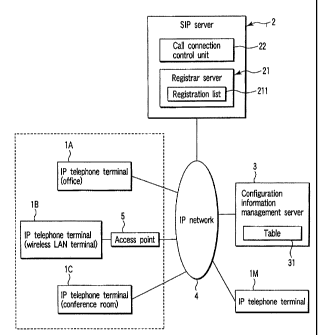
FIG. 1 is an exemplary block diagram showing an IP
telephone system regarding an embodiment of the present
15 invention;
FIG. 2 is an exemplary flowchart showing an
operation procedure of an IP telephone terminal in the
IP telephone system regarding the embodiment of the
present invention;
20 FIG. 3 is an exemplary view showing a table with
an upper limit number of IP telephone terminals capable
of being simultaneously log in by each user registered
therein;
FIGS. 4A to 9D are exemplary views showing a
25 registration list indicating correspondence between
each IP telephone terminal and user ID;
FIG. 5 is an exemplary block diagram of an IP
CA 02530924 2005-12-20
- 5 -
telephone system regarding a second embodiment of the
present invention;
FIG. 6 is an exemplary block diagram of an IP
telephone system regarding a third embodiment of the
5 present invention; and
FIG. 7 is an exemplary block diagram of an IP
telephone system regarding a fourth embodiment of the
present invention.
DETAILED DESCRIPTION OF THE INVENTION
10 Hereinafter, embodiments of the present invention
will be explained by referring to the drawings.
FIG. 1 is an entire view of an IP telephone system
regarding an embodiment of the present invention.
In FIG. 1, the IP telephone system comprises a
15 plurality of IP telephone terminals 1 (lA-1M), an SIP
server 2, a configuration information management server
3 and an IP network 9 which connects each of the
constituent elements given above.
The IP telephone system regarding the embodiment
20 sets the upper limit number of the IP telephone
terminals ? allowed to simultaneously log in the IP
telephone system for each user. This upper limit
number is associated with each user to be stored in the
configuration information management server 3. The IP
25 telephone terminal 1 downloads the upper limit number
for a user fram the management server 3 and downloads
the number of IP telephone terminals which have already
CA 02530924 2005-12-20
-- 6 -
logged in, from a registrar server 21 of the SIP server
2 to collate and compare between the two numbers in
accordance with a log-in operation by the user. If the
number of the IP telephone terminals which have already
5 logged in reaches the upper limit number, the user who
has performed the log-in operation is not allowed to
log in the IP telephone system. Therefore, the IP
telephone system can reduce IP address management, user
ID management and call connection processing and
10 prevent the load on the SIP server 2 from being
increased.
Any user of the IP telephone system obtains each
proper identification number (hereinafter, referred to
as user ID) "U1"-"Un". When a user make a telephone
15 call by means of an IP telephone terminal 1 (for
example, IP telephone terminal lA), a user ID is input
to an IP telephone terminal lA.
It is assumed that three sets of IP telephone
terminals 1A-1C are used by the users with user ID of
20 "Ul". The IP telephone terminal 1A is installed in an
office. An IP telephone terminal 1B is a wireless LAN
terminal to be connected to the IP network 4 through an
access point 5. An IP telephone terminal 1C is
installed in a conference zoom. The user with a user
25 ID of "Un" uses an IP telephone terminal 1M.
The SIP server 2 has a registrar server 21. The
registrar server 21 has a registration list 211
CA 02530924 2005-12-20
therein. The registration list 21I registers
information in which identification information~of the
IP telephone terminals lA-1M and the user IDs "U1"-"Un"
of the user who use the IP telephone terminals lA-1M
S are made in pairs, respectively. The SIP server 2 also
includes a call connection management unit 22 to
control call connection of the IP telephone terminals
which have logged in to the IP telephone system.
The configuration information management server 3
10 stores a table 31 to manage the upper limit number of
the IP telephone terminals 1A-1M to which each user can
simultaneously log in. The SIP procedure of the
embodiment automatically performs log-in processing to
the IP telephone system when the registrar server 21
15 receives registration information of terminal users
from the IP telephone terminals 1 to store it in the
registration list 211. The Sip server 2 does not
perform log-in control to the IP telephone terminals 1.
FIG. 2 is the exemplary flowchart showing the
20 operation procedures in the IP telephone system in
FIG. 1. Operations and processing procedures in the IP
telephone system will be described in parts of (1) log-
in processing up to the upper limit number, (2)
compulsory log-in processing, and (3) re-log-in
25 processing (continuation of log-in, and log--out).
(1) Log-in processing up to the upper limit number
It is assumed that the IP telephone terminal lA
CA 02530924 2005-12-20
_ g _
and the IP telephone terminal 1M are tuned on under a
condition in which the user IDs and the IP addresses of
the IP telephone terminals 1 are not registered in the
registrar server 21 (step s101). Both IP telephone
S terminals lA and 1M acquire own IP addresses, IP
address of the SIP server 2 and IP address of the
configuration management information server 3 in
accordance with a dynamic host configuration protocol
(DHCP) procedure (step s102).
10 Next, the user ID "U1" is input to the IP
telephone terminal lA (step s103). This user ID is
input in accordance with a prescribed procedure through
key buttons or the like of the IP telephone terminals
1. If the IP telephone terminals are ones to which
15 personal computers or the like are used, the user IDs
may be input through the keyboards of the computers or
the like.
The IP telephone terminal lA accesses to the IP
network 4 and downloads configuration information,
20 showing the upper limit number "2" of the IP telephone
terminals 1 having the user IDs "Ul" and possible to be
simultaneously registered, from the configuration
management information server 3 to read out it (step
slOA). The input of the user ID "Un" to the IP
25 telephone terminal 1M results in downloading of "3" to
the IP telephone terminal 1M in a procedure similar to
one given above.
CA 02530924 2005-12-20
_ g _
FIG. 3 is an exemplary view showing a table 31
stored in an internal memory of the configuration
management information server 3. In FIG. 3, the upper
limit numbers of the IP telephone terminals 1 possible
5 to simultaneously log in are initially preset for each
user "U1"-"Un" who have registered into the management
server 3, as the users of the IP telephone system. Two
sets for the User "U1" and three sets for the user "Un"
are stored as the respective upper lime numbers in the
10 table 31. This initial setting is executed by an
administrator through, for example, a management
terminal (not shown) connected to the management server
3 or the IP network 4. The initial setting gives the
upper limit number of the IP telephane terminals,
15 possible to log in for each user "U1"-"Un", to the IP
telephone system.
Next to this, each IP telephone terminal lA and 1M
downloads the registration list 211 with the input user
ID (for example "Ul" for telephone terminal lA) and its
20 user "U1" registered therein from the registrar server
21 to read out the already registered number "0" of
the user "U1" (step s105). In this case, the number of
the IP telephone terminals 1 is one by collating and
comparing the number of the IP telephone terminals 1 to
25 the upper limit number "2" of the user "Ul", which has
been read out by downloading the table 31 from the
management server 3, and the number "1" is not more
CA 02530924 2005-12-20
- 10 -
than the upper limit number possible to log in, so that
the IP telephone system determines that the telephone
terminal may log in thereto (No, in steps s107 and
s108). Then the IP telephone system transmits data of
5 a suite of the IP address and the user ID of its own IP
telephone terminal lA to the registrar server 21 to
register it (step s109).
Registrar server 21 receives this registration
information to write, store and register it in the
10 registration list 211 then the TP telephone terminal
lA is logged in the IP telephone system. The SIP
server 2 then constantly monitors the registration list
211 of the registrar server 21 to perform call
connection control between the registered IP telephone
1S terminals 1.
That is to say, each IP telephone terminal lA, if
furthermore a telephone number of a call arrival
destination is input by the user "Ul" after logging in
the IP telephone system, transmits the telephone number
20 to the SIP server 2 to request call connection (step
s110). The call connection control unit 22 of the SIP
server 2 receives the call request then performs the
call connection control between the IP telephone
terminal 1 having the telephone number of the call
25 arrival destination. These procedures up to the call
connection processing go the same for the IP telephone
terminal 1M.
CA 02530924 2005-12-20
- 11 -
FIG. 4 shows the registration list 211 showing
combinations of each IP telephone terminal 1 and user
IDs stored in the internal memory of the registrar
server 21. The (a) of FIG. A shows a state immediately
5 after the IP telephone terminals lA and 1M are
registered for the first time. The IP telephone
terminal 1A is registered for a user who has a terminal
ID "lA", a terminal IP address "192.168.100.1" and a
user ID "U1" and described as an address
10 Ul@192.168.100.1 that makes a pair with the user ID
"Ul". And an IP telephone terminal 1M is registered
for a user who has a terminal ID "1M", an IP address
"192.168.100.3" and a user ID 'Un' and described as
"Un@192.168.100.3". The TP address indicating the
15 association to bring the user and the IP telephone
terminal into a pair may be either a global address or
a local address.
Next to this, it is assumed that the user turns on
an IP telephone terminal 1B that is the wireless LAN
20 terminal. The IP telephone terminal 1B operates the
same operations as those of the aforementioned IP
telephone terminal lA, then downloads the registration
list 211 from the registrar server 21 and conducts the
operations up to step s106 in FIG. 2 in which the
25 number of the already registered sets of the IP
telephone terminals having the User ID "Ul" is collated
and compared to the upper limit number of sets possible
CA 02530924 2005-12-20
-- I2
to be registered. When reading out the registration
list 211, it is determined that one set has already
been registered for the user "U1" and log-in should be
allowed because the total number of sets becomes two
5 and settles not more than the upper limit number "2"
even after registration of its own terminal and
conducts processing after step s109 as similar to the
processing of previous time. The (b) of FIG. 4 is the
registration list 211 when the user "U1" is registered
10 in the IP telephone terminal 1B. The IP telephone
terminal 1B is registered in the user with a terminal
ID "1B", an IP address "192.168.200.5" and a user ID
"U1" and described as "U1@192.168.200.5"
(2) Compulsory log-in processing
15 Compulsory log-in is performed at the time when a
user wants to further log in the IP telephone system in
which other users have already lagged in through the TP
telephone terminals as many as the upper limit number.
The TP telephone terminal 1 of the user who has
20 forcibly logged in is treated to be logged out by timer
processing so as to be settled within the upper limit
number, as below-mentioned description (3) about re-
log-in.
Furthermore, operations of an IP telephone
25 terminal 1C in the case that the user "U1" further
moves to a conference room from an office and tries to
make a telephone call from the IP telephone terminal 1C
CA 02530924 2005-12-20
- 13 -
placed in the conference room then enters a waiting
state for the compulsory log--in will be described.
The user "U1" inputs the user ID "Ul" to the IP
telephone terminal 1C so as to make the IP telephone
5 terminal 1C log in before making a telephone call (step
s103). The IP telephone terminal 1C then downloads the
maximum upper limit number "2" of the IP telephone
terminals respectively having the user IDs "U1" from
the management server 3 and a current registration list
10 211 shown in the (b) of FIG. 9 from the registrar
server 21 (steps s109 and s105). Arid the IP telephone
terminal 1C collates and compares between the pre-
registered number of the IP telephone terminals 1 in
relation to the user ID "U1" and the upper limit number
15 (step s106). The IP telephone terminal 1C then reads
the registration 211 to determine that more
registration is not allowed and the user should wait
for an input for the compulsory log-in, because the
number of the IP telephone terminal 1C results in the
20 third one and exceeds the upper limit number (Yes, in
step s107) and the IP telephone terminal 1C (namely,
own telephone terminal) has not registered in the
registration list 211 (step s113).
After this, the IP telephone terminal 1C notifies
25 an alarm of impossibility of log-in to the user "Ul" by
some means. Here, means for displaying a lamp (not
shown) attached to the IP telephone terminal 1C (for
CA 02530924 2005-12-20
- 14 -
example, lighting off a display for communicability, or
lighting on alarm for incommunicability), for not
outputting a tone signal from a telephone receiver, or
for outputting an alarm for impossibility of log-in is
used.
The user "U1" who has come to know the alarm
determines that ordinal registration (log-in) is
. impossible. The user "U1" then tries to input a
compulsory log-in command through a prescribed key
button operation (Yes, in step s114). At this time,
the IP telephone terminal 1C transmits registration
information about a combination of the IP address
"192.168.100.2" and the user ID "U1" to the registrar
server 21 (step s109) to perform the compulsory log-in
to the IP telephone system and further transmits a
telephone number, which has been input by the user
"U1", to the STP server 3 to make a telephone call
(step s110).
The (c) of FIG. 4 is an exemplary view showing the
registration list 211 of the registrar server 21
immediately after the implementation of the compulsory
log-in. In the (c) of FIG. 4, the user "Ul" should be
registered two sets at a maximum fundamentally; however
the compulsory log-in has been performed, so that total
three sets of the IP telephone terminals 1 have been
registered in the registration list 211 exceptionally.
On the contrary, it is assumed that the user
CA 02530924 2005-12-20
- 15 -
suspends to make a telephone call from the IP telephone
terminal 1C because of the impossibility of log'-in of
the user "U1" (No, in step s114). In this case, the IP
telephone terminal 1C holds steady to wait for the
5 input of the command of the compulsory log-in and does
not conduct a log-in operation.
(3) Re-log-in processing (continuation of log-in,
and log-out)
In SIP procedures, the registrar server 21
10 automatically deletes each IP telephone terminal 1 of
which the time progress reaches a prescribed period,
respectively (for example, thirty minutes) from the
registration list 211. The IP telephone terminals 1
which have been logged in are logged out. Accordingly,
15 each IP telephone terminal 1 therefore executes
procedures to re-log in (re-register) to avoid-log-out
and allow them to be continuously used (step s111).
Two methods are provided for the re-log-in
processing. A first method automatically conducts the
20 re-log-in processing before a prescribed period (for
example, thirty minutes) is elapsed (for example,
fifteen minutes that is a half of the prescribed
period) after the log-in. A second method respectively
inputs the re-log-in commands to the IP telephone
25 terminals 1.
(First Method)
In the first method, depending on the same manner
CA 02530924 2005-12-20
- 16 -
in the conventional SIP procedures, each IP telephone
terminal 1 automatically conducts the re-log-in
processing at a time point when a half time of the
prescribed period (for example, fifteen minutes)
5 elapses by referring to a timer (not shown) after
logging in. Now, it is assumed that a time period (for
example, thirty minutes after the last log-in), in
which the user "Ui" requires to re-log-in (re-register)
by means of the IP telephone terminal lA in the office
10 while the user "U1" is in meeting in the conference
room, has elapsed.
Being in the conference room, the user "Ul" cannot
perform the re-log-in operation for the iP telephone
terminal lA; however the IP telephone terminal lA
15 automatically re-logs in before the fifteen minuets
elapses (step s115).
That is, the IP telephone terminal lA, of which
the timing for the re-log-in has reached, inputs for
the re-log--in (Yes, in step s115) to download the
20 registration list 211 from the registrar server 21
(step s105) and compares to the upper limit number of
the user "U1" (step s106).
If the number of the IP telephone terminals 1 by
which the user "U1" are now logging in is less than the
25 upper limit number allowed to be registered (No, in
steps s107 and s108 in FiG. 2), the user "U1" transmits
the IP address and the user ID of its own terminal to
CA 02530924 2005-12-20
- 17 -
the registrar server 21 to overwrite- register them and
logs in again.
It is assumed that the number of the IP telephone
terminals by which the user "Ul" are now logging in
5 reaches the upper limit number allowed to be registered
(Yes, in step s107 in FIG. 2). In this state, since
the registered terminal number is equal to the upper
limit number resulting from automatic re-Iog-in to
check the already-registered terminal number and its
10 own terminal has already registered in the registration
list 211 (Yes, in step s112), the user "U1" transmits
the IP address and the user ID "Ul" of its own terminal
to the registrar server 21 to register them for the re-
log-in (step s109) and terminates the re-log-in
15 processing. In the aforementioned two examples, the
user "Ul" can make a telephone call from the IP
telephone terminal lA without having to conduct the
log-in processing when returning to the office.
In contrast, if the number of the IP telephone
20 terminals 1 by which the user "Ul" is now logging in
exceeds the upper limit number allowed to be registered
(Yes, in steps s107 and s108), the IP telephone
terminal lA is brought into a compulsory log-in waiting
state. Since the user "Ul" is in the conference room,
25 an operation for the compulsory log-in is not conducted
from the IP telephone terminal 1A in the office (No, in
step sIl4). The IP telephone terminal 1A then expires
CA 02530924 2005-12-20
- 18 -
and automatically logs out.
Similarly, the registrar server 21 watched the
elapsed time period after receiving the registration
information of the IP telephone terminal lA by the
5 internal timer. After the elapse of the prescribed
period (thirty minutes) after the last log-in success
of the IP telephone terminal lA, the TP telephone
terminal 1A is deleted from the registration list 211.
As mentioned above, if the number of the IP
10 telephone terminals 1 registered in the registration
list 211 is not more than the upper limit number of the
user "U1", the IP telephone terminals 1 which have
logged in once are not deleted from the registration
list 211 and retain the log-in states successively as
15 long as commands for log-out are not input respectively
by the user "Ul".
The first method is convenient because the IP
telephone terminals 1 are not logged out and do not
need procedures to perform re-log-in processing as long
20 as the number of the IP telephone terminals 1 being in
log-in is not more than the upper limit number.
(Second Method)
In the second method, the user inputs the re-log-
in command to the IP telephone terminals 1 within the
25 prescribed time period (wherein, thirty minutes) in
which the registrar server 21 updates the registration
list 211.
CA 02530924 2005-12-20
- 19 -
Now, it is assumed that the user "Ul" makes a
radio communication through an IP telephone terz'ninal 1B
that is a wireless LAN terminal and makes a telephone
call at an appropriate time by using the IP telephone
5 terminal 1A. However, when the time, immediately
before (for example, one minute) the elapse of thirty
minutes after the first log-in without making any
telephone call by using the IP telephone terminal lA,
comes, the IP telephone terminal lA displays an alarm
10 to prompt the re-log-in (re-registration) by a lamp in
accordance with the internal timer. The user "Ul"
recognizes the alarm by the lamp to perform the re-log-
in and, for example, the user presses the key button in
accordance with prescribed procedures so as to input
15 the re-log-in command (Yes, in step s115). (As a
matter of course, the IP telephone terminal 1 may
automatically log out without output the alarm to
prompt the re-registration as described above after the
lapse of the re-registration time.)
20 The IP telephone terminal 1A with the re-log-in
command input thereto downloads the registration 21I
from the registrar server 21 in accordance with the
procedures in step s105. When the IP telephone
terminals 1A reads the registration list 211, the user
25 "Ul" determines that the IP telephone terminal 1B has
also been registered and the IP telephone terminal 1A
intends to be re-registered in a state of the upper
CA 02530924 2005-12-20
- 20 -
limit number "2" of the user "U1" (Yes, in step s 107).
Then, the IP telephone terminal 1A further
collates whether or not the IP address of its own
terminal is present in the registration list 211 to
5 read the description of U1@192.168.100.1 and determines
that it is possible to register the IP telephone
terminal lA if its own IP address is present in the
registration list 211 (Yes, in step s112j. The IP
telephone terminal lA executes a procedure of the re-
10 log-in processing to transmit the registration
information of the ID of the user "U1" and the IP
address of the TP telephone terminal lA (step s109).
As another case, it is assumed that a time period
(for example, thirty minutes), which is required for
15 the IP telephone terminal lA in the office to re-log in
(re-register), elapses while the user "U1" is in a
meeting in the conference room. Since the user "Ul" is
in the conference room, even when the registered number
in relation to the compulsory log-in operations or the
20 user "Ul" does not reach the upper limit, the command
operation for the re-log-in is not conducted (No, in
step s115), so that the IP telephone terminal 1A
expires and automatically logs out.
Likewise, the registrar server 21 watches the
25 elapsed time period after receiving the registration
information of the IP telephone terminals 1 by the
internal timer. Then, after the elapse of the
CA 02530924 2005-12-20
- 21 -
prescribed time period (thirty minutes) after the last
log-in success of the IP telephone terminal lA,! the IP
telephone terminal lA is deleted from the registration
list 211.
5 The second method is effective in the case that an
allowable amount limit of terminals in the IP telephone
system is strict, because the corresponding IP
telephone terminal is automatically logged out and
deleted from the registration list 211, even if the
10 number of the IP telephone terminals during connection
is not reaches the upper limit number as long as the
re-log-in command is not input.
The (d) of FIG. 9 shows the registration list 211
of the registrar server 21 in a state that the IP
15 telephone terminals lA and 1B log out and only the IP
telephone terminal 1C logs in after the compulsory log-
in is performed.
The IP telephone terminal 1 which has become in a
state waiting for the compulsory log-in may read out
2Q the registration list 211 of the registrar server 21 at
a fixed time interval to detect the fact that the IP
telephone terminals 1 become possible to log in.
For example, in the (c) of FIG. 4, while the IP
telephone terminal 1M by which the user ~~U1" intends to
25 make a telephone call at a moving destination executing
the procedure of waiting for an input of the compulsory
log-in (step s113), the IP telephone terminal 1M
CA 02530924 2005-12-20
- 22 -
automatically downloads the registration list 211 from
the registrar server 21 periodically, for examp~.e, with
every several minute interval (step s105). The IP
telephone terminal 1M then determines that the number
5 of the IP telephone terminals to log in becomes not
more than the upper limit number (here, assumed as two)
even if the IP telephone terminal 1M itself is logged
in by detecting the log-ouL of the IP telephone
terminals lA and 1B when the IP telephone terminal 1M
10 is brought into a state of the (d) of FIG. 9. The IP
telephone system can prompt the user "U1" to input the
user ID and the telephone number to make a telephone
call by indicating the fact that the IP telephone
terminal 1M is in the state of possibility of log-in
15 thereto by means of a lamp or the like. The IP
telephone terminal 1C may automatically transmit the
registration information and log in in stead of the
log-in operation by the user "U1" when the IP telephone
terminal 1C determines to be able to log in during
20 waiting for the compulsory log-in.
Although the IP telephone system of the embodiment
in the present invention is configured to comprise a
configuration information management server 3
independently in FIG. 1, each of the servers may be
25 configured to be independent with one another, or
configured to be in a combination thereof or to be
built in other server, other than the configuration
CA 02530924 2005-12-20
- 23 -
shown in FIG. 1.
FIG. 5 is, for example, an exemplary block diagram
showing a second embodiment of the invention in which
the SIP server 3, registrar server 21 and configuration
5 information management server 3 are independently
configured to be connected to the IP network 4. FIG. 6
is an exemplary block diagram showing a third
embodiment of.the invention in which the registrar
server 21 and configuration information management
10 server 3 are built in the SIP server 2 and inner buses
connect each server. Furthermore, FIG. 7 is an
exemplary block diagram showing a fourth embodiment of
the invention that is an apparatus in which a server 20
incorporates the IP server 2, registrar server 21 and
15 configuration information management server 3 are
incorporated, or that is a system configuration. In
this case, each server is connected through either the
IP network 4 or the inner buses. Even in the second to
fourth embodiments of the invention, the operation
20 procedures or the like in the IP telephone system,
namely, among the IP telephone terminals and each
server are similar to those of the first embodiment.
As given description, the IP telephone system of
the present invention sets the upper limit number of
25 the iP telephone terminals and makes the SIP telephone
terminal itself control whether its log-in is allowed
or not. Thereby, the situation, in which the user can
CA 02530924 2005-12-20
- 29 -
make a telephone call from any IP telephone terminal
without any limitation, is prevented. Consequently,
the IP telephone system can suppress a load increase in
IP address management, user ID management and call
5 connection processing.
Additional advantages and modifications will
readily occur to those skilled in the art. Therefore,
the invention in its broader aspects is not limited to
the specific details and representative embodiments
10 shown and described herein. Accordingly, various
modifications may be made without departing from the
spirit or scope of the general inventive concept as
defined by the appended claims and their equivalents.