Note: Descriptions are shown in the official language in which they were submitted.
CA 02531139 2008-11-10
Motor Vehicle Energy Regulator
The present invention concerns a motor vehicle comprising at least
one electric motor, an energy storage device for providing drive energy for
the electric motor, a plug connector connected to the energy storage device
for connection to a current source and a control means for controlling the
flow of current from the current source to the energy storage device.
Such vehicles have already been known for some time and are
eminently suitable for journeys over short and medium distances. In order
to make such a vehicle usable the available energy storage device has to
be charged up. When the vehicle has covered a certain distance the storage
device has to be charged up again. In that case, a careful driver will re-
charge the energy storage device after each journey in order always to
have at his disposal the greatest possible range.
As state of the art reference is made generally at this point to the
following publications: DE 692 20 228; DE 197 22 644 and DE 43 37 978,
As journeys with the vehicles - like also with all other vehicles -
cannot always be exactly planned in advance, it can happen with such a
procedure that the energy storage device of the vehicle is to be charged up
precisely when the cost of the energy is at its highest, and when in addition
the supply network is most heavily loaded, for example during what is
referred to as a midday peak.
That is disadvantageous both because of the high price of buying the
energy while it is also disadvantageous because of the loading on the
supply network which in any case is already highly loaded.
Therefore the object of the invention is to provide a motor vehicle
which can contribute to moderating the loading at consumption peaks in
the network.
That object is attained by a motor vehicle of the kind set forth in the
opening part of this specification, in that the control means permits a flow
of current from the energy storage device to the current source. In that
CA 02531139 2008-06-04
2
way a flow of current can take place from the energy storage device of the
motor vehicle back into the network and can thus contribute to covering
the peak demand.
In a preferred embodiment of the invention the flow of current from
the energy storage device to the current source, that is to say for example
into the current network, is controlled in such a way that a predeterminable
residual amount of electrical energy is retained in the storage device, by
the control means interrupting the flow of current to the network when said
predetermined residual charge amount is reached. For that purpose, there
is provided a device for detecting the amount of charge in the energy
storage device.
In a preferred development of the invention the control means
communicates with the network through a communication device so that
the draw of energy can be controlled in the optimum fashion from the
network, in dependence on the location of the motor vehicle and the
available amount of charge.
Particularly preferably the control means is designed in such a way
that it includes a clock or is connected to a clock. In that way the control
means can operate in such a fashion that charging and discharging
operations take place in predeterminable periods of time. It is possible in
that way to provide that the energy storage device is preferably charged up
at night when on the one hand the loading on the supply network is low
and on the other hand the costs of charging it up are low, while discharging
preferably takes place at times when relieving the load on the supply
network makes sense and the costs of the energy are higher than the costs
during the charging procedure. In that way it is also possible to achieve an
economic advantage, from the point of view of the operator of the vehicle,
besides relieving the load on the supply network.
CA 02531139 2008-06-04
2a
A Brief Description of the Drawinas
Fig. la shows a block diagram of a first embodiment of the invention;
Fig. lb shows a block diagram of an alternative embodiment of the
invention;
Fig. 2 shows a conventional day chart of the power demand in case of
an electrical power supply utility; and
Fig. 3 Shows a charge condition time table with the charge condition
for a vehicle according to the invention.
An embodiment of the invention is described in greater detail
hereinafter with reference to the Figures.
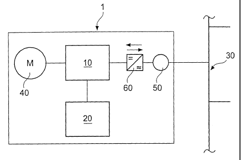
Figure 1 shows a simplified block circuit diagram of the arrangement
according to the invention. Reference 1 denotes a frame which includes
those components which are associated with the motor
25
CA 02531139 2006-01-03
3
vehicle. Accordingly the motor vehicle includes a control means 10. The
control means 10 is connected to an energy storage device 20, a drive
motor 40 and a releasable connector 50 which for example is in the form of
a piug connector. There is also a connection between the connector 50 and
a current source 30 which here is indicated in the form of an electrical
current supply network.
In order to provide sufficient energy for operation of the motor
vehicle 1, the control means 10 monitors the charge condition of the
storage device which can be for example a battery but also a capacitor
storage device or the like. When the storage means 10 recognises that
charging of the storage device 20 is required, the control means allows a
flow of current from the network 30 to the storage device 20 by way of the
connector 50 and the storage device is charged up. It will be appreciated
that, in that case, the control means 10 can also take account of the
corresponding charging characteristics of the storage device so that
overcharging of the storage device is reliably prevented.
The control means can also permit charging in a predeterminable
first period of time. That makes it possible for the storage device 20 to be
preferably charged up at night when on the one hand the price of the
electric current is low and thus the costs involved in charging the storage
device also remain comparatively low while on the other hand the loading
on the supply network 30 is not very high. In addition the control means
can be so designed that it permits a flow of current from the storage device
20 by way of the plug connector 50 and an inverter 60 into the network 30.
In that respect the amount of charge which can be delivered can be limited
by a predeterminable residual amount of charge at the storage device 20.
In that way for example after a journey to the place of work, with
the storage device 20 fully charged, the energy which is still present in the
storage device can be fed into the network 30 again if the demand is
particularly high, for example for the midday peak. However the control
means interrupts the flow of current from the storage device 20 into the
network 30 when a predeterminable residual amount is reached, so that at
CA 02531139 2006-01-03
4
any event an adequate amount of energy in the storage device for the
return journey in the evening is guaranteed.
It will be appreciated that the current which is fed into the network
at the peak time is to be suitably reimbursed so that, besides the aspect of
relieving the load on the network, there is also an economic advantage to
be achieved.
It was proposed in accordance with the invention that a vehicle with
an electrical energy storage device is also to be used as an energy source
for a power supply network from which the vehicle possibly draws its
energy.
As is known the power demand during the day is markedly higher
than the power demand at night. Thus for example the power demand in a
public power supply network rises from a low point at between 1 o'clock
and 4 o'clock at night in the morning (morning peak), reaches its highest
level (midday peak) around midday and then decreases in the evening
again until it reaches its low level in the middle of the night. As therefore
the energy demand at night is markedly lower than the usual available
energy supply and the consumers also take night-time power, it is
markedly lower in price than the price for daytime power.
An electrical power supply network then has to be designed in such a
way that it has to cover without any problem not only the demand at night,
but also the demand at the highest daytime peaks. In regard to the
electrical supply utilities, that means that a large number of electrical
energy generators must be provided, which reliably guarantee that such a
demand is met, even at very high midday peaks (on a cold winter's day).
Now, at this point, the invention proposes that an electric vehicle
which usually draws its electrical energy from an electrical supply network
and which therefore also has suitable connections with a connection to an
electrical power supply network can no longer be charged up with the
electrical energy from the power supply network, but if necessary, at a
given moment in time, can also feed energy that is not required, into the
supply network.
CA 02531139 2006-01-03
If it is first assumed that the vehicles have to be used by the
population working on weekdays, only in the periods between 7 am and
8.30 am and about 4.30 pm and 6.30 pm, such a motor vehicle is in a
parking place, without being used, for most of the day. Charging up the
5 energy storage device of the electric vehicle at night at the home of the
owner of the vehicle is not a problem and has also already been done.
What is new however is the proposal according to the invention that, after
the motor vehicle has reached the place of work, it is also connected to an
electrical current network in order then to provide the energy which is
necessary as required, for the peak power times.
If in that case the motor vehicle has batteries which
discharge/charge up very quickly, it is therefore possible, just with a
number of 500 - 1000 units of that nature, to provide a very high level of
feed-in power for the network.
The particular advantage for the electrical power supply utility is that
it can have recourse to an electrical energy storage device which it has not
paid for itself and for the maintenance of which it also does not have to
bear responsibility. From the point of view of the user of the vehicle, the
advantage of the invention is that, for example at the midday time when
therefore he does not in any case require his motor vehicle because he is at
his place of work, he virtually rents the storage device, which is still well
filled, of his vehicle, to the electrical power supply utility, and can sell
the
energy contained therein. The consumer can therefore feed the electrical
energy from his vehicle into the power supply network at midday and will
receive a comparatively good price, while at night he has to arrange for
charging up his vehicle at a good price (night-time current).
It will be appreciated that, in accordance with the invention, it is also
provided that the electrical storage device of the vehicle does not fall below
a given minimum level and, if necessary, the electrical storage device of
the vehicle can also be charged up again after the midday peak, more
specifically when the demand in the network has decreased again in the
afternoon.
CA 02531139 2006-01-03
6
It can however also be provided that the user individually adjusts his
vehicle in such a way that, in the evening, he has sufficient energy to
complete his journey home (minimum content of energy with a sufficient
level of certainty of arriving home) so that total charging of the storage
device is only effected again during the following night, with the
corresponding night-time current.
Therefore, by means of suitable programming (possibly also by way
of remote input (the user employing his cellular phone)), the user of the
vehicle can also predetermine the periods or the times within which only
discharging of his storage device can take place.
The invention is suitable in particular in conurbations where there are
large parking lots and large multi-storey car parks. The invention seems to
be quite particularly suitable for use in multi-storey car parks at airports,
in
particular those airports which carry holiday traffic, for at such car parks
there are often many thousands of private cars which are completely
unused for an average of 7 - 14 days. During that period, a suitable power
management system at the corresponding connection of the vehicles, if
they are in the form of electric vehicles according to the invention, could be
made available to the electrical power supply network which discharges the
respective storage devices of the vehicles at peak times and charges the
storage devices of the vehicles with electrical energy again at the periods of
lower demand.
The invention is described in greater detail hereinafter by means of
an embodiment illustrated in the drawing.
Herein Figure 1 - as described - shows an overview of the connection
of a vehicle according to the invention to an electrical power supply
network. Figure 2 shows a conventional day chart of the power demand in
the case of an electrical power supply utility. Figure 3 shows a charge
condition time table with the charge condition of a vehicle according to the
invention.
The electrical storage device of the vehicle 1 is equipped with a
suitable electronic control means (power management system) which
CA 02531139 2006-01-03
7
makes it possible to trigger and control not only electrical charging but aiso
discharging of the storage device.
In addition the power management system can also be programmed
in such a way that discharging is possible only for a quite specific time
which is predetermined by the user. For example, it can be provided that
discharging and thus a feed of power into the electrical energy supply
network is possible only during the time from 10 am to 3 pm, otherwise,
when the vehicle is connected to the supply network, the battery is being
correspondingly charged.
The power management system can also be programmed in such a
way that, when discharging is effected in the period from 7 am to 4 pm,
charging does not take place straightaway, but charging occurs only in the
night period between 12 midnight and 4 am, that is to say when
particularly appropriate night-time current is to be taken from an electrical
supply network.
In addition the power management system of the vehicle can be
programmed in such a way that basically a minimum amount of charge
remains in the storage device, that is to say cannot be fed into the supply
network, in order in any case to ensure that the user can properly travel
the distance that he wants, in his vehicle, that is to say for example the
journey home from his place of work.
It will be appreciated that still further programming modes are
possible, so that the power management system can also be set by the
user himself, in just any conceivable manner, according to his respective
wishes, while if necessary there is the possibility of a feed into the power
supply network.
As can be seen from Figure 2 the current/energy demand of an
electrical supply utility (ESU) is not distributed linearly over the entire
day,
but rises from a lowest point early in the morning (about 1 am to 3 am),
reaches a first morning peak, then later reaches the so-called midday peak,
that is to say its highest point, and then decreases irregularly towards the
night again. The electrical power supply network which has the
responsibility of always making sufficient electrical energy available to the
CA 02531139 2006-01-03
8
consumers connected to the electrical supply network, even at peak times,
not only has to ensure that appropriate energy is fed into the supply
network, but also that there is always so much energy in readiness that, at
all times, that is to say even at extraordinary peak times, the responsibility
of providing an electrical supply with electrical energy at a constant voltage
level and a constant frequency is always met. It is apparent that a large
number of control interventions both on the producer side and also in terms
of the distribution of electrical energy is already required nowadays for that
purpose.
Figure 3 shows a configuration by way of example of the charge
condition of the electrical storage device of a vehicie according to the
invention. In the electrical storage device which was charged with night-
time current during the night, and which therefore exhibits a one hundred
percent filling (I), that charge condition falls, in the morning journey (II)
to
the place of work. When the place of work is reached (III) and the vehicle
is connected by way of the electric lines to the electrical supply network,
the charge condition is possibly returned to one hundred percent again. At
the midday time (IV), that is to say when the midday peak occurs (see
Figure 2), a large part of the stored electrical energy in the storage device
is fed into the connected electrical supply network so that the charge
condition correspondingly falls within a very short time to a prescribed
minimum (V). That minimum has been set by the user or the vehicle
manufacturer (it can also be set in another fashion) and should be sufficient
for the vehicle to be able to still make the journey home, without charging
it up beforehand.
In the illustrated example however the charge condition can also be
increased again in the afternoon (VI) by taking energy from the supply
network and during the journey home (VII) the charge condition further
falls again. When the electric vehicle is subsequently connected to the
electrical power supply network the charge condition can be restored to the
prescribed value (100%) again in the evening/at night (VIII).
It should be pointed out once again that the configuration as set
forth in Figure 3 is given purely by way of example.
CA 02531139 2006-01-03
9
If the electric vehicle has a suitable input surface, the user of the
vehicle can execute a large number of setting adjustments.
Thus for example, by means of a suitable input, the user can
predetermine the periods of time, within which only discharging of the
electrical storage device can take place at all, when connected to an
electrical supply network.
As corresponding documentation of the charging and discharging
operations shows, the user, even after several days, can still see when and
what amounts of energy were fed into the electrical supply network.
Besides the electrical storage device, for example a lithium battery or
another storage technology, the vehicle according to the invention has a
suitable power management program for controlling the charge condition of
the electrical storage device and for evaluation of the inputs of the user and
also for documentation purposes.
In addition the vehicle can have a suitable data interface (besides
receiver/transmitter for wireless (cellular phone) control) so that the
vehicle can send to or receive from a suitable interface of the electrical
power supply utility, all data which are necessary for charging and also for
discharging (feed into the network).
That facilitates documentation of the respective discharging and
charging conditions/times and billing thereof. In regard to billing, account
is
to be taken of the fact that current which is fed into the network at the
midday peak can be reimbursed at a better price that night-time current
which usually can be made availabie without any problem and at a better
price in relatively large amounts.
Discharging of the storage device with the feed of electrical energy
into the power supply network, that this then involves, can also be used for
possibly appropriately charging other vehicles with an electrical storage
device, the charge condition of which has become too low, to such an
extent that those vehicles can still continue to travel.
Therefore the invention also permits a plurality of vehicles to be
electricaliy connected together, with their electrical storage devices.
CA 02531139 2006-01-03
The present invention also provides that the electric current (electric
voltage) of the electrical storage device of the vehicle, for being fed into
the
current source (network), is converted by an inverter 60 so that the feed
into the current source is possible. That inverter can be provided in each
5 vehicle but on the other hand it is also possible for the electric current
of
the energy storage device to be firstly taken from the vehicle by direct
current transmission and for the inverter then to be provided outside the
vehicle (as viewed from the vehicle, downstream of the network and the
connection of the vehicle) so that the electrical power taken from the
10 vehicle can be produced by an inverter for the feed into the network (for
example 50 Hz, network voltage etc).
It is also particularly advantageous that a central inverter station is
provided - for the delivery of direct current for the storage device in the
vehicle but also for the feed of alternating current into the network -,
which for example is provided at garage installations (for example at
airports) as here large amounts of electrical energy can occur at such
garage installations if a correspondingly large number of vehicles according
to the present invention are connected. In that way the costs of the
inverters are overall kept at a relatively low level and at the same time it
is
possible to provide for a methodical feed of alternating current into the
electrical network as it is relatively simple to control individual or
relatively
large inverter stations than many small inverters in vehicles, which
ultimately could also result in disturbances, for example harmonics, in the
network.
As an inverter also has a degree of efficiency of less than 1, even if it
is only slightly below the ideal vaiue of 1, the losses from an inverter in a
vehicle (Figure la) are certainly higher than in the case of a stationary,
central inverter (Figure ib).
In the case of a domestic connection also the inverter can be
associated therewith so that an individual vehicie can certainly also feed
back energy, at its parking space at home.
As it is certainly the case that working people frequently have to
cover reasonable distances and do not use the vehicles throughout the
CA 02531139 2006-01-03
11
entire working day, there is a statistically demonstrable basic supply of
electrical energy which is available for most of the time (working time). If
that energy is regularly available those storage devices can also make a
contribution to the regulating energy of wind power installations, which is
being discussed at present and which is required in the network. That is
particularly attractive if the vehicle storage devices are charged from
regenerative sources. More specifically then those regenerative energy
sources themselves generate and provide at least a part of the regulating
energy required.