Note: Descriptions are shown in the official language in which they were submitted.
CA 02531154 2005-12-21
METHOD OF MANUFACTURING A NEEDLE ASSEMBLY FOR USE
WITH A BIOPSY DEVICE
FIELD OF THE INVENTION
[0001] The present invention is related generally to biopsy devices and, more
particularly, to an improved process of manufacturing a needle assembly for
use with a
biopsy device for acquiring a tissue sample.
BACKGROUND OF THE INVENTION
[0002] The diagnosis and treatment of patients with cancerous tumors, pre-
malignant
conditions, and other disorders has long been an area of intense
investigation. Non-
invasive methods for examining tissue include palpation, thermography, PET,
SPECT,
Nuclear imaging, X-ray, MRI, CT, and ultrasound imaging. When the physician
suspects
that tissue may contain cancerous cells, a biopsy may be done either in an
open procedure
or in a percutaneous procedure. For an open procedure, a scalpel is used by
the surgeon to
create a large incision in the tissue in order to provide direct viewing and
access to the
tissue mass of interest. Removal of the entire mass (excisional biopsy) or a
part of the
mass (incisional biopsy) is performed. For a percutaneous biopsy, a needle-
like
instrument is inserted through a very small incision to access the tissue mass
of interest
and to obtain a tissue sample for later examination and analysis.
[0003] The advantages of the percutaneous method as compared to the open
method are
significant: less recovery time for the patient, less pain, less surgical
time, lower cost, less
risk of injury to adjacent bodily tissues such as nerves, and less
disfigurement of the
patient's anatomy.
[0004] Generally there are two ways to percutaneously obtain a portion of
tissue from
within the body: aspiration and core sampling. Aspiration of the tissue
through a fine
needle requires the tissue to be fragmented into pieces small enough to be
withdrawn in a
CA 02531154 2005-12-21
fluid medium. This method is less intrusive than other known sampling
techniques, but
one may only examine cells in the liquid (cytology) and not the cells and the
structure
(pathology). In core sampling, a core or fragment of tissue is obtained for
histologic
examination and/or genetic tests, which may be done via a frozen or paraffin
section. The
type of biopsy used depends mainly on various factors present in the patient,
and no
single procedure is ideal for all cases. However, core biopsies seem to be
more widely
used by physicians.
[0005] The following patent documents are incorporated herein by reference for
the
purpose of illustrating biopsy devices and methods: US Patent 5,526,822 issued
June 18,
1996; US 5,895,401 issued April 20, 1999; US Patent 6,086,544 issued July 11,
2000; US
Patent 6,620,111 issued Sept. 16, 2003; US Patent 6,626,849 issued September
30, 2003;
US Patent 6,638,235 issued Oct 28, 2003; US Patent Application 2003/0109803
published June 12, 2003; US Patent Application 2003/0199753 published Oct 23,
2003;
US Patent Application 2003/0199754 published Oct. 23, 2003; US Patent
Application
2003/0199785 published Oct. 23, 2003; and US Serial Number 08/825,899 filed on
April
2, 1997.
[0006] It is known in the art to use a double lumen biopsy needle
incorporating vacuum
suction to obtain a tissue sample. With devices of this type, the needle is
inserted into a
small incision in a patient and is advanced through tissue until the needle is
adjacent the
tissue of interest. At that point, a vacuum source may be activated, providing
suction
inside one of the two lumens. The suction is communicated to the second lumen
via a
passage between the two lumens. The second lumen may contain an aperture
through
which suspicious tissue may be drawn when the vacuum source is activated. Once
tissue
is drawn into the aperture, the surgeon may advance a cutter through the
second lumen in
order to excise a sample from the tissue of interest.
-2-
CA 02531154 2005-12-21
[0007] While biopsy needles of the type described above are useful in
obtaining tissue
samples, the processes known in the art for manufacturing these needles are
often
expensive and labor-intensive due to the number of components and steps
involved. For
instance, certain biopsy needles provide a double lumen structure formed of
two separate
rigid structures, thus requiring a reliable method of attaching the two
structures, such as a
weld or adhesive, along the entire length of the lumens. Similarly, many
biopsy needles
include a sharpened feature on the leading end of the needle that cuts through
tissue as
the needle is advanced into the body. These sharpened tips often have small
components
and/or features that require significant time and expense to make and attach
to the needle.
Further, biopsy needles often include a mounting component that allows the
needle to be
attached to a handle or other platform. Often, these mounting components are
manufactured separately from the body of the needle, and must be joined
together after
formation, such as by gluing, a process that is heavily reliant on the skill
and
concentration of a human worker. Even if a more reliable method of attaching
the
mounting component to the needle is used, such as induction heating or heat
staking, such
methods still involve the added expense necessitated by the extra assembly
equipment as
well as the steps of manufacturing the mounting component and attaching it to
the needle.
[0008] Accordingly, while double lumen biopsy needles are known in the art,
there exists
a significant need for a process of manufacturing a biopsy needle that reduces
the number
of components that must be separately manufactured, as well as the time and
labor that
must be expended in manufacturing and assembling the components of the biopsy
needle,
while still maintaining the necessary strength and rigidity for safe and
satisfactory
performance during surgery.
-3-
CA 02531154 2005-12-21
SUMMARY OF THE INVENTION
[0009] The process of the current invention overcomes the above-noted and
other
deficiencies of the prior art by providing a process for manufacturing a
biopsy needle
device that reduces the number of components that must be separately
manufactured and
assembled, thereby reducing the cost of manufacturing the biopsy needle device
while
maintaining the necessary biomechanical properties.
[0010] In one aspect consistent with the present invention, a process of
manufacturing a
biopsy needle may comprise the steps of forming an aperture for receiving
tissue to be
sampled in an exterior surface of an elongated tube that has a proximal and
distal portion,
wherein the elongated tube may be configured to receive a cutter; forming a
hole in the
exterior surface of the elongated tube; and applying a coating of material
over the
elongated tube to form a lumen for receiving vacuum on the exterior surface of
the
elongated tube, wherein the hole in the exterior surface of the elongated tube
may be
adapted to provide communication between an interior of the elongated tube and
an
interior of the lumen. This process advantageously allows the vacuum lumen to
be
formed over the elongated tube without requiring separate manufacturing and
assembly
steps, thus reducing assembly costs.
[0011] In another version, the process of manufacturing the biopsy needle
device may
comprise the steps of forming an aperture for receiving tissue to be sampled
in an exterior
surface of an elongated tube, wherein the elongated tube may be adapted to
receive a
cutter and may further comprise a proximal portion and a distal portion;
forming a hole in
the exterior surface of the elongated tube; and placing the elongated tube in
a mold and
injecting the mold with a material, wherein the mold may be configured such
that the
material forms a lumen for receiving vacuum on the exterior surface of the
elongated
tube, and wherein further the hole in the exterior surface of the elongated
tube may be
adapted to provide communication between an interior of the elongated tube and
the
-4-
CA 02531154 2005-12-21
interior of the lumen. This version advantageously provides for the formation
of a
vacuum lumen on an elongated tube by overmolding a coating of material onto
the
elongated tube, avoiding the need to separately manufacture the vacuum lumen
and then
attach it to the elongated tube. Further, this process may provide for a
stronger attachment
between the vacuum lumen and the elongated tube than some previously known
methods
of attachment of the two components.
[0012] In another aspect, the process of manufacturing a biopsy needle device
may
comprise the steps of placing a cutter tube, which may comprise a port adapted
to receive
a tissue sample and may further comprise a cutter lumen adapted to receive a
cutter, in a
mold; injecting a material in a liquid state into the mold; cooling the
material in order to
convert it to a solid state; wherein the mold may be configured to cause the
material to
form a lumen for receiving vacuum on an exterior surface of the cutter tube,
and wherein
further the vacuum lumen is in communication with the cutter lumen.
[0013] The present invention also extends to a biopsy instrument manufactured
according
to a process that may comprise the steps of forming an aperture for receiving
tissue to be
sampled in an exterior surface of an elongated tube for receiving a cutter,
wherein the
elongated tube may have a proximal portion and a distal portion; forming a
hole in the
exterior surface of the elongated tube; and applying a coating of material
over the
elongated tube to form a lumen for receiving vacuum on the exterior surface of
the
elongated tube, and wherein the hole in the exterior surface of the elongated
tube may be
adapted to provide communication between an interior of the elongated tube and
an
interior of the lumen.
(0014] These and other objects and advantages of the process of the present
invention
shall be made apparent from the accompanying drawings and the description
thereof.
-5-
CA 02531154 2005-12-21
BRIEF DESCRIPTION OF THE DRAWINGS
[OOIS] The novel features and steps of the invention are set forth with
particularity in the
appended claims. The invention itself, however, both as to organization and
methods of
operation, together with further objects and advantages thereof, may best be
understood
by reference to the following description, taken in conjunction with the
accompanying
drawings in which:
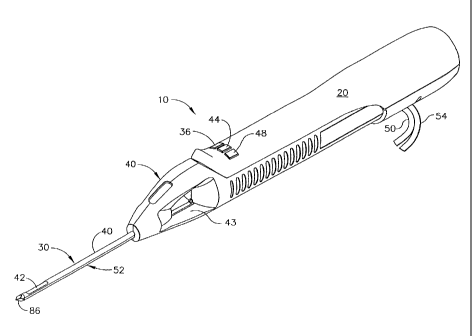
[0016] FIGURE 1 is an isometric view of a hand-held vacuum-assisted biopsy
device
including a needle assembly manufactured according to one version of the
process.
[0017] FIGURE 2 is a side view of a needle assembly manufactured according to
one
version of the process.
[0018] FIGURE 3 is a top view of a needle assembly manufactured according to
one
version of the process.
[0019] FIGURE 4 is a side view of a distal tissue-piercing tip manufactured
according to
one version of the process.
[0020] FIGURE 5 is an isometric view of a distal tissue-piercing tip
manufactured
according to one version of the process.
[0021] FIGURE 6 is a section view of a cutter lumen and cutter stop
manufactured
according to one version of the process.
[0022] FIGURE 7 is a section view of a cutter stop manufactured according to
one
version of the process.
[0023] FIGURE 8 is a partial view of a cutter lumen and axial slide according
to one
version of the process.
-6-
CA 02531154 2005-12-21
[0024] FIGURE 9 is an isometric view of a needle assembly with slides in place
for use
in injection molding according to one version of the process.
[0025] FIGURE 10 is a partial frontal cross-sectional view of a needle
assembly
manufactured according to one version of the process.
[0026] FIGURE 11 is a partial sagittal cross-sectional view of a needle
assembly
manufactured according to one version of the process.
DETAILED DESCRIPTION OF THE INVENTION
[0027] FIG. 1 shows a hand-held vacuum-assisted biopsy device 10 comprising a
handle
20 detachably connected to a needle assembly 30 having a proximal portion 32
and a
distal portion 34 manufactured according to a version of the process of the
current
invention. Together, they constitute a lightweight, ergonomically-shaped, hand-
manipulated biopsy device 10. In one aspect, needle assembly 30 may be part of
a
disposable probe that may mount on handle 20. In one aspect, hand-held biopsy
device 10
may be used in conjunction with an ultrasound to guide needle assembly 30.
Since handle
20 may be manipulated by the operator's hand, the operator may steer needle
assembly
30 with great freedom towards the tissue mass of interest. The surgeon has
tactile
feedback while doing so and may therefore ascertain to a significant degree
the density
and hardness of the tissue being encountered. In addition, handle 20 may be
held
approximately parallel to the chest wall of a patient for obtaining tissue
portions closer to
the chest wall than may be obtained when needle assembly 30 is attached to
another type
of device. Alternatively, needle assembly 30 may be attached to an
electromechanical
arm, a platform, a table or other suitable support. Such alternative mountings
may be
used in conjunction with applications in which the needle assembly is guided
by
stereotactic (x-ray) or MRI modalities.
[0028] As controls for obtaining a tissue sample, handle 20 may include a
forward button
36 which may be used to move a cutter 38 distally through a cutter lumen 40 to
sever a
CA 02531154 2005-12-21
sample of suspicious tissue collected in a tissue-receiving port 42. Handle 20
may further
include a reverse button 44 which may be used to move cutter 38 proximally
through
cutter lumen 40, thereby moving the tissue sample in port 42 to a tissue
collection surface
46. A vacuum button 48 on handle 20 may be used to open or close a first
vacuum line 50
for communicating suction to a vacuum lumen 52 so as to cause tissue to become
disposed within port 42 and a second vacuum line 54 for communicating axial
suction to
cutter 38 to aid in withdrawal of a severed tissue sample.
[0029] Referring now to FIGS. 2 and 3, a needle assembly 30 made by one
version of the
process of the current invention for use with a biopsy device 10 is
illustrated. Cutter
lumen 40 may comprise a proximal portion 56 and a distal portion 58. Cutter
lumen 40
forms a smooth, uninterrupted passage for receiving cutter 38 such that it may
be
advanced through the proximal portion 56 of cutter lumen 40 to the distal
portion 58.
Tissue-receiving port 42 may be formed in an exterior surface 60 of cutter
lumen 40. Port
42 may be located on the distal portion 58 of cutter lumen 40. Cutter lumen 40
may also
comprise an open proximal end 62 and an open distal end 64.
[0030] Vacuum lumen 52 may comprise a proximal portion 66 and a distal portion
68. In
one version, cutter lumen 40 may be oriented above vacuum lumen 52. A vacuum
source
(not pictured) may be attached to vacuum lumen 52, possibly at proximal
portion 66
thereof, via first vacuum line 50.
[0031) The needle assembly 30 may also include one or more passages, also
called
interlumen vacuum holes 70, between cutter lumen 40 and vacuum lumen 52. When
the
vacuum source is activated, thereby providing suction in vacuum lumen 52,
interlumen
vacuum holes 70 allow that suction to be communicated into cutter lumen 40. As
best
illustrated in FIGS. 3 and 11, the interlumen vacuum holes 70 may be located
between
cutter lumen 40 and vacuum lumen 52 opposite the tissue-receiving port 42. As
illustrated in FIG. 6, a cutter stop 72 may also be located in cutter lumen 40
distally of
_g_
CA 02531154 2005-12-21
tissue-receiving port 42. A face 74 of cutter stop 72 may provide a cutting
surface for
severing a tissue sample. Face 74 of cutter stop 72 may be designed to match
the leading
profile of cutter 38 (FIGS. 6 and 7). Depending on the means used to advance
cutter 38,
cutter stop 72 may also provide tactile feedback to a surgeon once cutter 38
comes into
contact with cutter stop 72 after a sample has been severed. However, if, as
known in the
art, a computer software program is used to control advancement of cutter 38,
the surgeon
will not be provided with tactile feedback by contact between cutter 38 and
cutter stop
72.
[0032] As illustrated in FIG. 2, a hub 76 having a proximal portion 78 and a
distal
portion 80 may be located on proximal portion 32 of needle assembly 30. Hub 76
assists
in mounting needle assembly 30 to handle 20 or other any other suitable
support. Hub 76
may detachably mount on handle 20 in order to allow disposable needle assembly
30 to
be removed from the multiple-use handle 20 after surgery. Hub 76 may also
include a
flange 82 (not pictured) on its proximal portion 301. Flange 82 may snap into
a rib or
similar retaining element of handle 20 or another suitable support. Hub 76 may
also
include a vacuum manifold 84 that provides a connection between the vacuum
source and
vacuum lumen 52. Hub 76 may also allow second vacuum line 54 to connect with
cutter
38 so that axial suction may be communicated to cutter 38.
[0033] In one aspect consistent with the process of the current invention, a
distal tissue-
piercing tip 86 having a proximal portion 88 and a distal portion 90 may be
disposed on
distal portion 34 of needle assembly 30. As best pictured in FIGS. 4 and 5,
distal portion
90 of distal tissue-piercing tip 86 may include a cutting edge 92 of
sufficient sharpness to
cut through human tissue and thereby aid in moving needle assembly 30 adjacent
the
tissue of interest. The junction of piercing tip 86 and cutter lumen 40 may
include a
tapered profile 94 therebetween that further assists needle assembly 30 in
moving
smoothly through a patient's tissue.
-9-
CA 02531154 2005-12-21
[0034] Piercing tip 86 may comprise a substantially flat blade formed of any
suitable
material. Piercing tip 86 may also include tabs 96, 98 on proximal portion 88
thereof to
aid in the attachment of piercing tip 86 to cutter lumen 40. Tab 96 may be
located above
tab 98. In one version, tab 98 extends further toward proximal end 62 of
cutter lumen 40
than does tab 96 for reasons addressed below. Piercing tip 86 may also include
an
opening 100, to aid in formation of tapered profile 94, which is also
discussed in more
detail below.
[0035] In operation, needle assembly 30 may be inserted into a small incision
in the
body. When utilized, tissue-piercing tip 86 helps needle assembly 30 penetrate
through
tissue until distal portion 34 of needle assembly 30 is located adjacent the
tissue of
interest. Piercing tip 86, along with tapered profile 94, may help to minimize
tissue drag
experienced during insertion and extraction of needle assembly 30. Once needle
assembly
30 is properly positioned relative to the tissue of interest, vacuum suction
may be applied
to vacuum lumen 52 via first vacuum line 50.
[0036] Suction may be communicated from vacuum lumen 52 to cutter lumen 40 via
the
interlumen vacuum holes 70. The suction inside cutter lumen 40 actively pulls
suspicious
tissue into tissue-receiving port 42. Once the suspicious tissue has been
drawn into cutter
lumen 40 through port 42, the surgeon may advance cutter 38 in the distal
direction until
a sample is severed from the suspicious tissue. Cutter stop 72 may be located
in cutter
lumen 40 distally of tissue-receiving port 42 to provide a cutting surface to
aid cutter 38
in severing a sample of suspicious tissue. Once the sample has been severed,
cutter 38
may contact cutter stop 72. As mentioned above, depending on the means used to
advance cutter 38 through cutter lumen 40, contact between cutter 38 and
cutter stop 72
may provide tactile feedback to the surgeon, indicating that a sample has been
obtained
and that cutter 38 may be withdrawn toward proximal end 62 of cutter lumen 40.
Once
cutter 38 contacts cutter stop 72, needle assembly 30 may be repositioned in
the patient's
body (e.g., rotated, longitudinally translated) in order to obtain another
sample.
-10-
CA 02531154 2005-12-21
[0037] As mentioned above, cutter 38 may be attached to second vacuum line 54,
thereby
providing cutter 38 with axial suction. After a sample has been obtained, and
before a
second sample is drawn into port 42, axial suction, if utilized, may assist
cutter 38 in
pulling the sample through cutter lumen 40 as cutter 38 is withdrawn. Once
cutter 38 has
been withdrawn from cutter lumen 40, the sample may be cleared from cutter 38
onto a
tissue collection site 46 located on handle 20 or platform. At that point,
another sample
may be obtained by applying vacuum to draw a sample into port 42 and advancing
cutter
38 to sever the sample. This procedure may be repeated until the desired
number of
samples has been acquired.
[0038] In one aspect consistent with the process of the current invention,
cutter lumen 40
may comprise a preformed tube open at each end and cut to the desired length
of needle
assembly 30. The preformed tube may be advantageously straight and round for
receiving
cutter 38. The material of the preformed tube may be rigid to allow insertion
of needle
assembly 30 through tissue with minimal deflection. In one version, cutter
lumen 40 may
be made of metal. More particularly, cutter lumen 40 may be made of stainless
steel.
Cutter lumen 40 may also be made from other suitable materials, including but
not
limited to titanium, titanium alloy, aluminum, or aluminum alloy.
Alternatively, cutter
lumen 40 may be made from nonmetallic materials having structural
characteristics
sufficient to allow a coating of material to be applied over cutter lumen 40
and having the
strength and rigidity characteristics sufficient to withstand the force
experienced by cutter
lumen 40 when it is pressed through human tissue.
[0039] Tissue-receiving port 42 and interlumen vacuum holes 70 may be cut into
the
preformed tube comprising cutter lumen 40. As shown in FIG. 3, the distal and
proximal
edges of port 42 may be cut on an angle relative to the longitudinal edges of
port 42. The
angling of these edges can produce a scissoring effect as needle assembly 30
is pushed
through tissue, aiding in positioning the device 10. In addition, a pair of
notches (not
-11-
CA 02531154 2005-12-21
pictured) may be cut into distal end 64 of the preformed tube comprising
cutter lumen 40
to provide points of attachment for piercing tip 86.
[0040] Piercing tip 86 may be formed of a material providing sufficient
strength and
rigidity to allow it to move through tissue with minimal deflection. In one
version, tip 86,
including the above-described features included thereon, may be stamped from
metal
sheet stock. More particularly, the metal may be 440A stainless steel.
However, other
suitable materials may be used, including but not limited to titanium,
titanium alloy,
aluminum, or aluminum alloy. Non-metallic materials, such as MRI compatible
resins,
including but not limited to Ultem and Vectra, may be used to form tip 86.
Likewise, tip
86 may also be formed from ceramics or glass. By stamping piercing tip 86 out
of metal
sheet stock, cutting edge 92 may be sharpened prior to attachment of tip 86 to
cutter
lumen 40. Cutting edge 92 may be sharpened after formation of tip 86 by
grinding
perpendicular to cutting edge 92, which is sometimes thought to be
advantageous in
producing a sharp cutting surface. Alternatively, cutting edge 92 may be
sharpened by
any other suitable method known in the art.
[0041] Piercing tip 86 may be attached to cutter lumen 40. In one version,
piercing tip 86
may be welded to cutter lumen 40. More particularly, piercing tip 86 may be
laser welded
to cutter lumen 40. In one version, piercing tip 86 may be welded to cutter
lumen 40 at
two preformed locations. Tabs 96, 98 of piercing tip 86 may each be welded
inside a
notch of cutter lumen 40. Alternatively, piercing tip 86 may be attached to
cutter lumen
40 through any suitable method known in the art that provides satisfactory
strength of
attachment between tip 86 and cutter lumen 40, including but not limited to
adhesive,
press-fit, or screws.
[0042] Other features of needle assembly 30 may be formed by applying a
coating of
material over cutter lumen 40. The coating of material may be applied to
cutter lumen 40
as a liquid, and then hardened to the necessary rigidity for use in the human
body after
-12-
CA 02531154 2005-12-21
formation of the desired features thereon. In one version, the coating of
material may be
applied to cutter lumen 40 by injection molding. In this version, the mold
(not pictured) is
designed such that the injected material may flow into predetermined cavities
and form
the desired features over cutter lumen 40, including but not limited to vacuum
lumen 52
and hub 76. The gates (not pictured) through which the material is injected
into the mold
may be located along the mold part line, shown as PL in FIG. 9. Further, the
gates may be
located in the mold underneath cutter lumen 40.
[0043] In this version, when the material is injected into the mold, it may
form an outer
sheath 106 over cutter lumen 40, as well as tapered profile 94 between
piercing tip 86 and
cutter lumen 40. To assist in formation of tapered profile 94, piercing tip 86
may include
opening 100 (FIG. 4) through which the injected material may flow. Flow of
injected
material through opening 100 from each side of tip 86 may strengthen
attachment of the
injected material to piercing tip 86.
[0044] The mold may also be shaped so that the applied material forms hub 76,
flange
82, and vacuum manifold 84 over proximal portion 56 of cutter lumen 40. The
mold may
also be designed so that hub 76 extends past proximal end 62 of cutter lumen
40 in order
to facilitate the mounting of needle assembly 30 to handle 20 or another
suitable support.
Alternatively, hub 76, including flange 82 and vacuum manifold 84 may be
formed
separately from the remainder of needle assembly 30 and be attached by gluing,
press-
fitting or any other suitable method known in the art.
[0045] Referring to FIG. 9, prior to application of the coating of material, a
slide 108
may be placed along exterior surface 60 of cutter lumen 40, substantially
parallel to the
longitudinal axis thereof. More particularly, slide 108 may be placed on the
underside of
exterior surface 60. The material then coats cutter lumen 40 and slide 108,
forming
vacuum lumen 52 substantially parallel to the longitudinal axis of cutter
lumen 40. Slide
108 also serves to prevent the applied material from blocking interlumen
vacuum holes
-13-
CA 02531154 2005-12-21
70. The mold may also be designed so that slide 108 may be placed in alternate
locations
in order to orient vacuum lumen 52 above or to either side of cutter lumen 40,
so long as
at least one interlumen vacuum hole 70 is present between vacuum lumen 52 and
cutter
lumen 40 to allow suction to be communicated therebetween.
[0046] While use of slide 108 is one process for forming vacuum lumen 52 in
the coating
of material applied over cutter lumen 40, it is recognized that other methods
of forming
vacuum lumen 52 in the coating of material are also possible. For example,
vacuum
lumen 52 could be drilled out of the coating of material after the material
reaches
sufficient hardness.
[0047] As shown in FIG. 10, in one version consistent with the invention, the
coating of
material provides the combined cutter lumen 40 and vacuum lumen 52 with an egg-
shaped frontal cross-section 110. During surgery, cross-section 110 promotes
efficient
motion of the needle assembly 30 through tissue. However, it is recognized
that the
application of a coating of material to cutter lumen 40 may provide needle
assembly 30
with cross-sections of various shapes that are consistent with the process of
the current
invention. Further, as illustrated in FIGS. 9 and 10, slide 108 may comprise a
scoop-
shaped cross-section 111 that provides vacuum lumen 52 with a generally scoop-
shaped
frontal cross-section 112. While this is helpful in providing the combined
cutter lumen 40
and vacuum lumen 52 with the egg-shaped frontal cross-section 110 described
above,
vacuum lumen 52 and slide 108 could comprise various frontal cross-sections
that are
consistent with the process of the current invention. For instance, slide 108
could have a
circular frontal cross-section, thus providing vacuum lumen 52 with a circular
frontal
cross-section.
[0048] As shown in FIGS. 4 and 5, tab 98 on piercing tip 86 may be elongated
and slope
downward in the proximal direction. In addition to serving as a point of
attachment for
-14-
CA 02531154 2005-12-21
welding piercing tip 86 to cutter lumen 40, tab 98 may also align and help
hold slide 108
in place during molding.
[0049) Prior to application of the material to cutter lumen, a slide 112 (FIG.
9) may be
inserted into tissue-receiving port 42. Slide 112 prevents any of the applied
material from
entering port 42.
[0050] Referring now to FIGS. 8 and 9, an axial slide 114 having a proximal
end 116 and
a distal end 118 may be inserted into open proximal end 62 of cutter lumen 40
prior to
application of the coating of material. Axial slide 114 prevents the applied
material from
entering proximal end 62 of cutter lumen 40. Further, axial slide 114 may be
of a
predetermined length such that distal end 118 extends into cutter lumen 40
distally of
tissue-receiving port 42 but does not reach open distal end 62 of cutter lumen
40. Distal
end 118 of slide 1 14 may further comprise an indentation 120. Piercing tip 86
may be
attached to distal end 64 of cutter lumen 40 in a manner that does not prevent
material
from flowing into open distal end 64 during application of the material over
cutter lumen
40. Accordingly, during the application process, material flows into open
distal end 64 of
cutter lumen 40 and into indentation 120 in axial slide 114, thereby forming
cutter stop
72 in cutter lumen 40 distally of tissue-receiving port 42.
[0051] Additionally, in one version of the present invention, one or more
slides may be
placed against exterior surface 60 of cutter lumen 40 in order to hold cutter
lumen 40 in
position while the material is applied over cutter lumen 40 and prevent
deformation due
to the pressure of the applied material against exterior surface 60. As a
result, outer
sheath 106 may include windows 122 (FIG. 3) through which cutter lumen 40 is
exposed.
[0052] The injected material may be selected from materials including, but not
limited to,
plastics, thermoplastics, thermoresins, and polymers. For instance, the molded
features
may be formed of a liquid crystal polymer or a glass reinforced polymer. One
suitable
material is a glass reinforced liquid crystal polymer such as VECTRA A130
available
-15-
CA 02531154 2005-12-21
from Ticona Corp. In one version, the injected material may have a melt flow
index of at
least about 10 grams/minute, more particularly at least about 15 grams/minute.
Without
being limited by theory, such a mold flow index is thought to be beneficial
for molding
relatively long, thin-walled cross-sections.
[0053] While various versions of the present invention have been shown and
described
herein, it will be obvious to those skilled in the art that such alternatives
are provided by
way of example only. Numerous variations, changes, and substitutions will now
occur to
those skilled in the art without departing from the present invention.
Additionally, each
component or element may be described in terms of a means for performing the
component's function. Accordingly, it is intended that the invention be
limited only by
the spirit and scope of the appended claims.
[0054] What is claimed is:
- 16-