Language selection

Search

Patent 2531289 Summary

Third-party information liability

Some of the information on this Web page has been provided by external sources. The Government of Canada is not responsible for the accuracy, reliability or currency of the information supplied by external sources. Users wishing to rely upon this information should consult directly with the source of the information. Content provided by external sources is not subject to official languages, privacy and accessibility requirements.

Claims and Abstract availability

Any discrepancies in the text and image of the Claims and Abstract are due to differing posting times. Text of the Claims and Abstract are posted:

  • At the time the application is open to public inspection;
  • At the time of issue of the patent (grant).
(12) Patent: (11) CA 2531289
(54) English Title: MODULE AND FRAME FOR CABLE ENTRIES
(54) French Title: MODULE ET CADRES POUR ENTREES DE CABLES
Status: Deemed expired
Bibliographic Data
(51) International Patent Classification (IPC):
  • H02G 3/22 (2006.01)
  • F16L 5/08 (2006.01)
(72) Inventors :
  • KREUTZ, TOMAS (Sweden)
(73) Owners :
  • ROXTEC AB (Not Available)
(71) Applicants :
  • ROXTEC AB (Sweden)
(74) Agent: MARKS & CLERK
(74) Associate agent:
(45) Issued: 2010-05-11
(86) PCT Filing Date: 2004-06-14
(87) Open to Public Inspection: 2004-12-23
Examination requested: 2005-12-16
Availability of licence: N/A
(25) Language of filing: English

Patent Cooperation Treaty (PCT): Yes
(86) PCT Filing Number: PCT/SE2004/000925
(87) International Publication Number: WO2004/112211
(85) National Entry: 2005-12-16

(30) Application Priority Data:
Application No. Country/Territory Date
0301750-6 Sweden 2003-06-17

Abstracts

English Abstract


The present invention concerns a module (3) and a frame (1) for cable entries,
pipe penetrations etc. The module (3) has end parts (7) and middle parts (8)
adaptable to receive flat cables (6) or the like having an elongated cross
section. The end parts (7) may be identical to parts forming a module (2) for
receiving cables, pipes etc. having a circular cross section. The frame (1) is
to receive one or more of said module (3).


French Abstract

L'invention concerne un module (3) et un cadre (1) pour des entrées de câbles, des passages tubulaires, etc. Ce module (3) comporte des parties terminales (7) et des parties médianes (8) adaptables pour recevoir des câbles plats (6) ou des éléments analogues à section transversale allongée. Les parties terminales (7) peuvent être identiques à des parties formant un module (2) destiné à recevoir des câbles, des tubes, etc. et doté d'une section transversale circulaire. Le cadre (1) peut contenir un ou plusieurs modules (3) de ce type.

Claims

Note: Claims are shown in the official language in which they were submitted.


6
The embodiments of the invention in which an exclusive
property or privilege is claimed are defined as follows:
1. A module to be received in a frame for cable entries
and/or pipe penetrations, the module comprising:
two end parts; and
two middle parts placed between the end parts to receive
flat cables and/or pipes having an elongated cross section,
wherein each middle part is formed of a base plate and a
number of sheets that may be peeled off to adapt the middle
part to the flat cable or the flat pipe to be received.

2. The module of claim 1, wherein each end part has a
number of sheets, giving a rounded form to receive an end
of the flat cable and/or the flat pipe, and which sheets
may be peeled off to adapt the end part to the received
flat cable or the flat pipe.

3. The module of claim 1 or 2, wherein the base plate is
to be directed away from the flat cable or the flat pipe at
mounting in a frame.

4. The module of any one of claims 1 to 3, wherein it is
made of an elastic material.

5. The module of any one of claims 1 to 4, wherein a
blind plate is arranged encircled by the end and middle
parts.

6. A frame for cable entries or pipe penetrations,
wherein the frame receives one or more modules as defined
in any one of claims 1 to 5.


7
7. The frame of claim 6, comprising tensioning means.

8. The frame of claim 7, wherein the tensioning means is
a wedge.

Description

Note: Descriptions are shown in the official language in which they were submitted.


CA 02531289 2008-06-04
1

APPLICANT: ROXTEC INTERNATIONAL AB

TITLE: Module and.Frame for Cable Entries

Technical Field
The present invention concerns a module and frame for
cable entries, pipe penetrations etc.

Prior Art
Frames of different kinds are normally used for cable
entries, pipe penetrations etc. The frame may receive ca-
bles for electricity, communication, computers etc. or
pipes for different gases or liquids such as water, com-
pressed air, hydraulic fluid and cooking gas. It is used in
many different environments, such as for cabinets, techni-'
cal shelters, junction boxes and machines and also decks
and bulkheads of ships. The frames may also be mounted in
walls or roofs of different types of buildings.
Different modules adapted to the cables or pipes to
be received are normally included in the frames. However,
these modules are normally only adapted to cables, pipes or
the like having a circular cross section. There are no spe-
cial modules for flat cables or the like. When receiving
flat cables it has been common to make special arrangements
in each frame. The person mounting the cables, pipes or the
like has made the adaptation. Thereby the result has in
some degree been depending on the skill of the person
mounting the cables etc. Thus, there is a need of modules
that may be readily adapted to the flat cables or the like
to be received in the frame.

Summary of the Invention
The invention is developed concerning parts not hav-
ing a circular cross section, e.g. flat cables. One object
SUBSTITUTE SHEET (RULE 26)


CA 02531289 2009-05-27
2

of the present invention is that the frame should be possi-
ble to adapt to the cross section of the part to be re-
ceived.
This object is meet by a module to be received in a
frame for cable entries, pipe penetrations etc. The module
has parts adaptable to receive flat cables or the like,
having an elongated cross section.
A further object of the present invention is that
handling should be improved, concerning mounting., storing
as well as transport.
The modules used are preferably adaptable to cables
of different dimensions, by means of peelable sheets. The
sheets are held together by an adhesive effect. The adhe-
sive effect is strong enough to normally keep the sheets
together, but not stronger than making it possible to peel
off a separate sheet by hand.
Further objects and advantages of the present inven-
tion will be obvious for a person skilled in the art when
reading the detailed description of at present preferred
embodiments below.
In one aspect, the invention provides a module to be
received in a frame for cable entries and/or pipe
penetrations, the module comprising:
two end parts; and

two middle parts placed between the end parts to receive
flat cables and/or pipes having an elongated cross section,
wherein each middle part is formed of a base plate and a
number of sheets that may be peeled off to adapt the middle
part to the flat cable or the flat pipe to be received.

Brief Description of the Drawings
The invention will be described further below by way
of examples and with reference to the enclosed drawings.
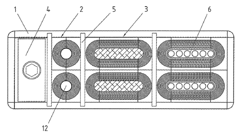
Fig. 1 shows an example of a frame having a module
according to the present invention, and
Fig. 2 is an exploded view of a module according to
the present invention.


CA 02531289 2008-06-04
2a

Detailed Description of Preferred Embodiments
In Fig. 1 a frame 1 for cable entries, pipe penetra-
tions etc. is shown. The frame 1 is to be received in a
wall, top, roof etc. As is known in the art a number of
modules 2, 3 are received in the frame 1. The modules 2,3
are made of an elastic material. In order to give a tight


CA 02531289 2005-12-16
WO 2004/112211 PCT/SE2004/000925
3

seal a wedge 4 or other tensioning means is arranged to put
pressure on the modules 2, 3, which will expand outwardly
due to the pressure. Between each set of modules 2, 3 a
partition 5 is arranged. The partitions 5 are arranged in
such a way that they may slide in the frame 1, due to the
pressure exerted by the wedge 4.
Of the shown modules 2, 3 one type of module 2 is for
cables, pipes or the like having a circular outer circum-
ference. This type of module is well known in the art and
will not be described extensively here. The other module 3
is to receive flat cables 6 or other parts having an elon-
gated and rounded outer circumference.
Even though the flat cables 6 are shown in Fig. 1
having a cross section with rounded, semicircular ends, a
person skilled in the art realises that the flat cables 6
may have other cross section forms. The present invention
has proved useful also for flat cables having a more or
less rectangular cross section. The corners of the cross
section of the cable often being somewhat rounded. The lat-
ter cases function due to the fact that the modules 3 are
elastic enough to take up the deviating cross sections.
Thus, end parts 7 having a rounded inner surface facing the
cable may be used even if the opposing surface of the cable
is virtually straight.
The module 3 for flat cables 6 has two end parts 7,
which may correspond to or be identical with the parts of
the module 2 for cables etc. having a circular cross sec-
tion. Between the end parts 7 two middle parts 8 are ar-
ranged. The end parts 7 have a number of sheets 9 that may
be peeled of to adapt the end parts 7 to the part to be re-
ceived. In the same way the middle parts 8 have sheets 10
that may be peeled off. Further, each middle part 8 has a
base plate 11. The base plate 11 is placed at the side of
the middle part 8 that is to be directed away from the ca-
ble 6 or the like at mounting. The end parts 7 have base
SUBSTITUTE SHEET (RULE 26)


CA 02531289 2005-12-16
WO 2004/112211 PCT/SE2004/000925
4

units 14 having a rectangular outer configuration and a
circular inner configuration. The circular inner configu-
ration is to receive a cable, pipe or the like. The peeling
sheets 9 are received on the inside of the circular part.
Depending on the dimensions of the flat cable 6 the
middle parts 8 of the module 3 may have varying length.
Usually it is enough to have a number of standard lengths
for the middle parts 8. It is also possible to have middle
parts 8 that are relatively long, in which case the middle
parts are cut to an appropriate length before mounting.
When the end parts 7 are used for a module 2 with
circular inner cross section, a blind rod 12 is usually
furnished to facilitate storing, transport and mounting. In
the modules 3 for flat cables 6 the blind rod 12 is re-
placed with a blind plate 13 placed between the middle
parts 8. The blind plate 13 has rounded ends to be received
in the end parts 7. In some embodiments there are no blind
plates 13.
As mentioned above identical units may be used for
the modules 2 for circular cables, pipes etc. and for the
end parts 7 of the modules 3 for flat cables or the like.
The use of identical units facilitates handling and stor-
ing.
In use the blind plate 13 is first taken away when a
flat cable 6 or the like is to be brought through the frame
1. Then the appropriate number of sheets 9, 10 are peeled
off from the end parts 7 and middle parts 8, respectively.
The appropriate number of sheets 9, 10 is that number that
is needed to give room for the flat cable 6 in the module
3. When the cables, pipes or the like have been mounted in
the frame 1 the wedge 4 or other tensioning means is ma-
nipulated to put pressure on the modules 2, 3 having ca-
bles, pipes, blinds 11, 12 etc. Due to the pressure exerted
by the wedge 4 or the like the elastic material of the mod-

SUBSTITUTE SHEET (RULE 26)


CA 02531289 2005-12-16
WO 2004/112211 PCT/SE2004/000925

ules will expand in the other directions, giving a tight
seal.

SUBSTITUTE SHEET (RULE 26)

Representative Drawing
A single figure which represents the drawing illustrating the invention.
Administrative Status

For a clearer understanding of the status of the application/patent presented on this page, the site Disclaimer , as well as the definitions for Patent , Administrative Status , Maintenance Fee  and Payment History  should be consulted.

Administrative Status

Title Date
Forecasted Issue Date 2010-05-11
(86) PCT Filing Date 2004-06-14
(87) PCT Publication Date 2004-12-23
(85) National Entry 2005-12-16
Examination Requested 2005-12-16
(45) Issued 2010-05-11
Deemed Expired 2012-06-14

Abandonment History

There is no abandonment history.

Payment History

Fee Type Anniversary Year Due Date Amount Paid Paid Date
Request for Examination $800.00 2005-12-16
Application Fee $400.00 2005-12-16
Maintenance Fee - Application - New Act 2 2006-06-14 $100.00 2005-12-16
Registration of a document - section 124 $100.00 2006-05-09
Maintenance Fee - Application - New Act 3 2007-06-14 $100.00 2007-05-16
Maintenance Fee - Application - New Act 4 2008-06-16 $100.00 2008-04-10
Maintenance Fee - Application - New Act 5 2009-06-15 $200.00 2009-04-16
Final Fee $300.00 2010-02-25
Maintenance Fee - Application - New Act 6 2010-06-14 $200.00 2010-04-13
Owners on Record

Note: Records showing the ownership history in alphabetical order.

Current Owners on Record
ROXTEC AB
Past Owners on Record
KREUTZ, TOMAS
ROXTEC INTERNATIONAL AB
Past Owners that do not appear in the "Owners on Record" listing will appear in other documentation within the application.
Documents

To view selected files, please enter reCAPTCHA code :


To view images, click a link in the Document Description column. To download the documents, select one or more checkboxes in the first column and then click the "Download Selected in PDF format (Zip Archive)" or the "Download Selected as Single PDF" button.

List of published and non-published patent-specific documents on the CPD .

If you have any difficulty accessing content, you can call the Client Service Centre at 1-866-997-1936 or send them an e-mail at CIPO Client Service Centre.


Document
Description 
Date
(yyyy-mm-dd) 
Number of pages   Size of Image (KB) 
Claims 2009-05-27 2 36
Description 2009-05-27 6 202
Representative Drawing 2006-02-20 1 37
Cover Page 2006-02-21 1 65
Claims 2005-12-16 1 44
Abstract 2005-12-16 1 83
Drawings 2005-12-16 1 48
Description 2005-12-16 5 188
Cover Page 2010-04-19 1 65
Claims 2008-06-04 2 38
Description 2008-06-04 6 202
Prosecution-Amendment 2007-12-05 3 101
PCT 2005-12-16 3 109
Assignment 2005-12-16 2 95
PCT 2006-01-27 4 186
Correspondence 2006-02-17 1 26
Assignment 2006-05-09 3 113
Correspondence 2006-05-09 1 40
Prosecution-Amendment 2008-06-04 8 208
Prosecution-Amendment 2008-11-27 1 30
Prosecution-Amendment 2009-05-27 5 128
Correspondence 2010-02-25 1 31