Note: Descriptions are shown in the official language in which they were submitted.
CA 02531334 2011-08-15
63293-4051
-1-
MAGNETIC PARTICLE SEPARATOR FOR AN ABRASIVE
JETTING SYSTEM
The present invention relates to a tool for
excavating an object.
In particular, the tool of the present invention.
comprises:
- a jetting system arranged to impinge the object to be
excavated with a jetted stream of a drilling fluid mixed
with abrasive particles, the jetting system being
provided with at,least a mixing chamber with a drilling
fluid inlet, a second inlet for abrasive particles, and
an outlet nozzle for releasing the drilling fluid mixed
with the abrasive particles;
- a recirculation system arranged to recirculate at
least some of the abrasive particles.
Such a tool can typically be provided on a lower end
of a drill string that is deployed in a subterranean bore
hole, whereby during operation the drilling fluid is.
pumped from surface through a longitudinal channel in the
drill string to the tool and essentially back to surface
in a return stream through an annular space between the
drill string and the bore hole wall.
In order to avoid continuous circulation of the
abrasive particles through the drill string and the
annular space, US 6,510,907 proposes to provide the tool
with a recirculation system for separating the abrasive
particles from the return stream and re-inserting these
particles into a mixing chamber through which the main
stream of drilling fluid is passed. Embodiments of the
recirculation system are based on a separator magnet for
magnetically separating the abrasive particles from the
return stream, which abrasive particles are made of a
magnetic material for that purpose.
CA 02531334 2011-08-15
63293-4051
-2-
Another such tool is described in International
publication WO 02/34653. The recirculation system of that
tool is based on a helical separator magnet that is
concentrically arranged within a support member. The
support member is formed by a cylindrical sleeve, of
which sleeve the outer surface forms a support surface on
which magnetic particles are retained by the magnetic
field generated by the helical separator magnet. The
separator magnet has a central longitudinal axis about
which the separator magnet is rotatable relative to the
sleeve.
When the separator magnet is driven into axial
rotation, the magnetic particles experience a moving
gradient of magnetic field strength perpendicular to the
helical groove, which the particles will follow. In this
way the particles are transported over the support
surface back to the jetting system for re-insertion into
the mixing chamber.
Both prior art tools rely on an efficient transfer of
the magnetic abrasive particles from the separator magnet
into the mixing chamber for entrainment with the stream
of drilling fluid..
In particular when a large number of abrasive
particles must be recirculated per time unit, the
transfer must be efficient or else the abrasive particle
inlet into the, mixing chamber can be blocked by an excess
of magnetic particles arriving at the inlet.
In order to improve the transfer, one aspect of the
invention provides a tool for excavating an object, the
tool comprising:
a jetting system arranged to impinge the object to
be excavated with a jetted stream of a drilling fluid
mixed with abrasive particles, the jetting system being
provided with at least a mixing chamber with a drilling
fluid inlet, a second inlet for abrasive particles, and
CA 02531334 2011-08-15
63293-4051
-3-
an outlet nozzle for releasing the drilling fluid mixed
with the abrasive particles;
a recirculation system arranged to recirculate at
least some of the abrasive particles, from a return
stream of the fluid mixed with the abrasive particles
downstream impingement of'the jet with the object back to
the jetting system, whereby the abrasive particles
comprise a magnetic material, which recirculation system
comprises a separator magnet for separating the abrasive
particles from said return stream and for transporting
the particles to the second inlet;
a piece of magnetic material that is provided in or
in the vicinity of the mixing chamber such as to draw a
part of the magnetic field generated by the separator
magnet into the mixing chamber.
Under influence of the separator magnet in the
recirculation system, the piece of magnetic material will
magnetize and an image pole-will be formed in the piece
of magnetic material having opposite polarity from the
pole on the separator magnet being exposed to the piece
of magnetic material. Magnetic field lines will cross
over from the pole on'the separator magnet to the induced
image pole in the piece of magnetic material, and thereby
part of the magnetic field generated by the separator
magnet is drawn into the mixing chamber. The magnetic
field gradient that the magnetic abrasive particles
experience is therefore lower locally in the vicinity of
the inlet for abrasive particles than it is elsewhere in
the vicinity of the separator magnet. For this reason,
the transfer efficiency of the abrasive particles from
the recirculation system into the mixing chamber is
improved.
Preferably, a part of the magnetic field in the
mixing chamber is directed essentially transverse to a
drilling fluid flow path between the drilling fluid inlet
CA 02531334 2011-08-15
63293-4051
-4-
and the outlet nozzle. Herewith it is achieved that the
magnetic particles are drawn into the mixing chamber in
the form of chains that run transverse to the flow
direction of the drilling fluid in the mixing chamber.
Herewith the interaction between the drilling fluid and
the abrasive particles is maximised so that the abrasive
particles can pick up kinetic energy with maximum
efficiency.
In an embodiment wherein the recirculation system
comprises a support surface to guide the abrasive
particles towards the second inlet, a shield can be
provided at a, distance from the support surface leaving a
gap between the shield and the support surface thereby
forming a path from the return stream to the second inlet
along the support surface.
Herewith fluid can be guided from the return stream
into the second inlet, thereby further supporting the
passage of the abrasive particles through the second
inlet into the mixing chamber.
Some embodiments of the invention will now be
illustrated by way of example, with reference to the
accompanying drawing wherein
Fig. 1. schematically shows a cross section of part
of a tool for excavating an object;
Fig. 2 shows a inap of the magnetic field lines in
cross section through line A--A;
Fig. 3 schematically shows a surface map of a
separator magnet surface arrangement in accordance with
the invention;
Fig. 4 (parts a to c) schematically shows various
alternative separator magnet surface arrangements in
accordance with the invention; and
Fig. 5 shows a schematic view of a tool for
excavating an object.
CA 02531334 2006-01-04
WO 2005/005768 PCT/EP2004/051428
-
In the figures, like parts carry identical reference
numerals. Where, in the following description, a
direction of rotation is specified, the direction of
transport is each time the viewing direction in relation
5 to which the rotary direction is defined.
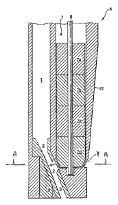
Part of a tool for excavating an object is
schematically shown in longitudinal section in Fig. 1.
The tool can be connected to the lower end of a drill
string (not shown) extending into a borehole formed in an
object such as an earth formation. The tool is arranged
to jet a stream of drilling fluid mixed with abrasive
particles against the object to be excavated and to
recirculate at least part of the abrasive particles. The
abrasive particles must be magnetisable for this tool.
The tool is provided with a longitudinal drilling
fluid passage 1, which is at one end thereof in fluid
communication with a drilling fluid channel provided in
the drill string and at the other end thereof in fluid
communication with a jetting system that comprises a
mixing chamber 2 that is connected to the drilling fluid
passage 1 via a drilling fluid inlet 3.
The mixing chamber 2 is also in fluid communication
with a second inlet 4 for abrasive particles (an abrasive
particle inlet) and with a mixing nozzle 5 having an
outlet (not shown) arranged to jet a stream of drilling
fluid and abrasive particles against the earth formation
during drilling with the drilling tool in the borehole.
The mixing chamber is provided with a piece of
magnetic material 14 on the side opposite from the
abrasive particle inlet 4.
The mixing nozzle 5 is arranged inclined relative to
the longitudinal direction of the drilling tool at an
inclination angle of 15-30 relative to vertical, but
other angles can be used. Preferably the inclination
angle is about 21 , which is optimal for abrasively
CA 02531334 2006-01-04
WO 2005/005768 PCT/EP2004/051428
6 -
eroding the bottom of the bore hole by axially rotating
the complete tool inside the bore hole. The mixing
chamber 2 and mixing nozzle 5 are aligned with an outlet
nozzle under the same angle, in order to achieve optimal
acceleration of the abrasive particles.
The drilling fluid passage 1 is arranged to bypass a
device 6 for transporting magnetic particles that is
included in the tool as part of a recirculation system
for the magnetic abrasive particles which can be used if
the abrasive particles contain a magnetic material. The
device 6 includes a support member in the form of a
slightly tapered sleeve 15 for providing a support
surface extending around an essentially cylindrically
shaped elongate separator magnet 7. The separator
magnet 7 generates a magnetic field for retaining the
magnetic particles on the support surface 15.
The drilling fluid passage 1 is fixedly arranged
relative to the support surface 15 and the mixing
chamber 2. The drilling fluid passage 1 has a lower end
arranged near the second inlet 4 for abrasive particles.
In the present embodiment the drilling fluid passage 1 is
formed inside a ridge in the axial direction which ridge
is in protruding contact with the support surface 15. The
drilling fluid passage 1 may alternatively be arranged
freestanding from the support surface in a manner similar
to that shown and described in International Publication
WO 02/34653 with reference to Fig. 4 therein, or in an
off-axial direction. The second inlet 4 for abrasive
particles is located at the lower and of the ridge.
The support surface 15 has a conical shape.
Alternatively, the support surface may be cylindrical.
The cylindrical separator magnet 7 is formed of four
smaller magnets 7a, 7b, 7c, and 7d stacked together. A
different number of the smaller magnets can also be used.
Each separator magnet 7a, 7b, 7c, and 7d has
CA 02531334 2006-01-04
WO 2005/005768 PCT/EP2004/051428
- 7 -
diametrically opposed N and S poles, and the magnets are
stacked in a manner that adjacent magnets have N-S
directions azimuthally rotated with respect to each other
about the central longitudinal axis 8 over an angle cp
such that two essentially helical diametrically opposing
bands are each formed by alternating N and S poles.
For the purpose of this specification, a magnetic
pole is an area on the magnet surface or on the support
surface where magnetic field lines cross the magnet
surface or the support surface thereby appearing as an
area of source or sink for magnetic field lines.
Due to the nature of a bipolar magnet, the magnetic
field strength in the regions between the N and S poles
in each of the smaller magnets 7a, 7b, 7c, and 7d is
lower than in the essentially helically aligned regions
around the N and S poles. In this way, the helical bands
of alternating N and S poles form a high-field band of
increased magnetic field strength relative to regions
forming low-field band displaced by about 90 in azimuth
with respect to that high-field band. In between the
high- and low-field bands, there is a gradient zone where
the magnetic field strength decreases from the increased
value in the high-field band to the value in the low-
field band.
The separator magnet 7 has a central longitudinal
axis 8 and is rotatable relative to the sleeve 15 and
about the central longitudinal axis 8. Drive means are
provided (not shown) to drive axis 8 and thereby rotate
the separator magnet 7 into either clockwise or counter
clockwise rotation as dictated by the sense of the
helical band. The drive means may advantageously be
provided in the form of an electric motor, which motor
may be controlled by a control system (not shown).
A short tapered section 11 is provided at the lower
end of magnet 7d. The sleeve 15 is provided with a
CA 02531334 2006-01-04
WO 2005/005768 PCT/EP2004/051428
- 8 -
corresponding conical taper in a manner that the second
inlet 4 for abrasive particles provides fluid
communication between the support surface 15 surrounding
the tapered section 11 and the mixing chamber 2. The
conical taper is best based on the same angle as the
above-discussed angle of the mixing chamber 2 and mixing
nozzle 5.
Fig. 2 shows a cross section along A-A as indicated
in Figs. 1 and 5, running through the magnet 7d
transverse to axis 8 and through the mixing chamber 2 and
the piece of magnetic material 14. The geometry is
suitable for counter clockwise rotation of the separator
magnet. The magnetic field strength is given for various
locations around the support surface 15 by means of a
grey-scale.
A portion of the magnetic field lines, for which
lines 20 are an example, run between poles on magnet 7d
of opposite polarity. The piece of magnetic material 14,
on the side opposite from the abrasive particle inlet 4
(compare Fig. 1), causes a portion of the magnetic field
lines to run from the lower end 11 of the separator
magnet to this piece of magnetic material 14. Magnetic
field lines 21 and 22 are an example of such bridge-
forming magnetic field lines.
Also visible in Fig. 2 is a shirt 43 and a gap 44
extending between the skirt 43 and the support
surface 15. This will be further explained below with
reference to Fig. 5.
In operation, the tool works as follows. The tool is
connected to the lower end of a drill string that is
inserted from the surface into a borehole. A stream of
drilling fluid is pumped by a suitable pump (not shown)
at surface, via the drilling fluid channel of the drill
string and the fluid passage 1 into the mixing chamber 2.
During initial pumping, the stream is provided with a low
CA 02531334 2006-01-04
WO 2005/005768 PCT/EP2004/051428
9 -
concentration of abrasive particles of magnetic material
such as steel shot or steel grit.
The stream flows from the mixing chamber 2 to the
mixing nozzle 5 and is jetted against the borehole
bottom. Simultaneously the drill string is rotated so
that the borehole bottom is evenly eroded. A return
stream, containing the fluid, the abrasive particles and
excavation debris, flows from the borehole bottom through
the borehole in a direction back to the surface. Thereby,
the return stream passes along the sleeve 15.
Simultaneously with pumping of the stream of drilling
fluid, the separator magnet 7 is rotated about its
axis 8, in a direction dictated by the sense of the
helical bands, which can be either clockwise or counter
clockwise. The separator magnet 7 induces a magnetic
field extending to and beyond the outer surface of the
sleeve 15. As the stream passes along the sleeve 15, the
abrasive particles in the stream are separated out from
the stream by the magnetic forces from the separator
magnet 7 which attract the particles onto the outer
surface of the sleeve 15.
The stream of drilling fluid, which is now
substantially free from abrasive magnetic particles,
flows further through the bore hole to the pump at
surface and is re-circulated through the drill string
after removal of the drill cuttings.
The magnetic forces exerted to the abrasive particles
are lower in the low-field band than in the high-field
band. The magnetic particles retained on the support
surface 15 are attracted towards the band having the
highest magnetic field. Due to rotation of the separator
magnet 7 in a direction against the sense of the helical
bands, the respective bands and the gradient zone in
between exert a force to the magnetic particles in a
direction perpendicular to the gradient zone, which has a
CA 02531334 2006-01-04
WO 2005/005768 PCT/EP2004/051428
- 10 -
downward component, thereby forcing the particles to
follow a helically downward movement.
As the particles arrive at the second inlet 4, the
stream of drilling fluid flowing into the mixing
chamber 2 again entrains the particles.
As a result of the piece of magnetic material 14, the
magnetic field gradient (visible as the density of grey-
scale sequences) from the support surface 15 towards the
inside of the mixing chamber 2 becomes less strong, such
that entry of the magnetic abrasive particles 23 through
inlet 4 into the mixing chamber 2 is facilitated.
Once inside the mixing chamber 2, the particles
interact with the stream of drilling fluid passing
through the mixing chamber 2 from inlet 3 to mixing
nozzle 5, and thereby these particles will be entrained
in this stream.
In a next cycle the abrasive particles are again
jetted against the borehole bottom and subsequently flow
through the annulus formed by the tool and the borehole,
in the direction to the surface. The cycle is then
repeated continuously. In this manner it is achieved the
drill string/pumping equipment is substantially free from
damage by the abrasive particles as these circulate
through the lower part of the drill string only, while
the drilling fluid circulates through the entire drill
string and pumping equipment. In case a small fraction of
the particles flows through the borehole to surface, such
fraction can again be replaced via the stream of fluid
flowing through the drill string.
The body of magnetic material can also be embodied in
the form of a pellet located in a cavity provided behind
the mixing chamber 2 on the side opposite from the
abrasive particle inlet 4.
A separator magnet 7 with a right-handed helical
sense (for use in counter clockwise rotation) is shown in
CA 02531334 2006-01-04
WO 2005/005768 PCT/EP2004/051428
- 11 -
Fig. 3, in a representation wherein the cylindrical
surface is unrolled flat in the plane of the paper. Thus
vertically is set out the height of the separator magnet,
which is divided in smaller magnets 7a, 7b, 7c, and 7d,
and horizontally the surface at all azimuths between 0
and 360 is visible. As can be seen, the angle (p in this
case is 90 in respect of every one of the smaller
magnets in the stack, (p being the azimuth angle
difference between the projected N-S directions in two
neighbouring smaller magnets. Alternatively, the angle (p
can be varied along the magnet stack.
Areas 16 schematically indicate the gradient zones,
where the magnetic field strength decreases most steeply
from the increased value in the high-field band to the
value in the low-field band.
Depending on both (p and the axial height of the
smaller magnets, each of the two high-field bands
stretches in a direction making an angle 0 with respect
to the plane perpendicular to the central longitudinal
axis as is indicated in Fig. 3. The angle 0 can vary
along the magnetic stack.
Magnetic particles retained on the support surface by
the separator magnet tend to arrange themselves in
elongate chains along a magnetic path from one pole to
the nearest pole of opposite polarity. The shortest
magnetic path on the approximately cylindrical surface
between two adjacent N- and S-pole locations within one
high-field band, indicated in Fig. 3 by dotted line 9, is
shorter than the shortest path across the approximately
cylindrical surface between a S-pole (or N-pole) location
in that high-field band and the nearest N-pole (S-pole)
location in another high-field band. Thus, the magnetic
particles will tend to form a chain along line 9 in
alignment with a high-field band. For reference, dotted
CA 02531334 2006-01-04
WO 2005/005768 PCT/EP2004/051428
- 12 -
line 10 is indicated having the same path length as
dotted line 9 and it can be seen that this dotted line 10
is too short to bridge the distance from the N pole in
the high-field band to the nearest S pole outside the
band crossing the gradient zone 16.
The relevant distances are determined on the support
surface, since that is approximately the distance over
which the chains of particles would grow.
Fig. 4 shows an alternative separator magnet
arrangement, also for counter clockwise rotation, whereby
the magnets 7a to 7d of Fig. 1 are replaced by twice as
many magnets each having half the axial height of those
magnets 7a to 7d. Again, a different number of magnets
may be employed. The magnets in the middle are stacked in
NNSSNN or SSNNSS sequence, whereby all the adjacent poles
are on a helical band. In comparison with the separator
magnet 7 of Fig. 1, the neighbouring N-N and S-S pole
combinations are pseudo-helically shaped in conformity
with the helical arrangement of the band. Moreover,
magnetic poles on the separator magnet formed by the
first and last of the smaller magnets in the stack are
smaller in the stacking direction than the magnetic poles
in the middle portion of the separator magnet. This has
the advantage that the magnetic path from the top most or
the bottom most magnetic pole in the high-field band can
find its nearest magnetic pole of opposite polarity in
the same high-flied band. The first and last magnets in
the stack may even have a smaller axial height than the
other magnets in the stack.
In the embodiment of Fig. 4, the region of reduced
magnetic permeability is provided in the form of a
helical recess 26 in the outer surface of the separator
magnet 7 adjacent to the high-field band. Due to the
higher magnetic permeability of the magnet material than
the less magnet material that fills up the recesses (a
CA 02531334 2006-01-04
WO 2005/005768 PCT/EP2004/051428
- 13 -
gas, a fluid, or a solid) the internal magnetic field
lines predominantly follow the material of the magnet
rather than the material contained in the recess. This
makes the high-field band of increased magnetic field
strength, adjacent the recess 26, more pronounced.
Fig. 4a shows a cross section of the separator magnet,
which shows circular contours 24 around the diametrically
opposing poles, connected by essentially straight
contours 25. The straight contours correspond with the
recess 26 and the circular contours with the high-field
bands of increased magnetic field strength.
In Fig. 4b a schematic longitudinal view is provided
of the separator magnet, whereby the slanted lines
indicate the transition between the circular contours and
the essentially straight contours. Fig. 4c provides a
schematic representation of the entire surface in the
same way as in Fig. 3. The angle 0 of the helical recess
is 53 .
Preferably, the recess reaches a depth with respect
to the cylindrical circumference of the separator magnet
that is similar as or greater than the distance between
the gap between the magnetic surface in the high-field
band and the support surface.
It will be clear that the separator magnets shown in
Figs. 3 and 4 for counter clockwise rotation can also be
prepared for clockwise rotation by inverting the sense of
the helical bands from right- to left-handed.
Provision of a piece of magnetic material in or close
to the mixing chamber is also advantageous in
recirculation tools that carry a different magnet
arrangement than the preferred separator magnet
arrangements described above, examples of which are
provided in WO 02/34653 and in US 6,510,907.
Suitable magnets for the described recirculation
system can be made from any highly magnetisable material,
CA 02531334 2006-01-04
WO 2005/005768 PCT/EP2004/051428
- 14 -
including NdFeB, SmCo and AlNiCo-5, or a combination
thereof.
Preferably the separator magnet also has a magnetic
energy content of at least 140 kJ/m3 at room temperature,
preferably more than 300 kJ/m3 at room temperature such
as is the case with NdFeB-based magnets. A high energy
content allows for shorter axial contact length of the
support surface with the return stream, and consequently
a stronger taper of the support surface which is
advantageous for the axial transport rate. Also, less
power is required for the rotation of the separator
magnet.
The sleeve 15 and the drilling fluid bypass 1 are
normally made of a non-magnetic material. They are
suitably machined out of a single piece of the material
in order to obtain optimal mechanical strength. Super
alloys, including high-strength corrosion resistant non-
magnetic Ni-Cr alloys, including one sold under the name
Inconel 718 or Allvac 718, have been found to be
particularly suitable. Other materials can be used
including BeCu.
Fig. 5 shows a schematic view of a tool for
excavating an object, including a recirculation system as
described above. Visible are the conically shaped support
surface 15 housing the separator magnet, and the ridge 41
housing the bypassing drilling fluid passage. The
dimensions correspond to those given in Table I.
CA 02531334 2006-01-04
WO 2005/005768 PCT/EP2004/051428
- 15 -
Table I
Part name Reference size
number
Axial length of separator magnet 7 120 mm
Outer diameter of separator magnet 7 29 mm
Diameter in lower part of support 15 34 mm
surface
Diameter in upper part of support 15 52 mm
surface
The region in the vicinity of the second inlet 4 (as
depicted in Fig. 1) is shielded by shield in the form of
a skirt 43. A gap is left open between the skirt 43 and
the support surface 15, through which gap the abrasive
particle inlet 4 is accessible via a path along the
support surface 15. The path runs through a filter
opening in the form of a slit 44 extending between the
skirt 43 and support surface 15.
The support surface 15 and the inside surface of
skirt 43 define a passage channel connecting the second
inlet 4 with the bore hole annulus. This skirt functions
as a filter to avoid rock grains larger than the size of
the access window of second inlet 4 entering the passage
channel.
This arrangement of the skirt 43 also guides the flow
of drilling fluid from the bore hole annulus to the
mixing chamber 2, along the support surface 15 in the
direction of the desired transport. The recirculation of
the abrasive particles back into the mixing chamber 2 is
thereby further supported. In order to entrain sufficient
drilling fluid with the flow of magnetic particles, the
velocity of the drilling fluid in the bore hole annulus
should preferably not exceed 3 m/s. Optionally,
additional slots are provided in the skirt wall on the
annular side.
CA 02531334 2006-01-04
WO 2005/005768 PCT/EP2004/051428
- 16 -
The skirt 43 as shown in Figs. 2 and 5 is suitable
for use in combination with a counter clockwise rotatable
separator magnet. It will be clear that for a tool with a
clockwise rotatable separator the skirt must be provided
on the other side of the abrasive particle inlet.
A jet pump mechanism in the mixing nozzle 5 generates
a strong flow of drilling fluid from the mixing chamber 2
to the mixing nozzle 5. The jet pump mechanism
auxiliarily supports the flow of magnetic particles into
the mixing chamber 2. A larger diameter of the mixing
nozzle 5 compared to a drilling fluid inlet nozzle
(between inlet 3 and the mixing chamber 2) results in
adequate entrainment of drilling fluid and the magnetic
abrasive particles entering into the mixing chamber via
abrasive particle inlet 4. The interaction between the
entrained drilling fluid and the magnetic particles
contributes to the efficiency of the release of particles
from the support surface 15 into the mixing chamber 2 as
well.
When excavating a bore hole in an earth formation,
the return stream of drilling fluid in the bore hole
annulus (formed by the bore hole wall and the excavating
tool) may pass the recirculation system at a velocity of
2 m/s or even higher. The reach of the magnetic field
into the bore hole annulus should exert a pulling force
on the particles sufficiently strong to pull them to the
support surface before they have passed the device. At
the same time, the magnetic force pulling the particles
onto the housing should be as low as possible in order to
minimise friction forces and power requirements for
rotating the separator magnet. The most suitable
separator magnet is one that has an as high as possible
coefficient for the lowest dominant radial polar moment,
which is typically a magnet having a dominant dipole
CA 02531334 2006-01-04
WO 2005/005768 PCT/EP2004/051428
- 17 -
behaviour over a quadrupole behaviour for a certain
energy content.
In order to achieve the best capture efficiency of
the recirculation system, the separator magnet is
preferably located in the axial centre of the bore hole.
In a typical bore hole, a small axial offset of up to 15%
of the diameter of the excavation tool is acceptable. The
embodiment shown in Fig. 5 has an axial offset of the
separator magnet contained axially inside the support
surface 15 of 10%, or approximately 7 mm for a targeted
70 mm diameter bore hole.
As an alternative for the cylindrical separator
magnet, the outer diameter of the separator magnet and
the inner diameter of the inside wall 35 can be made to
reduce with decreasing axial height. The smaller magnets
from which the separator magnet is assembled can be of a
frustoconical shape to obtain a tapered shape of the
separator magnet. The gap between the separator magnet
and the inside wall of the support sleeve may also
decrease, as well as the wall thickness of the support
sleeve.
The drilling fluid in the mixing nozzle 5, or in the
abrasive jet, may contain a concentration of typically up
to 10% by volume of magnetic abrasive particles. A
typical concentration of magnetic abrasive particles that
is supplied via the bypass conduit 1 lies between 0.1 and
1% by volume. The separator magnet is typically driven at
a rotational frequency of between 10 and 40 Hz.