Note: Descriptions are shown in the official language in which they were submitted.
CA 02531435 2006-01-04
WO 2005/009655 PCT/US2004/023185
Title
Method of Flow Forming a Metal Part
Field of the Invention
The invention relates to a method of flow forming a metal
part, namely, a sintered or cast metal part.
Background of the Invention
Powder metal manufacturing is a known process. Fine
particles of metal powder are compacted to the desired shape
and subsequently sintered in a furnace. Sintering causes
melting and welding of powder particles on their respective
surfaces to form a part.
There are two inherent disadvantages to powder metal
process. The first problem is that it is very difficult, if
not impossible, to compact the powder metal to 100% density of
the material to eliminate all voids and porosities. Voids
reduce the strength of the part and can also create internal
corrosion. The solution to this problem is impregnation, or
infiltration, of the voids by copper, resin, or other
material. Resin impregnation has limited applications because
it does not increase material properties and the resin melts
down at low temperatures, for example, in a painting oven.
Copper impregnation, while adding to the material strength, is
costly and more importantly creates dimensional changes to the
part reducing the dimensional accuracy.
The second problem with powder metal process is that the
capability of compacting the powder in the horizontal
direction, perpendicular to the compaction force, is very
limited. Most powder metal operations use gravity to fill the
powder in the mold or die. The compaction direction is
vertical. This means that current products like multiple
ribbed pulley grooves cannot be made by a powder metal/sinter
process, while sprocket teeth can be manufactured using a
powder metal/sinter process.
1
CA 02531435 2006-01-04
WO 2005/009655 PCT/US2004/023185
Densification of powder metal (PM) is a technology that
has been around as long as the PM technology itself. There
are many known methods to accomplish densification. The most
common process is cold forging. Hot forging and rolling are
also known for densification.
Spinning is also well known as a metal forming process.
Spinning is generally defined as when a work piece is turned
and the tool, which is also usually able to turn i.e.
installed on bearings, forms the workpiece. The most common
spinning process changes the shape of a sheet metal blank
while keeping it in sheet form. Examples of this are forming
pots and pans, spinning grooved pulleys, as well as spinning
the front curved shape of jet engines (a hard to form titanium
alloy).
In general spinning has the ability to flow metal much
more readily than other processes. As the part turns, the
roller brings the metal to its plastic state, flows it, and
departs it. Every element of the material is brought to
plastic flow over and over again as the part turns.
Consequently, spinning can flow the metal thousands of
percent, virtually without limit.
Flow forming by spinning is done in the same manner as
for spinning, but usually under greater loads and pressures.
The material is first brought into a plastic state, at which
point it is flowed like pottery clay. Examples of this type
of spinning are making multiple-grooved pulleys from flat
blanks, spinning hubs from flat blanks, and spinning gears
from flat blanks.
On the other hand, press forming can do the same, but
only through use of multiple stations, perhaps thousands of
stations or more. Spinning can flow metal on a single piece of
equipment as opposed to a press which for a given part might
require thousands of stations, each incrementally forming the
part per cycle.
Automotive pulleys are conventionally made by spinning
sheet metal using a number of different processes known in the
art. However, for crankshaft damper pulleys, in many cases the
2
CA 02531435 2006-01-04
WO 2005/009655 PCT/US2004/023185
mass of the pulley has to be higher than what spun sheet metal
pulleys can provide. A higher mass is required to provide the
proper amount of inertia necessary to damp crankshaft
vibration.
Conventionally, a higher mass is achieved by using cast
iron pulleys instead of spun sheet metal. The problem with
cast iron is that due to its manufacturing process, i.e. cast
in sand, it has to be machined to achieve the desired final
shape and dimension. Machining is a relatively expensive
operation as it adds time and labor costs as well as creating
waste. Furthermore, machined grooves of a multiple ribbed or
other types of pulleys are rougher than a spun part due to the
existence of machining marks (grooves) caused by the cutting
head. This leads to decreased belt life.
Furthermore, machining exposes porosities, which are
inherent in castings. The sharp edges of open porosities are
detrimental to a belt running on the grooves. Machining the
grooves also cuts through the grain structure creating an
overall weaker structure.
Representative of the art is US patent no. 3,874,049
(1975) to Ferguson which discloses a method of forming
powdered metal parts wherein a sintered preform is cold formed
and during such forming shear forces are applied to the
surface of the preform where a bearing surface is desired by
causing a moveable die to penetrate and wipe along such
surface area of the preform.
Also representative of the art is US patent no. 5,947,853
(1999) to Hodjat et al. which discloses a pulley with an
integral hub spun-roll formed of a disc of sheet metal where
the hub has a thickness greater than the thickness of the
sheet metal.
What is needed is a method of flow forming sintered or
cast metal parts. What is needed is a method of densifying
sintered powder metal parts by spinning. What is needed is a
method of manufacturing low cost, net-shaped, high inertia
pulleys for crankshaft dampers by flow forming sintered or
cast metal parts. The present invention meets these needs.
3
CA 02531435 2008-05-28
25145-436
Summary of the Invention
The primary aspect of the invention is to provide
a method of flow forming sintered or cast metal parts.
Another aspect of the invention is to provide a
method of densifying sintered powder metal parts by flow
forming.
Another aspect of the invention is to provide a
method of manufacturing low cost, net-shaped, high inertia
pulleys for crankshaft dampers by flow forming sintered or
cast metal parts.
According to another aspect of the present
invention, there is provided a method of manufacturing
comprising the steps of: preparing a powder metal mixture;
putting the powder metal mixture into a die; compressing the
powder metal mixture to form a part; removing the part from
the die; sintering the part by application of heat; spinning
the part with a rotating mandrel; engaging the part with a
roller while spinning the part; flow forming the part with
the roller solely by a radial movement of the roller; and
forming a multiple ribbed surface in the part.
Other aspects of the invention will be pointed out
or made obvious by the following description of the
invention and the accompanying drawings.
A method of flow forming sintered metal parts. The
first step is forming a round disk by conventional powder metal
process. The disk can be a donut shape part with or without a
flange on one side of its outer diameter. The disk can then be
copper impregnated or used as is, depending on the
requirements. The disk is placed in a spinner held in proper
tooling and grooves are spun in its outer diameter. The
4
CA 02531435 2008-05-28
25145-436
spinning can be done with a finishing roller or by a pre-
finishing roller, followed by a finishing roller. This process
not only creates a part with great accuracy, it also densifies
and eliminates the powder metal porosities in the entire
groove structure and on the surface layer by the pressures
inserted in spinning.
Brief Description of the Drawings
The accompanying drawings, which are incorporated in and
form a part of the specification, illustrate preferred
embodiments of the present invention, and together with a
description,. serve to explain the principles of the invention.
Fig. 1 is a perspective view of a blank and roller.
Fig. 2 is a cross-sectional view of a multiple ribbed
pulley made using the inventive process.
Fig. 2a is a detail of Fig. 2.
4a
CA 02531435 2006-01-04
WO 2005/009655 PCT/US2004/023185
Fig. 3 is a cross sectional schematic view of a typical
spinning machine.
Detailed Description of the Preferred Embodiment
Powder metal (PM) is a known method of manufacturing
ferrous and nonferrous parts. First, elemental or alloy
powders are mixed and compacted in a die. The resultant
shapes are then sintered or heated in a controlled-atmosphere
furnace to metallurgically bond the particles. PM is
generally a low waste metalworking process, typically using
more than 97% of the starting raw material in the finished
part. As a result PM is an energy and materials conserving
process. Although PM is capable of producing parts to final
dimensions, some finish machining is usually required to bring
a part to a final high accuracy.
The first step of the inventive process is forming a
round disk by conventional powder metal process. The disk can
be a donut shaped part with or without a flange on one side of
its outer diameter, see Fig. 1. Although flanges can be made
on both sides of the outer diameter of the blank, it is a more
difficult process in powder metal, requiring a cam action in
the die. The disk can then be copper impregnated by known
process, or used as is depending on the requirements.
Example PM material composition ranges (%) usable in the
inventive process are as follows. Numerous formulations or
mixtures for copper infiltrated iron and steel as well as
iron-copper and copper steel are known in the art and can be
successfully used in the inventive process. These
formulations are offered by way of example and not of
limitation.
Material Fe % Cu % C %
Designation
FC-0205-40 93.5 1.5 0.3
98.2 3.9 0.6
FX-1008-50 82.2 8.0 0.6
91.4 14.9 0.9
5
CA 02531435 2006-01-04
WO 2005/009655 PCT/US2004/023185
The foregoing material designations as well as several
others equally as useful in this process can be found in the
Metal Powder Industries Federation (MPIF) Standard 35, 1997
Edition. The inventive process can be applied to
substantially any PM part so long as the sintered material is
sufficiently malleable to be flow formed with the disclosed
spinning process.
Powder metal is introduced into the tooling in a powder
compaction press and compacted to a green strength in the
shape of the desired ring. Press tonnage depends on the size
(diameter and thickness) of the ring and also affects the part
densification to a certain extent. The compacted ring is then
introduced into a conveyor type, sintering furnace with inert
atmosphere, to prevent oxidation, at a temperature of between
approximately 1120 to 1150 degrees Celsius. The furnace
generally comprises three zones, pre-heat, soak, and cool-
down. After approximately 45 to 60 minutes, the sintered part
exits the furnace.
In the sintering process powder particles melt on the
surface, usually referred to as sweating, resulting in
permanent attachment to each other to create a solid part.
However, due to the geometry, shape, and size of particles, it
is impossible to achieve 100% densification. Typical PM parts
have a density in the range of approximately 85% to 92% of a
solid metal part density. The remaining 15% to 8% comprises
pores scattered throughout the PM part. Higher densifications
are only achieved by mechanical work after the sintering.
Mechanical work is normally accomplished by cold forging in a
press. Mechanical work accomplished by hot forging, rolling,
and other processes are also used in certain cases, or in the
case of the instant invention, by flow forming.
For FC-0205-40 material, once sintered the part is ready
to go to the spinning machine. For FX-1008-50 material, the
part is first copper impregnated by going through another
similar furnace, while a piece of copper is placed on top of
it using a process known in the art. The copper piece melts
6
CA 02531435 2006-01-04
WO 2005/009655 PCT/US2004/023185
and through capillary action is absorbed throughout the PM
part.
The sintered part, either impregnated or non-impregnated,
is moved to the spinner. Depending on the quality of the
finish, a tumbling operation to improve the surface finish and
remove any burrs might be performed before spinning. The
foregoing pressures and temperatures are only offered by way
of example and are not intended to limit the known range of
pressures and temperatures that can be used to produce a PM
part.
Fig. 1 is a perspective view of a blank and roller. For
the next step of the inventive process, the sintered PM disk
10 is placed in a rotating mandrel of a spinning machine known
in the art to form grooves 11 or other profiles known in the
art including teeth, see Fig. 3. In the spinning machine, the
part is placed in the tooling on the drive or headstock side
H. The part is located in its inner diameter (ID) in the
tooling. The headstock tooling holds the lower side of the
part 10. The upper side of the equipment, the tailstock (T),
moves down and clamps on the upper side of the part with a
minimum of approximately 40 tons. The headstock (H) and
tailstock (T) turn (R) at 400 to 900 rpm in most cases.
Roughing roller 20 then laterally approaches the part (+D) and
flow forms the part 10 to a semi-finished groove shape. The
minimum roller slide force required is approximately 12 tons,
however this may vary based on the desired depth of the flow
formed portion. The force is dependent on the number of
grooves of the pulley and the type of grooves and is varied
accordingly. Once the rough form is spun into disk 10, the
roughing roller then retracts (-D) and a finishing roller on
the same path as the roughing roller moves to finish the flow
forming of the pulley grooves 11. The finishing roller then
retracts, tailstock (T) moves up, and the finished pulley is
ejected.
The part density in the grooves and the portion under
them (the areas affected by flow forming) is close to 100% of
the solid material density from which the powder is made. If
7
CA 02531435 2006-01-04
WO 2005/009655 PCT/US2004/023185
densification of the inner diameter is required, it is
internally spun either flat or with any shape desired.
Internal and external spinning is known and can be preformed
simultaneously or in separate operations.
The pre-spinning PM ring is designed by calculating the
actual volume of the finished part, including the
densification. This means that the volume and diameter of the
PM ring is somewhat larger than if a solid part were spun,
thereby accounting for the volume change caused by removal of
the porosities from the PM part.
Although impregnated PM part can also be used as
described earlier, the impregnation is costly and
densification of the non-impregnated material is preferred.
Furthermore, the impregnation results in the part loosing its
dimensional accuracy. Consequently, if copper impregnated
parts are used, the spinning will be more for correcting the
size, and shaping the pulley than densification.
The noted spinning steps are exemplary and are not
intended to limit the number and type of steps that may be
used in the inventive process or to finish the inventive part.
The spinning process described herein comprises application of
sufficient pressures without application of heat. Some
warming of the part during spinning will occur by interaction
of the roller with the part, but this is incidental to the
process and of little or no effect, namely because a high
volume of a coolant/lubricant is used in this operation to
remove the heat generated by the flow forming. The heat
removal is necessary to avoid damaging the forming roller by
excessive heat. The lubricity of the coolant/ lubricant is
required to prevent excessive friction between the forming
roller and the part.
The disclosed process not only creates a multiple ribbed
pulley with greater accuracy, it also densifies and eliminates
porosities in the powder metal surface layer by the pressures
realized by spinning, see Fig. 2a. The result is a highly
accurate, net-shaped, and low cost multiple ribbed pulley or
8
CA 02531435 2006-01-04
WO 2005/009655 PCT/US2004/023185
other part with the desired inertia for crankshaft damper
pulleys.
The inertia of a pulley is calculated by multiplication
of its mass times the square of the radius of the pulley. The
limiting factor is the thickness of the pulley, specifically,
the thickness of the metal measured from the bottom of each
groove radially to the inner diameter of the part. The SAE
and most other international standards call for a minimum
thickness of 1.14 mm. Most pulleys are made with a thickness
of 1.5 mm. Based on existing known processes, and with
reasonable operating cost, for example not adding many more
rolls to the gathering and spinning process, the limit for the
thickness of material at the bottom of the grooves is a
maximum of 4.0 mm. This results in different inertia values
for different pulleys based on diameter and the number of
grooves.
In contrast, PM and cast parts can be made with allowance
for thickness at the bottom of groves in any amount without
any substantial limitations. Allowance is meant by the fact
that multiple-ribbed pulley grooves cannot be made in a PM
process since side-way or lateral compaction of the powder is
practically and financially impossible. So, a solid part has
to be made and grooves have to be either cut in it per the
prior art, or flow formed in it as described in the instant
process.
Although prior art dampers can be made with the spun
sheet metal pulleys, there are many that require much more
inertia than is afforded by a sheet metal pulley. This
requires the thickness at the bottom of the grooves to be in a
range of 5 mm to 30 mm for most automotive dampers. This range
of thicknesses is currently impossible to make with sheet
metal processes.
This description is partially cast in terms of a
crankshaft damper pulley. However, it is only an example and
it not intended to limit the products to which the inventive
process can be applied. A crankshaft damper damps the
vibrations generated in an engine crankshaft by firing of the
9
CA 02531435 2006-01-04
WO 2005/009655 PCT/US2004/023185
cylinders. A crankshaft damper generally comprises a hub and
outer pulley with an elastomeric member disposed between them.
The torsional vibration amplitude is usually between one
to two degrees. This vibration is excessive and can cause the
failure of the crankshaft by fatigue and create noise.
Crankshaft dampers damp this vibration by means of two things:
a spring, usually in the form of a vibration absorbing
elastomeric member; and, an inertia mass, usually combined
with the pulley. The inertia mass counters the vibration and
with the help of the elastomer reduces the amplitude of the
vibration. An exemplary value of inertia for flow formed
sheet metal dampers is usually in the range of approximately
4,000 to 10,000 kg.mm2. On the other hand, the inertia for flow
formed cast and PM pulleys using the inventive process are in
the range of approximately 8,000 to 30,000 kg.mm2. This
represents an increase of approximately 100 to 300% over spun
sheet metal pulleys. This increase is exemplary and is not
intended to limit the increase in inertia that may be realized
using the inventive process.
The inventive process utilizes the net-shape and low cost
of powder metal process and combines it with the net-shape and
accuracy of spinning, while simultaneously only densifying the
desired portions of the powder metal part. The densification
increases the part strength and reduces the possibility of
internal corrosion.
The same process of spinning and flow forming a pre-
formed powder metal part described herein can also be applied
to spinning and flow forming a pre-formed casting with most of
the similar advantages. The casting only need comprise a
material malleable enough to allow the part metal to flow
during the flow forming process. Casting materials can
include but are not limited to steel, aluminum, stainless
steels, titanium, magnesium, and alloys thereof.
Both for PM and cast parts the flow forming of the
grooves results in smooth surfaces which facilitate a long
belt life. On the contrary machined groves wear the belt much
CA 02531435 2006-01-04
WO 2005/009655 PCT/US2004/023185
more quickly than spun formed grooves since they suffer from
grooved surfaces.
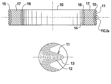
Fig. 2 is a cross-sectional view of a multiple ribbed
pulley made using the inventive process. Fig. 2a is a detail
of Fig. 2. The improved grain structure in the rib area is
shown in Fig. 2a. The flow forming process causes a grain
structure portion 12 in an outer portion of the body 10 to be
oriented substantially parallel to a rib surface 13. The
density of the material in the outer portion 15, including the
ribs, is substantially increased while substantially
eliminating porosity. The density of the ribs and outer
portion 15 approaches 100% of the metal density. Therefore,
portion 15 comprises an 8-15% density increase over the
density of the PM body portion 17 not subjected to flow
forming.
The flow forming improves the strength of the part by
forming the grains of the steel versus cutting them as occurs
during machining. Furthermore, flow forming creates work
hardening, which improves the mechanical properties of the
material by 50% or more. The forces of forming, above the
yield strength and below the ultimate tensile strength (the
plastic zone), cause the organized metal crystal arrays to be
broken, creating "dislocations". Atoms of metal are at a
higher exited energy level in the dislocated areas. The atoms
excitation is reflected in the material as improved mechanical
properties, including greater strength for the part. As the
sintered metal flow occurs in the plastic state, all the pores
existing in the sintered metal created by the PM process or by
casting are closed and disappear practically. Mechanical
properties such as yield strength, ultimate tensile strength,
and hardness are also an indication of material strength
improved by the inventive process.
The internal diameter surface 14 of the disk, see Fig. 2,
can be spun in an internal spinning operation (known in the
art of sheet metal spinning) to densify the material in inner
portion 16 giving portion 16 more dimensional accuracy as
well. Any desired profile can be spun into surface 14, for
11
CA 02531435 2006-01-04
WO 2005/009655 PCT/US2004/023185
example a curvilinear form for mechanically engaging and
accepting a damper elastomeric member (not shown). An
internal diameter surface 14 so flowed can receive a bearing,
for example. As with portion 15, flow formed portion 16
comprises an 8-15% density increase over the density of the PM
body portion 17 not subjected to flow forming.
The depth or thickness of portion 15 and portion 16 is a
function of the forming pressures used during spinning and can
be adjusted to suit the needs of a particular design. It
should be understood that although certain references herein
are to a `surface' the effects of spinning the body extend to
a depth within the body depending upon the pressures used
during the spinning flow forming process, thereby creating a
volume having a greater density in the spun portion as opposed
to the portion not subjected to flow forming.
Flow forming narrows dimensional tolerances to more
highly accurate levels while densifying all or selected
portions of the part, all without need for finish machining.
Both internal and external surface spinning can be performed
simultaneously in one spinning machine, if required. Of
course, finish machining of any desired surface may be
performed if required as well.
The foregoing description is made for purpose of
illustration only and is not intended to limit the scope of
the invention which is to be determined by the appended
claims. Further, although a form of the invention has been
described herein, it will be obvious to those skilled in the
art that variations may be made in the construction and
relation of parts without departing from the spirit and scope
of the invention described herein.
12