Note: Descriptions are shown in the official language in which they were submitted.
CA 02531509 2006-O1-06
WO 2005/008004 PCT/US2004/022219
CABLE LOCK AND METHOD
Field of the Invention
The present invention relates generally to locking apparatuses and methods,
and
more particularly, to cable locks and locking methods.
Background of the Invention
Many varieties of locking devices exist in today's marketplace and are used to
lock
a variety of different devices or items. Some of these conventional locking
devices are
cable locks. Such conventional cable Iocks typically include a housing and a
cable having
one end connected to the housing and a second end insertable into and locked
to the
housing. These conventional cable locks typically use a wire cable having a
plurality of
metal wires twisted around each other to form a single cable. Wire cables
typically have a
spiraled exterior surface created by the twisting of the wires. Conventional
cable locks
typically have an unlocked state in which a free end of the cable is not
inserted into the
housing, and a locked state in which the free end of the cable is inserted
into the housing
and is locked thereto by an engaging member or locking member positioned
within the
housing.
Through patience, skill, and (at times) significant resources and ingenuity,
thieves
have found one or more manners to defeat virtually every cable lock in the
marketplace.
In many applications suitable for cable locks, success for a thief lies not in
the ability to
circumvent a cable lock (which can readily be done simply with cable cutters,
liquid
nitrogen and a hammer, or in other manners employing brute force), but to do
so in an
undetected manner. By circumventing a cable lock without being detected,
efforts of
security personnel to detect the theft in a timely manner and to determine
when and/or
where the theft occurred is compromised. Many different manners of
circumventing
conventional cable locks have been employed throughout the years, some of
which will
now be described fox purposes of illustration and example.
Some conventional cable Iocks define an inlet aperture in a wall of the
housing to
allow insertion of the cable into the housing. Such inlet apertures are
typically round.
When a cable (such as a wire cable) is inserted into the inlet apertures, gaps
axe present
between the cable and the edge of the inlet aperture due to the gaps created
between the
spirals of the cable. Such gaps provide a place through which thieves can gain
entry into
the internal elements of the cable lock (e.g., with picks and other tools) to
potentially
CA 02531509 2006-O1-06
WO 2005/008004 PCT/US2004/022219
2
unlock the cable lock. By unlocking the cable lock in this manner, the thieves
can re-lock
the cable lock after a theft to reduce the chances that the theft will be
quickly detected.
Some conventional cable locks include engaging members or locking members
(e.g., balls, pins, discs, tabs, and the like) that are retained within the
housing of the cable
locks and grip the cable received therein. Such locking members grip the cable
and
provide resistance to cable withdrawal out of the housing in a direction
opposite that of
cable insertion. Thieves have bypassed these types of conventional cable locks
by
repeatedly twisting the cable with force in clockwise and counter-clockwise
directions in
order to create slippage between the cable and the engaging or locking members
until the
cable is completely removed from the housing in the insertion direction. In
this manner,
the cable lock can be re-locked after a theft to delay detection of the theft.
Many conventional cable locks include housings defining an internal cavity
having
an enclosed end and an open end through which the internal components of the
cable lock
are inserted into the cavity during manufacturing of the cable lock. The open
end is sealed
1 S off by positioning an end cap in the open end of the housing and by
crimping the housing
around the end cap. Such crimping of the housing secures the end cap in place
in the open
end of the housing. However, crimping the housing to around the end cap can
create gaps
between the edge of the end cap and the housing through which picks and other
tools can
be inserted to tmlock the lock. In some cases, thieves position a tool or
machine within the
gap and pry the end cap out from the open end of the housing or uncrimp the
open end of
the housing in order to remove the end cap from the open end of the housing.
In either
case, access is thereby provided to the internal components of the cable lock.
To delay
detection of a theft, the tlueves can replace the end cap in the open end of
the housing and
can re-crimp the housing using a tool or machine to once again secure the end
cap in place.
Conventional cable locks typically employ a cable permanently secured with
respect to the housing and having a free end for insertion into the housing as
described
above. In order for the first end of the cable to be permanently secured with
respect to the
housing, some conventional cable locks have a projection or other body portion
connected
'or integral with the housing. This projection or other body portion has an
aperture through
which the cable is passed, after which time the projection or other body
portion is crimped
to secure the cable with respect to the housing. However, thieves have
bypassed such
cable locks by cutting the cable, using a machine or tool (e.g., a drill) to
remove the cut
cable from the aperture, inserting a new cable, and re-crimping the new cable
in the
aperture.
CA 02531509 2006-O1-06
WO 2005/008004 PCT/US2004/022219
3
By using the methods discussed above and others on conventional cable locks,
it is
often difficult to identify that the locks have been bypassed. In some
applications (such as
for trailers, cargo containers, and other mobile cargo storage units used to
move cargo),
the popular use of conventional cable locks is exacerbated due to the added
difficulty in
S identifying where the theft took place during transit. Having more prompt
information
indicating that a theft has occurred could more easily lead law enforcement
agencies to the
thieves and the stolen goods.
In light of the above problems and issues (as well as others known to those in
the
art but not discussed herein), an improved cable lock and locking method would
be
welcome in the art.
Summarx of the Invention
Some embodiments of the present invention provide a cable lock having a cable
with a cross-sectional shape and a radius varying at different circumferential
positions of
the cross-sectional shape, a housing defining an internal cavity therein, and
a wall
positioned to block access into the cavity of the housing, wherein the wall
has an aperture
defined therethrough with a radius varying at different circumferential
positions of the
aperture, and at least a portion of the cross-sectional shape of the cable has
a shape
complementary to the shape of the aperture to inhibit ingress of an object
into the internal
cavity of the housing between the cable and the wall.
In some embodiments, a method of locking a cable lock is provided in which an
end of a cable is inserted into and through an aperture of a wall, wherein the
cable has a
cross-sectional shape with a radius varying at different circumferential
positions of the
cable, wherein the aperture has a cross-sectional shape with a radius varying
at different
circumferential positions of the aperture, and wherein the cable and aperture
have
complementary shapes. The method also includes inserting an end of the cable
into and
through a housing in a first direction, preventing movement of the cable
through the
housing in a second direction substantially opposite the first direction, and
blocking
ingress of objects into the housing along a surface of the cable through the
aperture by the
complementary shapes of the cable and aperture.
In another aspect of the present invention, a cable lock is provided, and has
a body
with a first portion defining a housing having an internal cavity and a second
portion
having an apertuxe therethrough and a visible indicator thereon, wherein the
visible
indicator is deformable under force applied to the second portion. The cable
lock also has
CA 02531509 2006-O1-06
WO 2005/008004 PCT/US2004/022219
4
a cable retained within the aperture in the second portion of the body,
wherein the cable
has an end insertable into the internal cavity of the housing to lock the
cable lock.
Some embodiments of the present invention also provide a method of assembling
a
cable lock, including providing a body having a first portion defining a
housing and a
second portion, forming visible indicia upon the second portion of a body,
wherein the
visible indicia is deformable under force applied to the second portion of the
body,
inserting a cable into an aperture in the second portion of the body, and
securing the cable
within the aperture in the second portion of the body.
The present invention according to some embodiments also provides a cable lock
having a housing and a cable insertable into the housing in a first direction,
wherein the
cable has a locked state within the housing in which the cable is movable with
respect to
the housing in the first direction but is restrained against movement with
respect to the
housing in a second direction substantially opposite the first direction, and
wherein the
cable is rotatable relative to the housing when in the locked state.
Also, the present invention according to some embodiments further includes a
method of locking a cable lock, including inserting a cable into a housing in
a first
direction, feeding the cable into the housing to a locked position in which
the cable is
restrained from motion in a second direction substantially opposite the first
direction, and
rotating the cable with respect to the housing in the locked position of the
cable.
~ther features and advantages of the present invention will become apparent to
those skilled in the art upon review of the following detailed description,
claims, and
drawings.
Brief Description of the Drawings
The present invention is further described with reference to the accompanying
drawings, which show exemplary embodiments of the present invention. However,
it
should be noted that the invention as disclosed in the accompanying drawings
is illustrated
by way of example only. The various elements and combinations of elements
described
below and illustrated in the drawings can be arranged and organized
differently to result in
embodiments which are still within the spirit and scope of the present
invention.
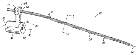
Fig. 1 is a perspective view of a trailer utilizing a cable lock according to
an
exemplary embodiment of the present invention;
Fig. 2 is a perspective view of the cable lock shown in Fig. 1, shown in a
locked
State; .
CA 02531509 2006-O1-06
WO 2005/008004 PCT/US2004/022219
Fig. 3 is a perspective view of the cable lock shown in Fig. 1, shown in an
unlocked state;
Fig. 4 is an exploded perspective view of the cable lock shown in Fig. 1;
Fig. 5 is a cross-sectional view of the cable employed in the cable lock shown
in
5 Fig. 1, taken along line 5-5 of Fig. 3;
Fig. 6 is a front view of a wall of the cable lock shown in Fig. 1;
Fig. 7 is a perspective view of the wall shown in Fig. 6;
Fig. ~ is a partial side view of the cable lock shown in Fig. 1;
Fig. 9 is a partial end view of the cable lock shown in Fig. 1;
Fig. 10 is a cross-sectional view taken along line 10-10 in Fig. 9, with the
cable
lock shown in an unlocked state;
Fig. 11 is a cross-sectional view similar to the cross-sectional view shown in
Fig.
10, shown with the cable lock in a locked state;
Fig. 12 is a partial perspective side view of the cable Iock shown in Fig. 1;
Fig. 13 is a perspective view of a cable lock according to another embodiment
of
the present invention,~shown in a locked state;
Fig. 14 is a cross-sectional view taken along line 14-14 in Fig. 13, shown
with the
cable lock in a locked state.
before any embodiments of the invention are explained in detail, it is to be
understood that the invention is not limited in its application to the details
of construction
and the arrangement of components set forth in the following description or
illustrated in
the following drawings. The invention is capable of other embodiments and of
being
practiced or of being carried out in various ways. Also, it is to be
understood that the
phraseology and terminology used herein is for the purpose of description and
should not
be regarded as limiting. The use of "including," "comprising," or "having" and
variations
thereof herein is meant to encompass the items listed thereafter and
equivalents thereof as
well as additional items. Unless limited otherwise, the terms "connected,"
"coupled," and
variations thereof herein are used broadly and encompass direct and indirect
connections
and couplings. In addition, the terms "connected" and "coupled" and variations
thereof
are not restricted to physical or mechanical connections or couplings.
Detailed Description
Referring to Fig. 1, a cable lock 20 according to an exemplary embodiment of
the
present invention is illustrated in combination with a vehicle trailer 24.
Like other cable
CA 02531509 2006-O1-06
WO 2005/008004 PCT/US2004/022219
6
locks, the cable lock 20 can be employed to secure a wide variety of items and
areas, such
as, for example, trailers and cargo containers transportable by a truck, boat,
train, etc.,
other types of containers, doors, gates, machinery, equipment, or any other
item or device
that can be locked or otherwise secured with a cable lock. The cable lock 20
can be
employed in conjunction with any type of latch to secure the latch from
release. By way
of example only, and as illustrated in Fig. 1, a cable lock 20 can be used in
combination
with a latching device 2i~ mounted on a vehicle trailer 24 to lock one or more
doors of the
trailer 24. Alternatively, the cable lock 20 can be used to secure items and
areas in other
manners, such as by wrapping around handles of doors, passing a cable of the
cable lock
through apertures or other features of the items to be secured, and the like.
With reference to Figs. 2-5, some embodiments of the cable lock 20 according
t~
the present invention include a body 32 and a cable 36 connected to the body
32. The
cable lock 20 has a locked state or locked condition (see Fig. 2) in which the
cable 36 is
inserted into the body' 32, and an unlocked state or unlocked condition (see
Fig. 3) in
which the cable 36 is not inserted into the body 32. In some embodiments, the
cable 36 is
inserted substantially along an insertion axis 40 passing into and/or through
the body 32
(e.g., see Figs. 3-4).
The body 32 includes a housing 44 defining a cavity 4~ therein within which
internal components of the cable lock 20 are housed. The housing 44 can have
any shape
desired, including without limitation cubical, cubeoidal, polyhedral,
prismatic, spherical,
elliptical, frusto-conical, and frusto-pyramidal. In the illustrated exemplary
embodiment,
the housing 44 is substantially cylindrical in shape.
The housing 44 can have at least one open end into which internal components
of
the cable lock 20 can be received during assembly. In some embodiments, only
one end of
the housing 44 is open, while an opposite end is substantially closed by an
end wall of the
housing 44. In other embodiments, both ends of the housing 44 are open, and
can be
substantially closed by separate elements of the cable lock 20 (such as by two
walls each
similar to the wall 60 in the illustrated exemplary embodiment). In the
illustrated
embodiment, the housing 44 is substantially cylindrical and has an open end 56
and a
closed end 52 defined by a wall of the housing 44.
An inlet 60 can be defined in an enclosed end 52 of the housing 44 for passage
of a
cable 36 into andlor through the housing 44. .Alternatively, the inlet 60 can
be defined in a
separate element of the cable lock 20 for this same purpose. In either case,
the inlet 60 can
be substantially aligned with an insertion axis 40 of the housing 44
(described above). In
CA 02531509 2006-O1-06
WO 2005/008004 PCT/US2004/022219
7
the illustrated embodiment, the inlet 60 is substantially circular in shape.
However, the
inlet 60 can have any other shape desired, such as, for example, triangular,
rectangular,
trapezoidal, or any other polygonal shape, oval, irregular, and the like.
In some embodiments of the present invention, the body 32 also has another
portion t~ which the cable 36 is permanently attached. In this regard, the
body 32 can
have any shape capable of providing such an attachment location. For example,
the
housing 44 can have a portion 64 thereon or extending therefrom defined by a
lug, boss,
post, block, or other element to which the cable 36 is permanently attached.
In some
embodiments, the housing 44 itself can be shaped to provide a permanent
connection point
of the cable 36. ~ne body shape is illustrated in the figures by way of
example only.
Specifically, the illustrated body 32 has a housing 44 and a portion 64
extending from the
housing 44 and defining an aperture 6~ therein in which the cable 36 is
received. The
cable 36 can be permanently secured to this portion 64 of the body 32 in a
number of
manners, including without limitation by welding, brazing, soldering, and the
like (some
connection manners suitable with or without the use of an aperture 68 through
which the
cable 36 passes as will be appreciated by one having ordinary skill in the
art). In the
illustrated exemplary embodiment, the cable 36 is permanently secured within
the aperture
68 of the body 32 by crimping the portion 64 of the body 32 defining the
aperture 6~,
thereby compressing and securing the cable 36 within the cable aperture 6~.
Accordingly,
this portion 64 of the body 32 in some embodiments can be referred to as a
crimp portion
64 of the body 32. In some embodiments, one or more visual indicators 72 can
be located
on each side of the crimp 64 for indicating whether the portion 64 of the body
to which the
cable 36 is permanently secured has been tampered with (discussed in greater
detail
below).
In those embodiments in which the cable 36 is permanently secured to a
separate
portion 64 of the body 32 (apart from the housing 44) this portion can be
connected to the
housing 44 in a variety of different manners, such as, for example by welding,
brazing,
crimping, or soldering, by one or more conventional fasteners, by inter-
engaging elements
on the portion 64 and the housing 44, by a snap-fit, press-fit, or threaded
connection
between the portion 64 and the housing 44, and the like. The housing 44 and
the body
portion 64 to which the cable 36 is permanently secured can also be integrally
formed,
thereby making the body 32 a single integral piece.
As used herein and in the appended claims, the term "cable" means any
elongated
item that can be permanently connected at a point along its length (e.g., a
first end as
CA 02531509 2006-O1-06
WO 2005/008004 PCT/US2004/022219
8
shown in the exemplary illustrated embodiment) to the body 32 as discussed
above and a
second end insertable into and through the housing 44 to place the cable lock
in the locked
state. In this regard, the cable is permanently connected at least to the
extent that the cable
is secured to the body 32 and cannot be removed without the use of tools cr
machinery or
without damage or destruction of the cable 36, body 32, or other lock
component(s). In
the illustrated embodiment, the cable 36 is a metallic bendable wire cable and
consists of a
plurality of metallic wires wound or twisted about a longitudinal cable axis
74 (when the
cable is in an unbent state) to give the cable 36 a spiral shape.
Alternatively, the cable 36
can be other type of elongated item capable of performing the same functions
described
herein, such as, for example a rope, a chain, a rod, bar, or strip bent in a
shape permitting
rod connection to the body 32 and rod insertion within the housing 44, a
flexible tape,
wire, rod, bar, strip, or other flexible elongated element permitting the same
connections,
and the like. The cable 36 can be made of any material desired, including
without
limitation any suitable type of metal, plastic or composite material, fabric,
and the like
(keeping in mind that an important function of the lock 20 in some
applicati~ns is not
necessarily to prevent circumvention of the lock 20, but to indicate when the
lock 20 has
been tampered with).
In some embodiments of the present invention, the cable 36 has a cross-
sectional
shape having a radius that varies at different circumferential positions of
the cross-
sectional shape (see Fig. 5). In other words, the cross-sectional shape ~f the
cable 36 is
not round in such embodiments. Tn some embodiments, this varying radius is a
product of
the type of cable employed. For example, the mufti-strand wound metal cable
utilized in
the illustrated embodiment defines a non-constant radius. Alternatively, the
cable 36 can
have a cross-section of other shapes, such as, for example substantially
round, oval, or
elliptical, substantially triangular, rectangular, trapezoidal, or having any
other polygonal
shape (with or without curved sides and/or corners), irregular, and the like.
In this regard,
the term "radius" and variations thereof herein and in the appended claims is
used broadly
and refers to the distance between a center of any shape and the edge of that
shape at any
given circumferential location of the shape, and does not indicate or imply
the shape of the
cross-section. In other words, as used herein and in the appended claims, a
square (for
example) can have a "radius" at any given location on the edge of the square
defined by
the distance between the center of the square and that location. Also, the
term
"circumference" and variations thereof used herein and in the appended claims
is used
broadly and refers to the external boundary or surface of any figure, object,
or shape, and
CA 02531509 2006-O1-06
WO 2005/008004 PCT/US2004/022219
9
does not indicate or imply any particular shape. Accordingly as used herein
and in the
appended claims, a square (for example) has a "circumference" defined by the
periphery
of the square.
In some embodiments, the cable 36 an end of the cable 36 is tapered or is
otherwise reduced in size to ease insertion of the cable 36 into the housing
44. For
example, the cable 36 in the illustrated exemplary embodiment has an end that
is frusto-
conically shaped. This end of the cable 36 can be frusto-conically shaped in a
variety of
manners, such as, for example, by grinding the end of the cable to generate
heat sufficient
to melt the cable into the desired shape (e.g., melting the ends of the
strands in a multi-
strand wound metal cable), by melting or fusing the end of the cable 36 in any
other
manner, by connecting a separate frusto-conical shaped component t~ the second
end
(such as by welding, brazing, soldering, crimping, gluing, and the like), etc.
Insertion of
the cable 36 into the housing 44 will be discussed in greater detail below.
With continued reference to Figs. 2-5, some embodiments of the lock 20 also
include a spacer 76 positioned within the cavity 48 at an end of the housing
44 into which
the cable 44 is inserted as will be described in greater detail below. In the
illustrated
embodiment, the spacer 76 is made of a low friction material and/or has
polished, waxed
or otherwise smooth surfaces for reasons that will become apparent herein. The
spacer 76
has an aperture 80 therethrough and in the illustrated embodiment is
positioned adjacent
the closed end 52 of the housing 44 (although the spacer 80 could instead be
located at
either end of the housing 44 depending upon the arrangement of internal
components as
described in greater detail below). The aperture 80 of the spacer 76 can be
substantially
aligned with the insertion axis 40 of the housing 44. In the illustrated
embodiment, the
spacer 76 is substantially round and matches the internal cross-sectional
shape of the
housing 44. However, the spacer 76 can have a variety of other cross-sectional
shapes that
can (but do not necessarily) match the shape of the cavity 48. By way of
example only,
the spacer 76 can be triangular, oval, rectangular, can have am irregular
shape, or can have
any other polygonal or non-polygonal shape desired. Also in the illustrated
embodiment,
the inlet 60 and the spacer aperture 80 are substantially the same size and
are substantially
the same shape. However, the inlet 60 and the spacer aperture 80 can be sized
differently
(i.e., the inlet 60 being larger than the spacer aperture 80 or vice versa),
and can have
different shapes while still falling within the spirit and scope of the
present invention.
Refernng now to Figs. 4, 6, and 7, the body 32 also includes a wall 84
positioned
within the cavity 48. Zn those embodiments employing a spacer 76 as described
above, the
CA 02531509 2006-O1-06
WO 2005/008004 PCT/US2004/022219
wall 84 can be located adjacent the spacer 76 (which can be positioned between
the wall
84 and the end 52 of the housing 44). An aperture 88 is defined through the
wall 84, and
in some embodiments is substantially aligned with the insertion axis 40 of the
housing 44.
In the illustrated exemplary embodiment, the wall aperture 88 has a plurality
of grooves 92
5 (see Fig. 7) defined in the periphery of the aperture 88. These grooves 92
can be
dimensioned and shaped to complement the cross-sectional shape of the cable
36. In other
embodiments, the aperture 88 has any other edge shape desired, including
without
limitation round, oval, triangular, rectangular, trapezoidal (or any other
polygonal shape),
irregular, and other shapes, and can also be shaped to complement any cross-
sectional
10 shape of any cable 36.
Because many mufti-strand wound metal cables have wires that are twisted about
an axis of the cable 36 (in a helical fashion), the grooves 92 in the wall
aperture 88 can be
helically shaped to match such cables 36, as best showxn in Figs. 6 and 7.
Spiraled grooves
92 therefore complement spirals 96 of the cable 36 when the cable 36 is
inserted through
the wall aperture 88 (discussed in greater detail below). The spiraled strands
96 of the
cable 36 can therefore be received within the spiral grooves 92 defined in the
edge of the
wall aperture 88 to form a tight engagement between the spiraled strands 96 of
the cable
36 and the wall 84. Such a spiraled shape can also be employed for any other
aperture
shape desired in order to compliment the shape of any cable.
dewed from a front or rear of the wall 84, the spiral grooves 92 of the wall
aperture 88 provide the wall aperture 88 with a radius varying at different
circumferential
locations of the wall aperture 88 to complement a similar cross-sectional
shape of the
cable 36. In other words, the wall aperture 88 in the illustrated exemplary
embodiment
appears to have a scalloped edge as viewed from a front or rear of the wall
84.
Alternatively, and as mentioned above, the wall aperture 88 can have any other
shape
desired to (in some embodiments) compliment or match the cross-sectional shape
of the
cable 36 passed therethrough, thereby forming form a closer engagement between
.the
cable 36 and the wall 84 when the cable 36 is inserted through the wall
aperture 88.
With particular reference to Fig. 4, the body 32 further includes a locking
assembly
100 operable to engage the cable 36 and to place the cable lock 20 in a locked
state. The
locking assembly 100 allows the cable 36 to be inserted therethrough in a
first direction,
(from the inlet 60 to the open end 56 of the housing 44 in the illustrated
exemplary
embodiment), and prevents the cable 36 from being pulled out of the housing 44
in a
second direction opposite the first direction. In some embodiments, the
locking assembly
CA 02531509 2006-O1-06
WO 2005/008004 PCT/US2004/022219
11
100 is separate from the housing 44 and has parts operable to move relative to
the housing
44 in a rotational and/or axial manner (discussed in greater detail below).
The exemplary locking assembly 100 illustrated in the figures includes a
locking
assembly housing 104 defining a cavity 108 therein, a carriage 112 positioned
within the
housing 104, a spring 116, and a locking assembly end cap 120. The locking
assembly
housing 104 defines an inlet 124 in one end thereof. The inlet 124 of the
locking assembly
housing 104 can be substantially aligned with the insertion axis 40. The
cavity 108 of the
illustrated locking assembly housing 104 has a diameter that increases away
from the inlet
124 of the locking assembly housing 104. Although a number of different
internal shapes
of the locking assembly housing 104 having such an increasing diameter can be
employed
in the present invention, in some embodiments the cavity 108 of the loeking
assembly
housing 104 has a portion 128 with a substantially constant diameter and
another portion
132 with a gradually narrowing diameter (see Figs. 10 and 11) as just
described. In other
embodiments, the locking assembly housing 104 has no portion with a
substantially
constant internal diameter.
A carriage aperture 152 is defined through the carriage 112, can be aligned
with
the insertion axis 40 of the housing 44, and is shaped and dimensioned to
pennit the cable
36 to be passed therethrough. The carriage 112 of the locking assembly 100
f~xnctions to
hold one or more cable grips or gripping elements, such as balls, plates,
pins, tabs, discs,
within the locking assembly 100. Such support for gripping elements can be
provided in a
number of different manners, each of which falls witlun the spirit and scope
of the present
invention. ~y way of example only, the carriage 112 in the illustrated
embodiment has
includes a grip support 136 shaped to support one or more grips 140 (in the
form of balls
140) therein. This exemplary carriage 112 also has a spring retainer 144
shaped to retain
an end of the spring 116. Although the locking assembly 100 can have any
number of
gripping elements (e.g., balls 140), the illustrated locking assembly 100 has
four balls 140
retained within the carriage 112. The balls 140 are supported within
receptacles 148
defined in the carriage 112 and in some embodiments axe freely moveable
therein. The
balls 140 can be retained in place with respect to the carriage in any other
manner, such as
by being received within a circumferential groove of the carriage 112, by
being received
within one or more slots or other apertures in the carriage 112, and the like.
If employed, the spring retainer 144 of the carriage 112 can be smaller in
diameter
than the grip support 136 and can be shaped and sized to receive an end of the
spring 116
therearound. Alternatively, the spring 116 can be received within a groove,
wall, or other
CA 02531509 2006-O1-06
WO 2005/008004 PCT/US2004/022219
12
feature of the carriage 112, or can be positioned with respect to the carriage
112 in any
other manner permitting the spring 116 to bias the carriage 112 toward the
inlet 60 while
permitting passage of the cable 60 into and through the housing 44. The spring
116
engages the carnage 112 and biases the carriage 112 in a direction toward the
inlet 60 of
the housing 44.
In the illustrated embodiment, the spring 116 is a coil spring. Alternatively,
the
spring I 16 can be other types of springs, such as, for example a leaf spring,
a Belville
washer, a resilient bushing, any other type of biasing member that can bias
the carriage
112 toward the inlet 60 of the housing 44. Any number of springs can be
employed to bias
the carnage 112 as described above.
The locking assembly end cap 120 is positioned at the opposite end of the
carriage
112 from the inlet 124, and can be attached to the carnage 112 in any manner,
such as by
one or more fasteners, by crimping the end cap 120 as shown in the illustrated
embodiment, by welding, brazing, soldering, crimping, or gluing, by a snap-fit
or
I S interference fit with the end of the carriage 112, or in any other manner.
The end cap 120
can close off the cavity 108 with the exception of an end cap. aperture .156
therethrough for
passage of the cable 36, and can be aligned with the insertion axis 40 of the
housing 44.
The end cap 120 can also provide a surface against which the spring 116 can
press.
However, it should be noted that in alternative embodiments, the end cap 120
is not
employed, end the spring 116 instead engages the end wall 60 of the housing
44.
Deferring now to Figs. 4 and 8-9, the housing 44 of the illustrated exemplary
embodiment further includes an end cap 160 secured at the open end 56 of the
housing 44
to close off the cavity 48 (with the exception of an aperture 164
therethrough). The end
cap 160 can be secured to the housing 44 in any manner, including those
described above
with reference to the connection between the end cap 120 and the carriage 112.
In the
illustrated embodiment, the housing 44 is crimped or rolled over and around
the edges of
the end cap 120 to eliminate gaps between the housing 44 and the end cap 160.
In some
embodiments, the housing 44 extends over and slightly past the end cap 160,
and is
crimped or rolled over the periphery of the end cap 160 such that an annular
portion of the
external face of the end cap 160 is covered by the edge of the housing 44. An
end cap
aperture 164 is defined through the end cap 160, and can be substantially
aligned with the
insertion axis 40 of the housing 44.
With particular reference to Fig. 10, the unlocked state of the exemplary
cable lock
20 illustrated in the figures will now be described. In the unlocked state,
the cable 36 is
CA 02531509 2006-O1-06
WO 2005/008004 PCT/US2004/022219
13
not inserted into and through the body 32. The carriage 112 is biased forward
(toward the
inlet 60 of the housing 44) by the spring 116, and the balls 140 engage the
narrowing
diameter portion 132 of the cavity 108 toward the locking assembly inlet 124.
In this
forward condition, the balls 140 are biased inward toward each other by the
narrowing
diameter portion 132, and are closely spaced together.
With particular reference to Fig. 1 l, the locked state of the exemplary cable
lock
20 illustrated in the figures will now be described. To move the cable lock 20
from the
unlocked state to the locked state, the free end of the cable 36 is inserted
into the body 32
(e.g., the housing 44 in the illustrated embodiment) along the insertion axis
40. This end
of the cable 36 is inserted through the inlet 60, the spacer aperture 80 and
the wall aperture
88. Upon insertion of the cable 36 into the wall aperture 88, the spirals 96
of the cable 36
are received in engagement within the spiral grooves 92 of the wall aperture
88. Such
close engagement inhibits ingress of an object (such as a pick or other tool)
further into the
cavity 48 of the housing 44 between the cable 36 and the wall 84. Also, by
virtue of the
spiral engagement between the cable 36 and the wall 84, the wall 84 rotates
with the cable
36 as the cable 36 is inserted further along the insertion axis 40. In other
embodiments
not employing such a relationship between the cable 36 and the wall 84 (i.e.,
spiraled
grooves or other features), the wall 84 need not rotate during insertion of
the cable 36.
Upon further insertion of the cable 36, the cable is received within the
locking
assembly 100 and, particularly, into the carriage 112 through the locking
assembly inlet
124. The cable 36 engages the balls 140 and pushes them outward against (if
not already
engaged) the narrowing diameter portion 132 of the carriage 112. The
narrowness of the
cavity diameter engaged by the balls 140 prevents the balls 140 from moving
sufficiently
outward away from the cable 36 to allow the cable 36 to pass thereby.
Accordingly,
applying an insertion force to the cable 36 sufficient to overcome the~bias of
the spring
116 will move the carnage 112 toward the end cap 120 and compress the spring
116.
Rearward movement of the carnage 112 brings the balls 140 into engagement with
a
larger-diameter portion of the cavity 108, thereby allowing the balls 140 to
move further
outward and allowing the cable 36 to pass the balls 140. The cable 36 then
passes through
the end cap aperture 156 of the locking assembly 100 and finally exits the
housing 44
through the end cap aperture 164. In this state, the spring 116 biases the
carnage 112
toward the inlet 124 of the lock assembly housing 104 and toward the narrowing
diameter
portion 132 of the housing 104. The carriage 112 comes to rest when the balls
140 are
CA 02531509 2006-O1-06
WO 2005/008004 PCT/US2004/022219
14
sufficiently compressed between the narrowing diameter portion 132 of the
housing 104
and the cable 36, thereby pinching the cable 36 between the balls 140.
During insertion of the cable 36 into and through the body 32, several types
of
rotation can occur depending upon the types and arrangements of elements
employed in
the lock 20 as described above. First, spiral engagement (if employed) between
the wall
84 and the cable 36 causes the wall 84 to rotate as the cable 36 is passed
through the body
32. The spacer 76 (if employed) can be rotatable relative to the housing 44
and is
positioned between the wall 84 and the end 52 of the housing 44 to ease
rotation of the
wall 84 and to prevent engagement between the wall 84 and the end 52 of the
housing 44,
thereby reducing friction upon the wall 84 that could otherwise reduce the
ability of the
wall 84 to rotate. Secondly, the locking assembly 100 can rotate relative to
the housing 44
during insertion of the cable 36 through the body 32. Notation of the locking
assembly
100 may be caused by rotational forces exerted on the balls 140 by the spirals
96 of the
cable 36. Thirdly, the cable 36 and balls 140 can rotate relative to the
housing 104 of the
locking assembly.I00. The rotational forces exerted by the spirals 96 of the
cable 36 upon
the balls 140 can be entirely absorbed by the balls 140 as they rotate about
the cable 36
within the housing 104..
With continued reference to Fig. 1 I, the locking assembly 100 prevents the
cable
36 from being pulled through the housing 44 in a direction opposite the
direction of cable
insertion. As mentioned above, the balls 140 are compressed between the cable
36 and the
housing 104 of the locking assembly 100 (such as between the cable 36 and the
narrowing
diameter portion 132 of the housing 104), thereby pinching the cable 36 with
the balls 140.
Therefore, a force applied to the cable 36 in a direction opposite the cable
insertion
direction described above will apply a force on the locking assembly 100 in
the direction
opposite the cable insertion direction, will bias the balls I40 against the
narrowing
diameter portion 132 of the housing 104, and will therefore bias the balls 140
into tighter
engagement with the cable 36. This engagement between the cable 36 and the
balls 140 is
sufficient to prevent the cable 36 from being pulled out of the body 32.
A number of the features and elements described above significantly increase
the
difficulty of picking or otherwise bypassing the lock of the present
invention. Examples
of how some of these features generate this result will now be discussed. In
this regard, it
should be noted that any of the features described above or hereafter can be
employed
alone or in combination as desired.
CA 02531509 2006-O1-06
WO 2005/008004 PCT/US2004/022219
Referring back to Figs. 6-7 and 1 l, the complimentary shapes of the cable 36
and
wall aperture 88 (if employed) can prevent picks or other tools from
penetrating past the
wall 84 and further into the housing 44 in an effort to manipulate and
possibly unlock the
cable lock 20. In those cases where features of the wall aperture 88 are
spiraled along the
thickness of the wall 84 as described above, the complementary spiral shapes
of the wall
84 and cable 36 further inhibit ingress of an object into the cavity 108 of
the locking
assembly 100 between the cable 36 and the wall 84. In addition, by enabling
the wall 84
to rotate with respect to the housing 44, the ability of a thief to damage the
wall 84 by
repeatedly twisting the cable 36 is lessened or eliminated.
10 Another feature that inhibits a thief from bypassing the cable lock 20 is
the
engagement between the balls 140 and the cable 36. In some embodiments of the
present
invention, rotation of the cable 36 causes the balls 140 (or other gripping
elements as
described above) to rotate with the cable 36. Although the balls 140 do not
roll by virtue
of their firm engagement with the cable 36, the balls 140 can slide against
the internal
15 surface of the lock assembly housing 104 (i.e., orbiting the balls 104
about the insertion
axis 40 of the housing 44). Such movement prevents the ability of a thief to
loosen the
grip of the lock 20 upon the cable 36 by rotating the cable 36 with force from
outside of
the housing 44.
Another feature of the cable lock 20 that inhibits bypassing of the lock 20 is
the
independent movement of the locking assembly 100 relative to the housing 44.
in some
embodiments of the present invention. In such embodiments, the housing 104 of
the
locking assembly 100 can rotate freely within and with respect to the housing
44 of the
cable lock 20. Rotation of the cable 36 therefore causes the entire locking
assembly 100 to
rotate with the cable 36 relative to the housing 44, thereby inhibiting any
slippage between
the cable 36 and the locking assembly 100. In some embodiments, this relative
rotation
between the housings 104, 44 can be employed in conjunction with the relative
movement
between the balls 40 and the locking assembly housing 104 described above.
Referring back to Figs. 8-9, the manner in which the end cap 160 of the
illustrated
exemplary embodiment is connected to the housing 44 also inhibits bypassing of
the cable
lock 20. As mentioned above, the housing 44 is crimped over and around edges
of the end
cap 160 to eliminate externally accessible gaps between the housing 44 and the
end cap
160. Conventional cable locks have end caps connected to the housing in
manners (e.g.,
crimping a terminal edge of the housing to the periphery of the end cap) that
provide gaps
between end caps and the lock housing. Such gaps are externally accessible by
thieves,
CA 02531509 2006-O1-06
WO 2005/008004 PCT/US2004/022219
16
and provide a point at which a tool or machine can be inserted between the end
cap and the
housing in order to pry the end cap away from or off of the housing. With the
end cap
pried away from or off of the housing, the interior of the housing is
accessible and the
cable lock can be bypassed. Such gaps also provide a point at which an
expansion tool or
machine may engage the housing of the cable lock and unerimp the housing from
around
the end cap. With the housing uncrimped, the end cap can easily be removed
from the
housing. To hide the fact that such conventional locks have been compromised,
the end
cap can be repositioned in the open end of the housing and a tool or machine
can be
employed to re-crimp the end of the housing around the end cap to secure it to
the housing.
The lack of externally accessible gaps in the cable lock 20 of the present
invention
therefore inhibits such methods of bypassing the cable lock 20.
Referring now to Fig. 12, an indicator 72 (described above) on the body 32 is
represented by an ~mega by way of example only. Any letter, number, symbol,
graphics,
or combinations thereof can be located on the portion 64 of the body crimped
to secure the
cable 36 thereto. The indicator 72 can also have any size and color desired,
and can be
formed as a raised or relief portion of the body 32 (e.g., in a molding,
casting, or
machining operation), by printed, etched, or deposited matter on the body 32,
or in any
other mamzer desired. The indicator 72 is subject to damage by impact,
scraping, scuffing,
or other contact resulting from an attempt to re-crimp the body portion 64
upon a cable 36.
~y way of example only, indicators that axe defined in the material of the
body 32 (such as
raised material portions defined during molding or other manufacturing
operations) will
deform under pressure of re-crimping, thereby providing a visual indication
that the crimp
64 has been tampered with.
It should be understand that indicia 72 can be formed on other portions of the
cable
lock 20 to indicate whether the lock 20 has been tampering with. For example,
indicia 72
can be formed on the open end 56 of the housing 44 that is crimped around the
end cap
160. Such indicia 72 would indicate an effort to recrimp the housing 44 axound
the end
cap 160 as described above.
Referring now to Figs. 13 and 14, another exemplary embodiment of the cable
lock
20 according to the present invention is illustrated. With some exceptions
(described in
greater detail below), the cable lock 20 illustrated in Figs. 13 and 14 is
similar to the cable
lock 20 described above with reference to Figs. 1-12. Accordingly, reference
is made to
the above discussion regarding the structure, operation, and alternatives of
the cable lock
CA 02531509 2006-O1-06
WO 2005/008004 PCT/US2004/022219
17
20 illustrated in Figs. 13 and 14, wherein like elements and features of the
cable lock 20
illustrated in Figs. 13 and 14 have like reference numerals.
The cable lock 20 illustrated in Figs. 13 and 14 includes a housing 44 in
which the
closed end 52 and the open end 56 of the embodiment illustrated in Figs. 1-12
are reversed
in position. Specifically, the end cap 160 of the housing 44 defines the inlet
60
therethrough (rather than the closed end 52 of the housing), and the cable 36
is inserted
into the housing 44 through the inlet 60 defined in the end cap 160. In
addition, the spacer
76, wall ~4, and the locking assembly 100 are reversed in position within the
housing 44
compared to their positions and orientations in the embodiment of Figs. 1-12.
Accordingly, the spacer 76 is positioned adjacent the end cap 160, the wall S4
is
positioned adjacent the spacer 76 such that the spacer 76 is positioned
between the end cap
160 and the wall ~4, and the inlet 124 of the locking assembly 100 is adjacent
the wall 84.
The cable lock 20 illustrated in Figs. 13 and 14 provides an additional
advantage in
that the ability of thieves to open the lock 20 by attempting to remove the
end cap 160 is
substantially reduced., In particular, the location of the cable 36 received
within the inlet
60 of the housing reduces the ability of thieves to access the end cap 160
with tools and
other equipment in an effort to uncrimp or unroll the housing 44 from the end
cap 160.
The embodiments described above and illustrated in the figures are presented
by
way of example only and are not intended as a limitation upon the concepts and
principles
of the present invention. As such, it will be appreciated by one having
ordinary skill in the
art that various changes in the elements and their configuration and
arrangement are
possible without departing from the spirit and scope of the present invention
as set forth in
the appended claims. By way of example only, the features and elements of the
various
cable lock embodiments described above and illustrated in the figures can be
employed
regardless of whether the cable 36 is received entirely through the lock 20.
Specifically,
the housing 44 of the cable lock 20 need not necessarily have an aperture
through which
the end of the cable 36 can pass out of the housing 44 after being inserted
fully
therethrough. Instead, the cable 36 can terminate within the housing 44 while
still
permitting proper operation of the cable lock 20.