Note: Descriptions are shown in the official language in which they were submitted.
CA 02531587 2006-O1-05
WO 2005/008293 PCT/US2004/022197
SECURITY CHECKPOINT
BACKGROUND OF THE INVENTION
FIELD OF THE INVENTION
The invention relates to apparatus for coordinated screening of
passengers and packages at security checkpoints.
DESCRIPTION OF THE RELATED ART
Many different types of devices have been developed for
screening both people and parcels for weapons and other contraband.
These are used at airports, government buildings and other high security
locations. Additionally, security personnel employed at these locations have
been trained to identify certain personal characteristics that may trigger a
more detailed security investigation. For example, airline passengers may
be'subjected to a visual screening at the ticket check-in c~unter. The visual
screening will assess the demeanor and nervous state of the passenger, the
itinerary of the passenger, the method of payment for the ticket and in some
instances the ethnicity of the passenger. A ticket agent may mark a boarding
pass with a code that requests additional screening at a later checkpoint~if ,
the preliminary screening by the ticket agent suggests that a more detailed
security review is appropriate. ~ '
The passenger then moves from the ticket counter to a security
checkpoint between the ticket counter and the boarding gate. The typical
security checkpoint requires the passenger to walk through a metal detector.
Some airports also have a walk through detector that checks for the
presence of trace amounts of substances of interest. One such detector is
SUBSTITUTE SHEET (RULE 26)
CA 02531587 2006-O1-05
WO 2005/008293 PCT/US2004/022197
disclosed in U.S. Patent No. 6,073,499 and is effective to determine whether
the passenger is carrying or has recently handled explosives or narcotics.
The passenger then proceeds towards the gate. All airlines require the
passenger to show a boarding pass at the gate and perhaps some other form
of identification. The boarding pass may have been marked by the ticket
agent in a manner to indicate a need for further searching. In such cases,
the passenger may be subject to increased scrutiny by being directed down a
separate "selectee" lane at the checkpoint.
At the security checkpoint, carry-on luggage is placed on a
conveyor belt and passed through an X-ray inspection apparatus shortly
before the passenger walks through the metal detector. The conveyor belt of
the X-ray inspection apparatus operates continuously unless stopped by the
security personnel viewing the screen of the X-ray inspection apparatus. If
necessary, the conveyor may be operated in reverse so that a piece of
luggage can be re-inspected if the security personnel think they have seen
an object that requires more than the initial passing glance. Many
passengers have several items of carry-on luggage that are subject to X-ray
inspection. The movement of these personal items of luggage through the X-
ray inspection apparatus is performed entirely independently of the
movement of the passenger through the metal detector. For example, a
person will be delayed from entering the metal detector if a previous
passenger has triggered the alarm of the metal detector. In such situations,
the previous passenger will be asked to check pockets for metal objects, will
2
CA 02531587 2006-O1-05
WO 2005/008293 PCT/US2004/022197
deposit those objects in a tray for passage through the X-ray apparatus and
then will be asked to walk through the metal detector again. This process
can be repeated more than once and eventually that previous passenger
may be subjected to a more direct screening by a handheld metal detector.
During this time, the luggage of passengers who are delayed continues
through the X-ray scanning apparatus. In many instances, a person's carry-
on luggage will have been waiting at the outlet end of the X-ray scanning
apparatus by the time the person has passed through the metal detector. In
other situations, the passenger will have proceeded through the metal
detector and must wait while the security personnel checks and rechecks
images produced by the X-ray screening of a previous passenger's luggage.
Thus, the movement of carry-on luggage and passengers through the
security checkpoint occurs at approximately the same time, but entirely
independent of one another. Furthermore, the checking of carry-on luggage
by the X-ray apparatus and the security personnel who monitor the X-ray
screen is carried out entirely independently of observations made by the
ticket agent at the check-in counter.
Some carry-on luggage is subject to screening for explosives,
narcotics or other contraband. These devices typically operate by wiping a
soft flexible porous trap over the carry-on luggage. The trap is formed from a
material that will entrain microscopic particles of interest. The trap then is
placed in a detector that checks for the presence of explosives or narcotics.
An apparatus of this type is disclosed, for example, in U.S. Patent No.
3
CA 02531587 2006-O1-05
WO 2005/008293 PCT/US2004/022197
5,491,337. The screening of luggage in this manner may be carried out
randomly or based on observations by security personnel at the security
checkpoint. Additionally, confusion at the outlet end of the X-ray screening
apparatus often results in missed opportunities for more detailed screening.
In view of the above, it is an object of the subject invention to
provide apparatus for a more coordinated screening of passengers and
luggage at security checkpoints, and to improve security, reduce the average
inspection time and reduce the cost of manning the checkpoint.
SUMMARY OF THE INVENTION
The subject invention relates to a security checkpoint that may
be installed at airports, government buildings and other locations that
require
high levels of security. The security checkpoint includes a personal
identification station, a personal scanning portal and a parcel scanning
portal.
For simplicity, the following summary relates to an airport security
checkpoint
where the people are passengers and the parcels are luggage.
The passenger identification station may include an input
apparatus or input terminal. The passenger may be required to slide a
boarding pass into or through a card reader. Alternatively or additionally,
the
passenger may be required to slide an identification card or credit card
through a reader in much the same manner that e-ticketed passengers now
present cards to an e-ticket printer. In still other instances, the screening
apparatus may respond to physical characteristics of the passenger, such as
fingerprints, hand dimensions or corneal characteristics. The passenger
4
CA 02531587 2006-O1-05
WO 2005/008293 PCT/US2004/022197
identification station functions to correlate the passenger at the checkpoint
with data that may have been inputted by the ticket agent at the check-in
location or at the self check-in facility. Additionally, this screening step
can
be coordinated with other information stored in databases maintained by
airport security agencies. As a result, the level of checking at subsequent
locations in the security checkpoint can be made with due consideration for
observations made by the ticket agent at check-in or by information
maintained in databases of security agencies or suspicious activity detected
automatically by video sensing equipment.
The passenger scanning portal may include a known metal ~
detector for detecting the presence of small metallic objects. In this regard,
the metal detector may be of the type currently used at airports or a back
scatter X-ray apparatus. The passenger portal may~'also include apparatus
for detecting the presence of substances of interest on the person passing
through the portal. In this regard, the passenger portal may include a
detector of the type disclosed in U.S. Patent No. 6,073,499. A metal detector
and the chemical trace detection portal may be combined into a single portal
or into two or more sequential portals through which each passenger will
walk. The passenger portal may further include bulk substance detection
such as provided by quadrapole resonance detection equipment.
The luggage portal may include an X-ray inspection apparatus
with a monitor that can be observed by security personnel. The luggage
scanning portal may also include apparatus for detecting the presence of
5
CA 02531587 2006-O1-05
WO 2005/008293 PCT/US2004/022197
trace amounts of particles of interest. In this regard, the apparatus that
checks for trace amounts of particles of interest may be similar to the
apparatus disclosed in U.S. Patent No. 6,073,499. However, the apparatus
for checking luggage cannot rely upon assistance from the upwardly flowing
thermal plume that surrounds a passenger. Hence, the apparatus that
checks luggage for trace amounts of particles of interest may include air jets
or agitators to separate particles of interest from the luggage. and may
include an air pump or fan for generating a flow of air that will deliver the
trace amounts of particles of interest to a detecting apparatus. The detecting
apparatus may be of the type disclosed in U.S. Patent No. 5,491,337. The
luggage portal may include bulk substance detection equipment such as a
quadrapole resonance detector.
The checkpoint further includes apparatus for coordinating the
screening of passengers and the screening of luggage. The coordinating
apparatus may include an egress controller for selectively stopping or
permitting movement of a passenger through the passenger portal. The
egress controller could be an optical signal generator, such as green or red
lights that can be illuminated alternately in accordance with appropriately
generated signals or illuminated signs that will instruct a passenger to stop
or
proceed. The egress controller may also include an auditory signal
generator, such as a taped signal that instructs a passenger to proceed
beyond the control point at a selected time in the coordinated passenger and
luggage screening process. The passenger controller may also include an
6
CA 02531587 2006-O1-05
WO 2005/008293 PCT/US2004/022197
alarm signal to indicate when a passenger has advanced beyond the
passenger control point without a proper signal to proceed. The alarm signal
can be an illumination or a sound. The passenger egress controller may also
include a physical barrier, such as a gate or door that is opened in response
to a selected signal from the controller. .
The coordinating apparatus may further include a segmented
conveyor for feeding carry-on luggage into the luggage portal. The
segmented conveyor may include markings or three dimensional dividers on
the conveyor for identifying discreet conveyor sections for items of luggage.
Alternatively or additionally, separate segmentors may be mounted on the
conveyor by the passenger or by security personnel in much the same
manner as dividers are placed between orders of groceries at a food store.
Another alternative would tag the luggage with, for example, an RFID tag
which contains the identity of the passenger. Such tags would be issued at
check-in and attached to the passenger carry-on bags.
The conveyor does not operate continuously, but rather
operates incrementally from one segment of the conveyor to the next. The
conveyor will function to advance from one segment to the next only in
coordination with the advancement of passengers through the passenger
scanning portal. Conversely, the passenger egress controller will operate
synchronously with the incremental advancement of the conveyor in the
luggage portal. Movement of the passenger through the passenger portal
will be delayed while the screening of the luggage is being completed. Thus,
7
CA 02531587 2006-O1-05
WO 2005/008293 PCT/US2004/022197
the passenger and the luggage will be permitted to proceed simultaneously
only after both screening processes have been completed.
The outlet from the passenger portal and the outlet from the
luggage portal preferably are in proximity to one another. Thus, a passenger
need only make a few steps from the egress of the passenger portal to the
egress of the luggage portal. Additionally, the passenger will be approaching
the outlet from the luggage portal substantially as the intermittently
operated
conveyor feeds the passenger's luggage from the luggage scanning portal.
Some luggage may be targeted for further more detailed
inspection. Such inspection may be carried out by the above-described
devices that employ soft flexible porous traps for collecting minute traces of
particles of interest.
The decision to subject luggage to further testing may be made
based on observations by the ticket agent at check-in, employees at the
security checkpoint or information stored in the databases maintained by
security agencies. The decision to subject luggage for further testing may
also be made by the security operator as a result of the initial screening. In
these situations, the carry-on luggage will not be made available immediately
to the passenger exiting from the passenger portal. Rather, the passenger
will proceed to the location where the additional luggage screening is carried
out. The movement of the carry-on luggage to the location for further
screening may be carried out manually by security personnel at the
checkpoint. Alternatively, the conveyor may include a shunt or detour
8
CA 02531587 2006-O1-05
WO 2005/008293 PCT/US2004/022197
apparatus for automatically diverting luggage that has been targeted for
further checking. The conveyor detouring apparatus may be similar to the
detouring devices employed on conveying systems, such as those used at
postal facilities. The additional checking carried out beyond the initial
luggage portal can be a hand checking. For this purpose, the station for
hand checking may include a monitor that communicates with the monitor
employed at the luggage portal, such as the X-ray inspection monitor of the
luggage portal. The monitor may identify specific locations in the luggage
that should be checked.
The passenger identification station may further comprise a
control apparatus for coordinating scanning carried out with respect to the
passenger and scanning carried out with respect to the luggage. In this
regard, the controller ensures that luggage is subjected to increased scrutiny
in all instances where the passenger is targeted for increased scrutiny.
Conversely, the controller ensures that a passenger is subjected to increased
scrutiny in all situations where the luggage has been targeted for increased
scrutiny. Thus, the controller ensures that luggage will not pass through the
luggage screening portal with a low level of scanning sensitivity when human
or machine generated signals target the passenger for increased scrutiny.
The controller may function to increase the sensitivity of the passenger
scanning portal and/or the luggage scanning portal in response to a sensed
need for increased security at either of the two portals. Alternatively, the
controller may function to generate a signal that instructs security personnel
9
CA 02531587 2006-O1-05
WO 2005/008293 PCT/US2004/022197
to carry out hand screening of luggage in those situations where a passenger
has been targeted for hand screening. Similarly, the controller may instruct
security personnel to conduct more direct personal screening of a passenger
in those situations where the luggage has been targeted for more direct
screening. The conditions that will trigger the greater scrutiny may vary from
one situation to another and may depend upon the security alert level. For
example, the passenger identification station may identify a particular
country
of origin for a passenger. Such a signal could generate a high level of
scrutiny at both the passenger portal and the luggage portal. In this manner,
an identical or similar level of screening scrutiny is maintained at all parts
of
the security checkpoint for a passenger and for luggage being transported by
the passenger.
The preceding description employs the terms "passenger" and
"luggage" to describe certain aspects of the security checkpoint. However,
as noted above, the security checkpoint can be used in environments other
than transportation hubs. Accordingly, the passenger scanning portal can be
employed to check employees, visitors, or vendors at virtually any type of
building. Similarly, the luggage scanning portal can be used to scan parcels
other than luggage. In this regard, the luggage scanning portal can be used
to scan mail, supplies and equipment.
BRIEF DESCRIPTION OF THE DRAWINGS
FIG. 1 is a schematic view of a checkpoint apparatus in
accordance with the subject invention.
CA 02531587 2006-O1-05
WO 2005/008293 PCT/US2004/022197
FIG. 2 is a schematic view of an ion trap mobility spectrometer
for use in the luggage portal or the passenger portal of the checkpoint shown
in FIG. 1.
FIG. 3 is a schematic view of a walk through portal for
screening passengers.
FIG. 4 is a flow diagram of the screening process.
DETAILED DESCRIPTION OF THE PREFERRED EMBODIMENT
A security checkpoint in accordance with the subject invention
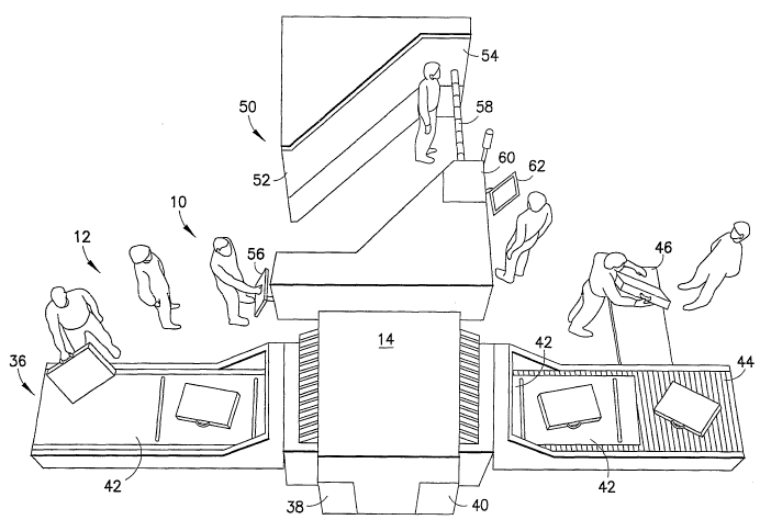
is identified generally by the numeral 10 in FIG. 1. The checkpoint 10
includes a luggage inspection portal 12 that has a detector 14. The detector
14 preferably includes at least one X-ray inspection device as used currently
at airports, and preferably at least two X-ray inspection devices for imaging
a
parcel from at least two different angles. The detector 14 further includes an
explosive detector, such as an ion trap mobility spectrometer (ITMS) as
shown in U.S. Patent No. 5,491,337 and in FIG. 2. Additionally, the detector
14 includes a vibrator for imparting a vibration to the luggage for purposes
of
separating particles of interest from the luggage. The detector 14 may
further include air jets for separating particles of interest from the
luggage.
The ITMS of FIG. 2 comprises a cylindrical detector 20 having
an inlet 22 at one end for receiving sample air of interest borne by a carrier
gas that has been doped with a low concentration vapor (typically a few parts
per million) employed as a charge transfer mediator. More particularly, the
inlet 22 communicates with a source of sample air of interest and a supply of
11
CA 02531587 2006-O1-05
WO 2005/008293 PCT/US2004/022197
carrier gas and dopant 16. Flows of gases to the inlet 22 are enabled by a
flow generator, such as a pump, illustrated schematically and identified by
the numeral 18 in FIG. 2. A heated membrane 19 is disposed near the inlet
22 and in communication with the source of the sample of air for blocking
passage of at least selected constituents of the air and for enabling passage
of other constituents of the air, including the constituents of interest. The
heated membrane preferably is formed from a microporeous refractory
material or from dimethyl silicone. The sample air, carrier gas, and dopant
molecules pass through the inlet 22 and are spread by a diffuser 24 into an
ionization chamber 26. The ionization chamber 26 is in the form of a shallow
cylinder with a diameter D, length L, and cylindrical wall 28 of a radioactive
material, e.g., nickel63 or tritium, which emits beta particles. Inlet 22
communicates with one end of the ionization chamber 26. A grid electrode E~
is provided at the end opposite the inlet 22, and is normally maintained at
the
same potential as the inlet end and the walls of the ionization chamber 26.
Thus a largely field-free space is provided in which electrons and ion charges
build up and interact with the sample molecules under bombardment by the
beta-particles from the radioactive walls. Beyond the ionization chamber 26,
the ionized sample gases pass through open electrode E~ and into an ion
drift region 30 having several field-defining electrodes E2-E". A collector
electrode or plate 32 is disposed at the end of the drift region 30 for
receiving
the ion samples reaching that end.
12
CA 02531587 2006-O1-05
WO 2005/008293 PCT/US2004/022197
Periodically a field is established across the ionization region
26, by creating a potential difference between the grid electrode E~ and the
inlet diffuser 24 and radioactive source 28, for about 0.1-0.2 mS, to sweep
the ions through the open grid E~ into the drift region 30 with the assistance
of the switching of the field between electrodes E~ and E2. The ions in the
drift region 30 experience a constant electric field, maintained by the
annular
electrodes E2-E", impelling them along the region and down toward the
collector electrode 32. The electrode 32 detects the arriving charge, and
produces signals that are amplified and analyzed through their spectra in the
spectrometer. The gases exit through an outlet in the wall next to the
electrode 32. After about 0.2 mS the field across the ionization region 26 is
again reduced to zero and the ion population is again allowed to build up in
the chamber 26 preparatory to the imposition of the next field. The polarity
of
the fields is chosen on the basis of whether the detector is operated in a
negative or positive ion mode. When detecting explosives, a negative ion
mode is usually appropriate, but when detecting narcotic samples positive
ion mode is preferred.
The baggage inspection portal 12 further includes a conveyor
36. The conveyor 36 is powered by a motor 38 that is illustrated
schematically in FIG. 1, and is operative intermittently to feed, stop and
then
feed again. The intermittent operation of the motor 38 is controlled by a
control unit 40 and can be overridden by manual control signals generated by
an operator. The conveyor 36 further includes separators 42 for separating
13
CA 02531587 2006-O1-05
WO 2005/008293 PCT/US2004/022197
the luggage of one passenger from luggage of another passenger. The
separators 42 can be incorporated integrally into the conveyor 36 at specified
distances from one another. Alternatively, the separators 42 can be placed
on the conveyor by the operator, thereby reflecting the fact that different
passengers will require different space on the conveyor 36 for their luggage.
Hence, the operator can place the separator 42 at appropriate locations
between the luggage of one passenger and the luggage of the next.
Alternatively, all items entering the baggage inspection portal are tagged
with
an RFID tag.
The detector 14 further includes a reader, such as an optical
reader for identifying the separators 42 and generating a signal in response
to the sensed presence of a separator 42 for stopping the conveyor 36 until
an override signal is generated. Alternatively, the reader is an RFID tag
reader. The outlet end of the conveyor is adjacent a cleared bag pick-up
station 44. The passenger may retrieve a cleared item of luggage at the
pick-up station 44. A search station 46 is adjacent the pick-up station, and
in
proximity to the outlet end of the conveyor 36. The search station 46 is used
for luggage that requires a hand check based on the results of prior
screening. either in the detector 14 or based on screening data of the
passenger.
The checkpoint 10 further includes a passenger screening
portal 50 with an inlet end 52 and an outlet end 54, as shown in FIGS. 1 and
3. The inlet end 52 includes an identification terminal 56 that requires each
14
CA 02531587 2006-O1-05
WO 2005/008293 PCT/US2004/022197
passenger to present some form of identification. The identification
presented at the terminal 56 can be a boarding pass, a credit card, or the
like. Alternatively, the identification terminal can read finger prints, hand
sizes or corneal patterns. The identification terminal 56 preferably includes
both visual and voice prompts to instruct each passenger of the actions
required and when to proceed further beyond the inlet end 52 of the
passenger screening portal 50. The visual and voice prompts produced by
the identification terminal 56 will instruct the passenger when to proceed
into
the passenger portal 50.
The passenger portal 50 illustrated in FIG. 1 includes a back
scatter X-ray device. The back scatter X-ray device may use commercially '
available technology to produce an X-ray screening for identifying the
presence of threat objects and indicating the location of such objects.
Additionally, the passenger portal 50 may include a detector for detecting the
presence of trace amounts of narcotics, explosives or other substances of
interest. The detector may be substantially in accordance with the provisions
of U.S. Patent No. 6,373,499, and hence may rely upon the thermal plume
generated by the body heat of each passenger. The plume rises upwardly
and entrains microscopic particles of substances of interest that may have
been handled by the passenger. For this purpose, at least a portion of the
passenger portal 30 may include a ceiling for receiving the thermal plume of
air generated by the patient, as shown schematically in FIG. 3.
CA 02531587 2006-O1-05
WO 2005/008293 PCT/US2004/022197
The outlet end 54 of the passenger portal 50 includes a traffic
arm or door 58 that will .control the egress of the passenger from the
passenger portal 50.
The checkpoint 10 further includes a control unit identified
generally by the numeral 60 in FIG. 1 and a monitor 62 that can be operated
by security personnel. The control unit 60 receives signals from the
identification terminal 56 and from a remote check-in location (not shown).
The check-in location will be operated by a ticketing agent trained to
identify
passenger travel or personal characteristics or traits that may be indicative
of
a need for further searching. For example, a ticket-in agent may identify a
particularly nervous or short-tempered passenger or a passenger that is
perspiring without apparent environmental cause. Additionally, the check-in
agent may notice certain travel characteristics, such as a cash purchase of a
ticket, a one-vvay ticket purchased shortly before flight or travel to or from
areas that have been identified as being a potential source of terrorists or
contraband. Additionally, the initial ticketing or check-in can compare the
name of the passenger with a database of names of passengers that require
further checking.
The control unit 60 communicates with the identification
terminal 56 and compares the identity of the passenger who is about to enter
the passenger portal 50 with input received from the check-in agent or from
the scan of known databases. The control unit 60 then generates a signal
which indicates the calculated threat level of the passenger. This threat
level
16
CA 02531587 2006-O1-05
WO 2005/008293 PCT/US2004/022197
may be used to adjust the intensity and duration of the tests carried out
automatically by the checkpoint. For known passengers, some of the tests
may be forgone completely. Also automatic alarm levels may be adjusted up
and down within the portal to ignore certain levels of threat. For example,
the
alarm level of the weapons detector may be set to ignore small metallic
objects such as coins on passengers with low threat levels. In this way, the
testing time may be reduced while still maintaining high security. Thus the
passenger and the corresponding baggage will be subject the same levels of
screening.
The calculated threat level can also be viewed by the operator
at the monitor 62. The results of the x ray scan and the passenger scan may
be displayed on the monitor, so that perceived high threat passengers may
be subject to increased scrutiny. Also, automatic detection devices may be
deployed to scan the x ray image and passenger weapons detection images
or outputs and will determine if any threat exists. Only doubtful images will
be presented for operator resolution on the monitor 62.
Some of the inspection processes may be automatically called
up by the control unit operating on the perceived threat from the particular
passenger or by setting global threat levels communicated from security
services. For example, the explosive check on luggage may not be carried
out at a time of low threat or for perceived low threat passengers. Such
automatic decisions will be transparent to the passenger.
17
CA 02531587 2006-O1-05
WO 2005/008293 PCT/US2004/022197
The control unit 60 further communicates with both the motor
38 for the conveyor 36 and with the traffic arm 58. The control unit 60 will
generate a signal for operating the traffic arm 58 only when the scan of the
luggage associated with a particular passenger has been completed. Thus,
the passenger and the luggage associated with the passenger will be
advanced simultaneously to the outlet ends of the luggage inspection portal
12 and the passenger inspection portal 50. In most situations, the passenger
wilt proceed directly from the outlet end 54 of the passenger portal 50 to the
luggage pick-up station 40. However, in certain instances signals received
by the controller 60 or determined by the operator as a result of the
checkpoint testing may indicate a need for further searching of the luggage
and/or the passenger. In these situations, a search officer will remove the
luggage from the luggage pick-up station 44 to the luggage search station 46
so that additional searching can be carried out. This procedure is illustrated
in the flow chart of FIG. 4. The corresponding passenger also will be
searched or scanned with a degree of scrutiny consistent with the searching
or scanning applied to the luggage.
18