Note: Descriptions are shown in the official language in which they were submitted.
CA 02531915 2005-12-29
CRD-5174
A
DISTAL PROTECTION DEVICE WITH
IMPROVED WALL APPOSITION
BACKGROUND OF THE INVENTION
1. Field of the Invention
The present invention relates to intravascular devices used to assist in
medical treatment and procedures. More specifically, the present invention
relates to a blood filtering system for preventing embolic material from
migrating
through a blood vessel during an intravascular procedure.
2. Discussion of the Related Art
Atherosclerosis is a complex disease, being primarily a result of buildup in
the arteries that may start as early as childhood and progress as one ages.
Progression may be rapid in some people. Blood vessels may become
completely occluded or more often narrowed and/or stenotic in a number of
ways. A stenosis may be formed by an atheroma which is typically a harder,
calcified substance which forms on the inside walls of the blood vessel. The
stenosis may also be formed by a buildup of thrombus material, which may
restrict blood flow through the vessel. In general, atherosderosis is the
result of
any combination of fat substances, cholesterol, waste products, calcium as
well
as other substances being deposited on the inside lining of the artery. This
buildup is often called plaque. Atherosclerosis can often lead to coronary
heart
disease, a major health concern today for both males and females in the United
States as well as abroad.
Atherosclerosis may also lead to strokes, and other disorders because of
the occurrence of blood clots, which may form in the narrowed arteries.
Although plaques can grow large enough to significantly reduce the blood flow
through an artery, most of the damage may occur when these plaques become
fragile and rupture. These are often referred to as vulnerable plaques. When
CA 02531915 2005-12-29
CRD-5174
vulnerable plaques rupture they typically cause blood clots to form that may
then
subsequently block blood flow or break off and travel through the blood vessel
to
another part of the body. If either situation happens, the result may be a
blocked
blood vessel that supports and nourishes the heart, which may cause a heart
attack. If a blood vessel that delivers blood to the brain is blocked, it may
cause
a stroke. If the blood supply to the legs is compromised, it may result in
limb
ischemia and in difficulty with walking and/or leg pain referred to as
daudication,
and may eventually cause gangrene.
The narrowing of an artery, also known as a stenotic lesion in the
vasculature, has motivated medical professionals to develop a number of
intravascular procedures which have evolved over time to treat this condition,
percutaneous balloon angioplasty being the most common. Percutaneous
balloon angioplasty is a procedure wherein a balloon catheter is inserted
within
the vasculature, and the balloon is expanded at the location of the lesion
essentially compressing the stenotic buildup against the inside of the vessel
wall.
More recently this procedure has been augmented by the deployment of a stent
or stents, at the location of the lesion subsequent to, or concurrently with
the
angioplasty. The stent acts as an internal scaffold within the vessel,
retaining an
open lumen and preventing further re-narrowing of the vessel. Generally,
stents
are primarily of two types, balloon expanding and self-expanding. As the terms
indicate, balloon-expanding stents are deployed/expanded in-vivo with the
assistance of a balloon, while self-expanding stents may utilize shape-memory
materials such as nitinol. The use of such alloys as nitinol (Nickel-Titanium
alloy), having shape memory characteristics, suitable biocompatibility, and
designed to be inserted into one's vasculature, is known in the art. These so-
called shape memory alloys have the ability to return to their original shape
when
exposed to the correct temperature conditions. The
shape memory
characteristics of these alloys, allow the devices to be deformed to
facilitate their
insertion into a body lumen or cavity. Upon being exposed to higher
temperatures within the body results in the device returning to its original
programmed shape. Thus one can employ the shape memory property to
expand the device to its original shape after being delivered through the
2
CA 02531915 2005-12-29
CRD-5174
vasculature in a reduced profile or compressed state. Nitinol can also have
super-elastic characteristics, which allow the device fabricated from such a
material as nitinol, to be deformed and restrained in the deformed condition
in
order to facilitate the insertion into a patient's vasculature. This
deformation
causes a phase transformation of the material. Once the device with super-
elastic characteristics is delivered, the restraint on the super-elastic
material can
be removed thus reducing the stress and allowing the previously compressed
super-elastic member to return to its original pre-programmed and un-deformed
shape, which results in a transformation back to the original phase.
While widespread intravascular procedures, particularly angioplasty
procedures have been extremely successful; the procedure itself may result in
development of an embolus. For example, during stent deployment and
positioning, abrasion of the vessel wall may dislodge material resulting in an
embolus. An embolus circulating within the blood vessels may lead to occlusion
of a vessel and/or formation of clots within the vasculature and/or body
organs.
Although the occurrence of this can be minimized with careful and proper
technique, when such an event does happen it may have serious consequences
to the patient. By adequately capturing and/or filtering the material
traveling in
the blood responsible for causing such an event one can avoid the serious
consequences that may result without such safeguards.
Multiple approaches to address capturing and/or filtering of the embolic
debris/material from blood have been attempted. These include baskets, nets,
suction, and even chemical modification of the debris (see U.S. Pat. No.
5,053,008, which utilizes and requires an additional conduit to transport
lysing
agents to the trapped embolus). Use of vascular filters in the Vena Cava for
capturing emboli has been disclosed (see U.S. Pat. Nos. 4,727,873 and
4,688,553). The designs of the Vena Cava filters continue to improve
addressing such issues as fit and preventing migration (see U.S. Pat. No.
6,443,972). Distal Protection devices using filtering baskets although similar
to
Vena Cava filters in function are typically temporarily positioned within the
lumen,
whereas Vena Cava filters are typically implanted within the vessel, most
often
the inferior Vena Cava, as the name implies. The use of a filtering basket
3
CA 02531915 2005-12-29
CRD-5174
positioned downstream from the procedure to capture the debris/material during
an intravascular procedure is one such method. Because these basket type
devices must be introduced into the vasculature and travel within the
vasculature
to be ultimately positioned to a location somewhat distal or downstream to the
region of interest, most, if not all, incorporate and utilize concepts and
features
that make the essential delivery through the vessel less traumatic (see U.S.
Pat.
No. 6,391,044). This can be accomplished by using a reduced size or
compressed version of the apparatus. This allows one to deploy the apparatus
to its normal working size when the apparatus is at the location of interest
within
the vessel.
The majority of these basket-type devices employ "expandable filters,"
meaning they may be fabricated from shape-memory materials which have the
property that when exposed to the relatively elevated temperature within the
body, they return to their initial programmed size. Alternately, on can rely
on the
superelastic property by removing the restraint on the geometry. These devices
are generally placed distal, or downstream of the stenosis in order to capture
any
fragments, debris, and/or embolic material, that may be dislodged or occur as
a
result of the presence and use of the device during an intravascular
procedure.
The downstream placement of the device takes advantage of the blood flow
within the vasculature, which will transport the undesirable material with it.
The
filtering membrane of the device is typically designed so as to allow blood
flow
through the membrane while limiting passage of the larger sized fragments and
debris such as micro and macro emboli. These fragments, debris, and/or
embolic material could potentially be carried beyond the device location with
the
blood flow downstream if not for such a filtering device as described herein.
While this method performs fairly well capturing a substantial portion of the
items
intended to be captured; many of these designs are optimized for circular
vessels. While outer vessel shapes are circular or slightly elliptical, the
internal
geometry of a vessel may often be non-circular as in an oval or elliptical
shape or
may even take the form of other non-circular geometries. Specifically, when
calcification is present within the vessel, the internal vessel geometry is
often
irregular. Furthermore, vessel cross-sectional shape may vary with the type
and
4
CA 02531915 2005-12-29
CRD-5174
location of vessel and vary across patients as well. Moreover, due to the
circulation of blood through the vessel and resulting forces, a dynamic
situation
exists, which may produce additional geometry changes to the normal vessel
shape. Thus expandable filters, which are generally designed for circular
vessels, may result in a lack of apposition against the vessel wall over at
least
some portion of the internal circumference of the vessel wall when one takes
into
account the additional factors described above. Such a gap or leak path may
occur when the resulting geometry of the expanded device is circular while the
inner luminal cross-sectional shape of the vessel is more often non-circular.
Such resulting gaps, between the device and inner luminal surface, may allow
the emboli that the device is designed to capture, adequate room to pass
through such a gap between the inner wall of the vessel and the outer confines
of the device. When this occurs, the primary purpose of the device, which in
this
case is to capture fragments, debris and/or embolic material, is defeated,
because the unfiltered flow path will allow for passage of the emboli. Even
when
the vessel itself is circular, conformance of a circular filter to the
internal lumen of
the vessel may not be optimal if In-folding" is present. "In-folding" is the
situation
when the unsupported membrane of the system folds in at positions located
between the strut locations where the membrane is supported by the struts.
This
situation can produce gaps between the inner vessel wall and the membrane
even in the idealized circular vessel at locations between adjacent struts. In-
folding may also occur when an oversized device (one that is sized larger then
the vessel it will be placed in) is utilized in order to ensure adequate
vessel
coverage. In this situation, when the struts of the oversized device make
contact
with the vessel wall, the device ceases to expand. As a result, this limited
expansion is short of its fully expanded programmed size and as such the
membrane is not fully taught. Thus the remaining slack present in the
membrane may lead to in-folding and thus allow for an unfiltered flow path.
Moreover, even in the absence of in-folding, utilization of a circular-type
device in
a truly circular vessel may not adequately conform to the internal lumen upon
vessel loading and/or deformation because the resulting device deformation may
not adequately match the deformation of the vessel. This dissimilar
deformation
5
CA 02531915 2005-12-29
CRD-5174
may thereby result in gaps or leak paths between the inner vessel wall and the
device upon loading and/or deformation of the vessel.
Accordingly, there is a need for a distal protection device with improved
filtering and vessel apposition that can allow for capturing of embolic debris
regardless of vessel size or shape or various loading regimes encountered by
the vessel.
6
CA 02531915 2005-12-29
CRD-5174
BRIEF SUMMARY OF THE INVENTION
The distal protection device with improved apposition in accordance with
the present invention overcomes the disadvantages and shortcomings of
currently available devices and satisfies the unmet needs of maximizing
capture
of embolic debris by improved vessel apposition in vessels of varying size and
shape in various loading and no-load regimes.
The present invention relates to an apparatus for intravascular filtering,
capable of capturing emboli in blood flowing within the vasculature and a
method
of using the device. The filtering device comprises an expandable basket and
is
configured to deploy radially outward which may be relative to a centrally
located
guide wire. Expansion of the filtering device with improved vessel conformance
is accomplished in a fashion resulting in improved filtering of blood in both
circular and non-circular vessels and for vessels both large and small as well
as
when the vessel itself encounters various internal and/or external loading
regimes.. Furthermore the incorporation or application of biological and/or
pharmaceutical agents can provide additional benefits when used in combination
with the present invention.
In accordance with one exemplary embodiment of the present invention,
the filtering basket and supporting struts work together to achieve the stated
objective of improved conformance and apposition to the internal vessel wall.
In
this exemplary embodiment of the present invention where the filtering basket
and struts work together, expansion of the filtering basket is decoupled from
the
struts, and as such, expansion of the filter basket can be independent of the
expansion of the supporting struts that are operatively connected to the
filtering
basket. Operatively connected in this instance in accordance with an exemplary
embodiments of the present invention equates to the struts connected to the
membrane such that radial strut movement controls the radial expansion of the
membrane but allows for independent longitudinal or axial movement of strut
relative to the membrane. For example, in accordance with the present
invention
one can operatively attach the strut to the membrane by allowing the strut to
7
CA 02531915 2005-12-29
CRD-5174
slide within loops fixed to the membrane thereby allowing the radial expansion
of
the membrane to occur independent of the axial translation of the individual
struts. In this exemplary embodiment, the independent expansion of each of the
supporting struts can independently act on the filtering basket enabling the
basket to expand as well. This expansion of the filtering basket may be non-
uniform. As a result, improved vessel wall apposition is achieved by the
independent radial expansion of each of the struts acting upon the filtering
portion of the device. This improved conformance to the inside surface of an
vessel wall results in improved filtering capacity by capturing emboli and/or
other
material which may otherwise be allowed to circumvent a device which does not
conform to the vessel wall as closely. This provides a significant patient
benefit.
In an additional exemplary embodiment of the present invention, a similar
result is achieved with a conformal filtering basket without supporting
struts. In
this alternate exemplary embodiment of the present invention, the filtering
basket
itself has the ability to expand, being constructed from either self-expanding
materials such as thin-film nitinol, self-expanding polymeric materials, or a
lattice
of self-expanding members that can act as a mesh, which upon expansion is
freely conformable. It is this free conformability that provides for improved
vessel
conformance. Stress relief and or removal of material from the filtering
basket
can be performed to further improve conformability of the filtering basket.
Expansion of the filtering basket of the present invention can also be
achieved by
alternate means such as mechanical or balloon expansion, which may or may
not, be used in conjunction with a self-expanding material.
In yet another exemplary embodiment of the present invention, the struts
themselves are constructed to be independent filtering elements that when
acting together with other filtering elements create a filter basket with
independent expansion relative to the adjacent strut/filter element.
Operatively
attached to each strut is one or more filtering flanges. The combined strut
and
filtering flange element interacts with adjacent strut and filtering flange
elements
creating a filtering cone with overlapping flanges to accommodate non-circular
geometries and which are capable of expanding to the appropriate internal
lumen or vessel diameter the device is positioned within.
8
CA 02531915 2005-12-29
CRD-5174
In a fourth exemplary embodiment of the present invention, improved
conformance in both circular and non-circular vessels is achieved and in-
folding
of the filtering aspect is addressed. In this exemplary embodiment of the
present
invention the path of a supporting strut is both axial and circumferential.
The
struts run axially in the distal portion of the filter and then each strut in
succession is directed circumferentially at the midpoint of the filter for a
limited
portion of the circumference of the membrane and then each strut returns to an
axial direction in the remaining proximal portion of the filter. This
exemplary
embodiment of the present invention allows for improved vessel conformance by
providing support to the filter membrane along a substantial portion of the
circumference of the device, located substantially within the middle third
between
proximal and distal ends of the device, which is in apposition with the lumen
of
the vessel wall. It is the circumferential portion of the strut acting upon
the
filtering membrane, which results in improved vessel conformance and which
eliminates the occurrence of in-folding by providing support to the filtering
membrane in apposition with the vessel wall over a significant portion of the
circumference.
In a fifth exemplary embodiment of the present invention, one can
improve conformance with the internal lumen of the vessel while further
reducing
the folded and/or compressed profile of the system by utilizing a series of
independent struts optimized for improved apposition in both circular and non-
circular vessels. This can be achieved by utilizing independent strut loops
that
occupy only the proximal portion of the filter thereby further reducing the
compressed profile of the distal portion of the filter due to the absence of
struts
from the distal portion of the filter basket. Each independent strut loop can
expand in a similar or dissimilar fashion relative to the additional strut
loops,
which allows for the improved conformance of the membrane to the vessel wall.
In accordance with the present invention, examples of strut loops can include
"U"
and "V" type loops. The looping of the strut is achieved by and best described
as
a substantially axial portion of the strut, which is then directed
circumferentially
for a portion of the circumference, the path of the strut then following a
second
substantially axial portion returning to the approximate starting position of
the
9
CA 02531915 2005-12-29
CRD-5174
strut and completing the loop. In "U" type loops, the circumferential portion
of the
loop in combination with the two axial portions can result in a shape similar
to the
letter "U", alternately in "V" type configurations, the distal axial portions
of the
strut may form a shape similar to the letter "V". The "V" type configuration,
which
facilitates easier and more efficient compression and/or folding of the
device, due
to the distal axial portions which can be aligned when compressed, results in
reduced profile dimensions which is extremely important given the delivery
considerations through the vasculature to the region of interest. The "V" type
configuration may also be cut from smaller profile tubing. It is important to
note
that any suitable configuration can be utilized. The circumferential portion
of the
strut, which is operatively attached to the membrane, allows the extent of in-
folding to be minimized while achieving improved vessel conformance, because
the circumferential portion of the strut ensures conformance with the vessel
wall
by providing support to the membrane which is adjacent to the vessel wall.
Since the struts in combination with the compressed or folded filtering
membrane
is the primary contributor to profile in the distal region of the device,
limiting the
strut loop to the proximal portion of the device minimizes the overall profile
of the
device due to the absence of struts in the distal portion.
The incorporation or application of biologically active or pharmaceutically
active compounds with the present invention is a further object of this
invention
and is an improvement to methods and/or devices which require the use of a
conduit to deliver the agent to the desired location. Compounds such as those
identified below may be applied as coatings on these devices and may be used
to deliver therapeutic and pharmaceutical agents which may include: anti-
proliferative/antimitotic agents including natural products such as vinca
alkaloids
(i.e. vinblastine, vincristine, and vinorelbine), paditaxel,
epidipodophyllotoxins
(i.e. etoposide, teniposide), antibiotics (dactinomycin (actinomycin D)
daunorubicin, doxorubicin and idarubicin), anthracyclines, mitoxantrone,
bleomycins, plicamycin (mithramycin) and mitomycin, enzymes (L-asparaginase
which systemically metabolizes L-asparagine and deprives cells which do not
have the capacity to synthesize their own asparagine); antiplatelet agents
such
as G(GP) 11b/111a inhibitors and vitronectin receptor antagonists; anti-
CA 02531915 2005-12-29
CRD-5174
proliferative/antimitotic alkylating agents such as
nitrogen mustards
(mechlorethamine, cyclophosphamide and analogs, melphalan, chlorambucil),
ethylenimines and methylmelamines (hexamethylmelamine and thiotepa), alkyl
sulfonates-busulfan, nirtosoureas (carmustine (BCNU) and analogs,
streptozocin), trazenes - dacarbazinine (DTIC); anti-proliferative/antimitotic
antimetabolites such as folic acid analogs (methotrexate), pyrimidine analogs
(fluorouracil, floxuridine, and cytarabine), purine analogs and related
inhibitors
(mercaptopurine, thioguanine, pentostatin and 2-chlorodeoxyadenosine
(cladribine)); platinum coordination complexes (cisplatin, carboplatin),
procarbazine, hydroxyurea, mitotane, aminoglutethimide; hormones (i.e.
estrogen); anti-coagulants (heparin, synthetic heparin salts and other
inhibitors of
thrombin); fibrinolytic agents (such as tissue plasminogen activator,
streptokinase and urokinase), aspirin, dipyridamole, tidopidine, clopidogrel,
abciximab; antimigratory; antisec.retory (breveldin); anti-inflammatory: such
as
adrenocortical steroids (cortisol, cortisone, fludrocortisone, prednisone,
prednisolone, 6a-methylprednisolone, triamcinolone, betamethasone, and
dexamethasone), non-steroidal agents (salicylic acid derivatives i.e. aspirin;
para-aminophenol derivatives i.e. acetaminophen; indole and indene acetic
acids
(indomethacin, sulindac, and etodalac), heteroaryl acetic acids (tolmetin,
diclofenac, and ketorolac), arylpropionic acids (ibuprofen and derivatives),
anthranilic acids (mefenamic acid, and medofenamic acid), enolic acids
(piroxicam, tenoxicam, phenylbutazone, and oxyphenthatrazone), nabumetone,
gold compounds (auranofin, aurothioglucose, gold sodium thiomalate);
immunosuppressives: (cyclosporine, tacrolimus (FK-506), sirolimus (rapamycin),
azathioprine, mycophenolate mofetil); angiogenic agents: vascular endothelial
growth factor (VEGF), fibroblast growth factor (FGF); angiotensin receptor
blockers; nitric oxide donors; antisense oligionudeotides and combinations
thereof; cell cycle inhibitors, mTOR inhibitors, and growth factor receptor
signal
transduction kinase inhibitors; retenoids; cyclin/CDK inhibitors; HMG co-
enzyme
reductase inhibitors (statins); and protease inhibitors.
The use of compounds in conjunction with the present invention can
provide distinct clinical advantages over existing therapies and/or devices.
More
11
CA 02531915 2005-12-29
CRD-5174
specifically, compounds that are capable of causing lysis or degradation of
the
embolic debris can be incorporated into the filtering portion of the present
invention. A factor to consider in the selection of such a compound is the
origin
of the debris be it thrombus, plaque, atheroma, or any other form representing
an
embolus. As the mesh and or pore size of the filtering aspect of the present
invention decreases, more embolic material may become trapped in the filtering
mechanism of the present invention, thereby increasing the load on the
filtering
portion. While small emboli (typically smaller than 100 microns) are not a
major
concern because of the body's natural ability to enzymatically degrade, digest
or
lyse the emboli, the embolic load on the filter itself can be overloaded and
result
in formation of a thrombus if the blood flow is significantly slowed to the
point
which allows for a thrombus formation. In this situation the incorporation or
application of compounds, which can degrade trapped emboli, can be beneficial.
Some exemplary suitable compounds may include: Tissue Plasminogen(TPA);
Streptokinase(SK); Reteplase; Tenecteplase; Urokinase; Lanoteplase;
Staphylokinase; and/or Nadroparin(anti-factor Xa). In addition, the filtering
portion of the present invention may incorporate an antithrombotic and/or
antithrombogenic agent to prevent the formation of a thrombus. Some
exemplary compounds may include: Heparin; Fragmin (dalteparin, low MW
Heparin); a monoclonal antibody such as ReoProTm (abciximab, antiplatelet
antibodies) Acenocoumarol; Anisindione; Dicumarol; Warfarin; Enoxaparin
(Lovenox); Anagrelide (Agrylin); lndomethacin (Indocin); Dipyridamole;
Clopidogrel; Aggrenox; and/or Coumadin. Furthermore, an affinity-binding
compound may also be incorporated with the filtering aspect of the present
invention by itself or in combination with other compounds. Affinity-binding
compounds can promote the binding and/or adhesion of embolic material thus
facilitating entrapment of embolic material and subsequent removal from the
blood stream. Whether incorporated into the strut or membrane by methods
such as chemical surface treatments, bombardment, placement into reservoirs,
or in the case of polymeric struts and membranes, blended with the material
itself, or by application of a coating to the struts and/or membranes with a
compound, any identified compound or combination of identified compounds
may be used. Furthermore any number of compounds may suggest themselves
12
CA 02531915 2005-12-29
CRD-5174
to one who is skilled in the art and may be utilized in connection with the
present
invention alone or in combination with other compounds.
The foregoing exemplary embodiments of the present invention each
provide a reliable, easy to manufacture, and simple to use device that
significantly improves wall apposition of the outer confines of the device to
the
internal surface of the vessel wall regardless of vessel size or shape or
loading
regime encountered. Furthermore, a relatively reduced profile of the delivered
device is achievable in accordance with the present invention. Moreover, any
combination of the items identified that are capable of expansion and provide
for
the ability to independently conform to both circular and non-circular
geometries
upon expansion may be utilized. As noted above, the incorporation of
biological
and/or pharmaceutically active agents with the present invention can be
utilized
for the additional purposes of preventing thrombus formation, promotion of
binding, and degradation of thrombus, all of which provide a patient benefit.
BRIEF DESCRIPTION OF THE DRAWINGS
Aspects of the present invention as well as the preceding information
may best be understood with reference to the subsequent detailed description
taken in conjunction with the accompanying exemplary drawings in which:
Figures la & lb are planar views showing the disparate cross-sectional
coverage area of an existing prior art filtering device in both a circular
vessel
and a non-circular vessel and the resulting gap in coverage due to non-
conformance of the device when positioned in non-circular vessels;
Figures 2a & 2b are planar views showing the disparate cross-sectional
coverage area by a filter with improved vessel conformance in accordance with
the present invention in both a circular and non-circular vessel. The
schematic
in figure 2b shows the minimization of gaps particularly in a non-circular
vessel
that results in contrast to the result achieved with prior art devices shown
schematically in figure lb;
13
CA 02531915 2005-12-29
CRD-5174
Figure 3 is a partial side view of the filtering device in accordance with
the present invention positioned on a guide wire;
Figure 4a is a partial side view of a conformal membrane-filtering basket
without supporting struts in accordance with the present invention;
Figure 4b is a partial side view of the conformal membrane basket with
stress relief to further improve vessel wall conformance in accordance with
the
present invention;
Figure 5 is a partial side view of the network of struts configured to
create a conformal lattice, which serves as the filtering aspect in accordance
with the present invention;
Figure 6a shows a partial side view of a filter basket with independent
filtering elements in accordance with the present invention;
Figure 6b is a detailed view of a single independent filtering element of
the filter basket as shown in figure 6a showing the strut and attached filter
flange in accordance with the present invention;
Figure 7a is a three-dimensional perspective view showing an additional
exemplary embodiment of a filtering device with improved vessel conformance
in accordance with the present invention;
Figure 7b is a partial side view showing schematically the circumferential
aspect of the struts as shown in figure 7a in accordance with the present
invention;
Figure 7c is a partial side view showing the strut configuration, with the
filter membrane removed for clarity, in accordance with the present invention;
Figure 7d is a partial side view of the embodiment shown in figure 7c
with the filtering membrane attached in accordance with the present invention;
14
CA 02531915 2005-12-29
CRD-5174
Figure 7e is a frontal view or head on view, as blood flow through the
lumen would encounter with the membrane removed for clarity, in accordance
with the present invention;
Figure 7f is a frontal view of the embodiment shown in figure 7e with the
filtering membrane attached in accordance with the present invention;
Figures 8a & 8b are planar sectional views of both a device without
support to the circumferential aspect resulting in the presence of in-folding,
and
of a device with the circumferential aspect of the filtering membrane
supported
by the strut resulting in improved vessel conformance in accordance with the
present invention and where in-folding is minimized and/or completely
eliminated because of the substantially circumferential 360 degree sealing of
the filter membrane against the vessel wall;
Figure 9 is a partial side view showing an additional exemplary
embodiment of a filtering device with improved vessel conformance and
reduced profile in accordance with the present invention;
Figure 10a is a three-dimensional perspective view incorporating four
strut loops of the "U" type configuration, operatively attached to a filtering
membrane in accordance with the present invention;
Figure 10b is a three-dimensional perspective view incorporating three
strut loops of the "U" type configuration operatively attached to a filtering
membrane in accordance with the present invention;
Figure lla is a partial side view of the four-loop embodiment of the "U"
type configuration shown in figure 10a in accordance with the present
invention;
Figure llb is a partial side view of the four-loop embodiment of the "U"
type configuration shown in figure 10a with additional filtering membrane
support in accordance with the present invention;
CA 02531915 2005-12-29
CRD-5174
Figure 11 c is a partial side view of the four-loop embodiment of the "U"
type configuration shown in figure 10a showing a scalloped membrane allowing
for additional reductions in profile in accordance with the present invention;
Figure 11 d is a partial side view of the four-loop embodiment of the "V"
type configuration shown in figure 10a showing a scalloped membrane allowing
for additional reductions in profile in accordance with the present invention;
and
Figure 11 e is a partial side view of the four-loop embodiment of the "U"
type configuration shown in figure 10a showing both additional filtering
membrane support and a scalloped membrane in accordance with the present
invention.
DETAILED DESCRIPTION OF THE PREFERRED EMBODIMENTS
Figures la & I b show a cross-sectional view for both a circular (100a) and
a non-circular (100b) blood vessel. Superimposed within these vessels in
figures
la & lb are schematics showing the approximated or relative cross-sectional
coverage area (101a) and (101b) for typical existing prior art devices in both
circular (100a) and non-circular (100b) idealized vessels. In this case the
vessel
wall (100a) & (100b) constrains the extent of the expansion of devices located
within the circumference of the vessel. With existing devices that uniformly
expand, this expansion is such that strut point locations represented by (1a)
&
(1 b) in the circular and non-circular vessels respectively, are uniformly
equidistant from the central axis (3a & 3b). As such, when strut point
locations
(lb) come into contact with the vessel wall (100b), at the moment one or more
struts make contact, all subsequent expansion is halted. As shown, given that
all
strut point locations (lb) expand in unison and uniformly, the right two and
left
two strut point locations (1 b) never make contact with the internal vessel
wall
surface (100b) because the top two and bottom two strut point locations (lb)
make prior contact with the vessel wall (100b) and thus the entire device is
prevented from further expansion. This results in a gap of coverage area (4)
that
may allow embolic material (5) to flow past the filtering device. The gap in
16
CA 02531915 2005-12-29
CRD-5174
coverage area is not only present in non-circular vessels, but depending on
the
extent of non-circularity of the vessel may result in further increasing the
gap
present and may also occur or increase due to various vessel loading
situations.
This is in contrast with the result achieved with an improved vessel
conformance device in accordance with the present invention. A similar set of
schematics represented in Figures 2a & 2b show the cross-sectional coverage
area and obtainable results in accordance with the present invention in both
circular (100a) and non-circular (100b) vessels. Figures 2a & 2b show cross-
sectional views for both a circular (100a) and a non-circular (100b) blood
vessel.
Superimposed within this vessel is a schematic showing the cross-sectional
coverage area (102a) and (102b) for an improved vessel conformance devices in
accordance with the present invention in both circular (100a) and non-circular
(100b) vessels. In this case the vessel wall (100a) & (100b) constrains the
extent of the expansion of devices located within the circumference of the
vessel
as before. However because the strut point locations (2a & 2b) are decoupled
from the filtering portion these strut points can continue to expand
independently
of each other and the filtering basket, even when one strut point location
makes
contact with the vessel wall. Thus the outward expansion of the other strut
points (2b) are not inhibited and thus can continue to expand until each
independently makes contact with the vessel wall regardless of the nature of
the
cross-sectional shape of the vessel. This results in minimization and/or
avoidance of any gap in coverage area.
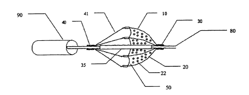
Figure 3 shows a side view of an exemplary embodiment of the present
invention, positioned on a guide wire (80). The filter basket (10) includes
one or
more struts (20), which serve to provide support and impart shape to the
filter
membrane (50). The filter membrane (50) in this exemplary embodiment is
shown with uniform holes (22), but can also have a distribution of varying
diameter holes to improve filtering performance or optimize filtering
performance
to achieve the desired result. Any number of designs may suggest themselves
to one who is a skilled artisan in the field and may be utilized in connection
with
the present invention. The distal ends of the struts (20) are pivotally
attached to
supporting collar (30), which may be permanently, removably, or operatively
17
CA 02531915 2005-12-29
CRD-5174
attached to guide wire (80). When operatively attached, supporting collar (30)
can slide and/or rotate with respect to guide wire (80). The struts (20) are
operatively attached to the filter membrane (50) which taken together form the
filter basket (10). The distal ends of additional tension members (41), attach
to
proximal ends of struts (20), while the proximal ends of these tension members
(41) are fixed to the closure ring (40). When proximal movement (ie: away from
supporting collar (30)) is imparted to closure ring (40) this increases the
tension
in tension members (41) such that strut members (20) are pulled radially
inward
toward guide wire (80) allowing for filter basket (10) comprised of filter
membrane
(50) and struts (20) to be collapsed with any retained debris to be captured
in
basket. The entire assembly can then be pulled back into retaining sheath
(90).
An inner sleeve (35) whose axial position relative to guide wire (80) can
impart
motion to either closure ring (40) or supporting collar (30) in order to draw
the
assembly into the retaining sheath (90) or to deliver the assembly from the
retaining sheath (90) may also be present. The pore size of filter membrane
(50)
can be optimized by altering the diameters of the individual pores (22) as
well as
their location of different sized pores relative to each other in order to
maximize
optimal blood flow through the membrane (50) while still filtering debris for
whose
size is of consequence. Preferred pore size diameters of individual pores (22)
of
the present invention range from approximately 50 to 150 microns, however any
number of suitable combinations of large and small size pores is also possible
as
is the distribution of said pores with respect to the filter membrane (50).
Figure 4a shows a partial side view of an additional exemplary
embodiment of the present invention. Here, the filter basket (50) is a
flexible
expanding conical membrane. This membrane can be constructed from various
materials such polyurethane and/or nitinol. Nitinol thin film is particularly
advantageous because of its appropriate mechanical properties coupled with its
reduced profile. The skilled artisan will recognize that any number of
suitable
biocompatible materials may be employed for this purpose. The distal end of
the
filter membrane is operatively attached to the proximal face of the supporting
collar (30). The membrane can be constructed with geometric relief (21), as
shown in Figure 4b to provide adequate flexibility, minimal thickness and/or
18
CA 02531915 2005-12-29
CRD-5174
= .
combinations of any of the afore mentioned items in order to maximize
conformability to non-circular lumen cross-sections (100b).
Figure 5 shows a partial side view of the filter basket configured from
longitudinal (24) and circumferential (23) struts alone without the presence
of a
membrane to allow for adequate expansion in order to conform to non-circular
vessels (100b). In this embodiment the struts (23 & 24) are combined to form a
lattice, which can then serve as both the structural support as well as the
filtering
aspect without the use of a filtering membrane. The circumferential aspect may
be a single helically wrapped strut that runs substantially perpendicular to
the
multiple longitudinal struts (24) or a combination of multiple struts
substantially
circular in geometry that are free to expand radially and substantially
parallel to
each other and substantially perpendicular to the longitudinal struts (24).
Figures 6a & 6b show an alternate exemplary embodiment of the present
invention in which multiple independent filter flanges (21) are connected to
independent struts (20), which are operatively attached to the proximal face
of
the supporting collar (30) or in an alternate fashion to the external
circumference
of the supporting collar (30) or in an additional alternate fashion to the
inner
aspect of the supporting collar (30) in order to combine to form a nested
filter
basket (51) and are utilized to improve conformance with the internal vessel
the
device is located within. The detail view of figure 6b shows an isometric view
of
a single member of an additional exemplary embodiment of the invention
utilizing
filter flanges (21) as shown in figure 6a. In this exemplary embodiment the
filtering flange (21) is attached to the independent strut (20) whose distal
end is
attached to supporting collar (30). Through holes (22) are shown on filter
flange
(21) to allow for blood to pass through while maintaining adequate filtering
capacity to capture the debris. The through holes (22) can vary in size but
are
preferably between 50 and 150 microns. In addition the distribution and number
of through holes (22) can be varied as well. Several of these strut
combination-
filtering flanges would operate in concert with each to create a filtering
basket
(51) as shown in figure 6a. Conformity to non-circular vessels (100b) is once
again achieved by independent expansion of each strut/filtering flange
combination.
19
CA 02531915 2005-12-29
CRD-5174
Figures 7a & 7b show an isometric view of an additional exemplary
embodiment of the present invention, which is characterized by each of the
individual strut paths (20) that run or are aligned both axially and
circumferentially. In this exemplary embodiment of the present invention, the
distal end of the individual strut (20) is attached to the supporting collar
(30) and
is substantially aligned with the guide wire (80) (not shown in figure 7a &
7b) in a
substantially axial direction. Approximately mid-way or in the middle third of
the
device but distal to the proximal opening of the filter basket (50) the strut
(20) is
directed circumferentially for a portion of the circumference of the filter
basket
only to be aligned with the guide wire (80) (not shown in this figure) once
more as
the proximal end of the strut (20) is again directed axially which then
terminates
at the supporting collar (40). This configuration of the strut (20), in
particular the
circumferential portion of the strut (20), allows for improved apposition of
the filter
basket (50) to the internal circumference of the lumen vessel wall (100) as
shown in Figures 8a & 8b. Figure 8(a) shows a typical cross-section of the
vessel wall with a filter membrane (50) supported solely by the axial portion
of
eight struts (20). The presence of in-folding between adjacent struts is
apparent
resulting in a gap (44) between the filter basket (50) and vessel wall (100)
that
can allow for passage of emboli. Figure 8(b) shows a similar cross-section of
the
vessel wall (100) with a filter membrane (50) supported by the struts (20)
that for
a portion of the circumference are directed circumferentially. As figure 8(b)
shows, the gap due to in-folding is eliminated due to the additional support
provided by the circumferential portion of the strut (20) to the filter
membrane
(50) against the vessel wall (100). By increasing the length of the
circumferential
portion of the struts (20) one can effectively reduce the number of struts
(20)
required to provide support to the filter membrane (50) without any decrease
in
apposition of the filter basket/membrane to that of the interior of the vessel
wall
(100). This decrease in the number of struts (20) can result in additional
reductions in profile of the overall device thus allowing for delivery to
smaller
vessels. Figures 7c & 7d show a side view of this exemplary embodiment of the
present invention both with and without the filter membrane (50). Figures 7e &
7f
show frontal views both with and without the filter membrane (50) in which one
CA 02531915 2005-12-29
CRD-5174
exemplary configuration of filtering holes (22) of the present invention can
be
seen as shown in figure 7f.
Figure 9 shows an alternate exemplary embodiment of the present
invention for whose compressed profile is further reduced by the omission of
struts (20) from the distal portion of the filter basket (50). As shown in
figure 9 as
well as in figures 10a & 10b, the struts (20) begin from a position proximal
from
the filter basket and are directed substantially axially until they reach the
proximal
opening of the filter basket (50) at which point they are directed
circumferentially
for a portion of the circumference of the filter basket (50) and then
redirected
back in the axial direction to the proximal starting position thus forming the
substantial portion of a loop. This is repeated for each strut present, which
allows for improved conformance of the filter basket's proximal opening to
that of
the vessel wall (100) in a similar fashion as was accomplished in the previous
embodiment without adding additional profile to that of the filter basket (50)
in the
distal region due to the absence of struts (20) in the distal region. In this
exemplary embodiment of the present invention, the distal supporting collar
(30)
is optional as the strut loops serve both to provide shape and support to the
filter
basket (50). As an example, the filter basket may be substantially spherical
in
shape or parabolic. Thus the filter basket can be formed into a net or
parachute
shape without the need for the distal supporting collar (30), or alternately a
supporting collar (30) can be attached if additional control of the filter
basket (50)
is desired.
Figures 10a and 10b represent examples of two specific embodiments in
accordance with the present invention with said supporting collar (30)
present.
Figure 10a is a four-loop configuration comprised of four independent strut
loops
(20). While figure 10b represents a three-loop configuration comprised of
three
strut loops (20). For each strut loop (20) the terminal starting and ending
points
of the loop (20) are fixed to the proximal support ring (40) while the distal
circumferential portion of each respective loop is fixed to the proximal
opening of
the filter basket (50). In this exemplary embodiment, the distal support
collar (30)
is optional in the configurations shown. Furthermore, although not shown,
filter
membrane (50) can be optimized for filtering capacity by incorporating a
21
CA 02531915 2012-11-06
CRD-5174
combination of pores with consistent or varying sizes and distributions. In
each
exemplary embodiment, the device including both loops (20) and proximal
support ring (40) may be cut from a single tube eliminating the need for
separate
structural components. As an example, laser cutting techniques for stent
manufacturing can be employed to fabricate the embodiments described in
accordance with the present invention. Cutting all or most of the structural
components from a single tube by laser cutting or other appropriate methods
provides significant cost savings as a result of the reduced number of
manufacturing process steps. In certain instances, formed wire may also be
used to fabricate the device in accordance with the present invention. Some
device designs and shapes simply do not lend themselves to cost effective
laser
cutting and thus wire forming would be more cost effective. Supporting struts
(20) can be fabricated from a number of biocompatible materials including
metals, ceramics, and polymers. Preferable materials for the supporting struts
(20) are shape memory metals and super-elastic alloys such as nitinol.
Additional embodiments are shown in figures 11 a through lie in which
the three or four loop configuration can be augmented by providing additional
filter support accomplished by strut member (26) as shown in figures 11 b
&lie.
These embodiments of the present invention are also capable of being
fabricated from a single tube. Preferably these additional intermediate strut
members (26) would be located between the struts having the loop configuration
(27). Alternately, the strut loop configuration (27) can be a "U" type
configuration
as shown in figure 11c or a "V" type configuration as shown in figure 11d.
Alternately, the membrane (50) can be scalloped (51) as shown in figures 11c,
lld & lie, which can result in additional profile reductions without any
decrease
in filtering effectiveness.
Although what has been shown and described is what is believed to be
the most practical and preferred embodiment of the present invention, other
forms of, and departures from the specific designs described and shown, will
suggest themselves to those skilled in the art and may be used without
departing
from the scope or essential characteristics of the present invention.
The
present invention is not restricted or limited to the foregoing described
22
CA 02531915 2005-12-29
CRD-5174
embodiments, but rather should be constructed to cohere with all variations,
combinations, and modifications that may fall within the scope of the appended
claims.
23