Note: Descriptions are shown in the official language in which they were submitted.
CA 02531931 2005-12-29
FAST CHANGE TRANSFORMER CONNECTOR AND ADAPTOR
FIELD OF THE INVENTION
The present invention relates to the field of electric power distribution,
and,
more specifically, to fast change transformer connectors, which enable
changing a
transformer without disconnecting electric cables from the connectors.
BACKGROUND OF THE INVENTION
Transformers are key components presently in electric power distribution
networks. Generally, electric power is distributed from electrical substations
at high
voltage typically in excess of 6,000 volts to minimize losses. Transformers
are
required to reduce the voltage down to lower levels, such as 120 volts, for
local
distribution to commercial and residential customers.
A transformer commonly used for this purpose is housed in a steel cabinet
on a concrete platform or pad at ground level. The transformer itself includes
primary and secondary coils housed in an oil-filled transformer well, the oil
being
provided to keep the coils cool. Typically, studs, to which cables, or in a
general
term, conductors, carrying high voltage power to the primary coils, and to
which
cables carrying reduced voltage from the secondary coils can be attached,
protrude
laterally outward from the transformer through the wall of the transformer
well.
1
CA 02531931 2005-12-29
The studs are insulated from the wall of the transformer well by an insulating
bushing or seal, which must be impermeable to the oil filling the transformer
well.
There are usually two to six studs for attaching incoming cables to the
primary side,
and three to four studs for attaching outgoing cables to the secondary side.
Typically, there are a minimum of three studs required on the secondary side,
one
for each of two phases and one for a return or ground cable.
Transformers of this type may be used to deliver electric power to a
relatively
small number of end consumers. To supply each such consumer, one cable from
each of the studs on the secondary side of the transformer is required.
Typically,
then, a number of cables are connected to each of the studs, one for each of
the
consumers being served.
Transformer connectors are used to attach the individual cables to the studs.
One of the most commonly used transformer connectors is spade connector. A
spade connector has a female connection end which is screwed onto a
transformer
stud through the screw threads on both of the stud and the spade connector.
Each cable end encapsulated in a cable end lug is screwed onto the spade
connector by a set of screw through one of the cable adapting ports of the
spade
connector.
With these traditional spade connectors, when a transformer needs to be
2
CA 02531931 2005-12-29
replaced because it is no longer functioning, an electrician has to disconnect
each
of the cables, usually from three to thirty cables, before the spade connector
can be
taken off from the stud by rotating the spade connector around the stud.
Moreover,
each disconnected cable has to be grounded immediately for safety reasons.
After
the old transformer is replaced by a new transformer and the spade connectors
are
connected onto the studs of the new transformer, each one of the disconnected
cables then has to be bolted onto the spade connector again.
Furthermore, the cable end lug closest to the stud on the spade connector
are relatively difficult to access. To reach a set of bolt and nut for a cable
end lug
axially closest to the stud along the cable, the electrician must reach in
toward the
stud over a number of cables. Even worse, the inner set bolts may not be
readily
visible, forcing the electrician to work blindly. Moreover, as the three or
four studs
are often arranged one above the other on the wall of the transformer well,
the
electrician may often be required to reach between two layers of cables to
adjust
the blot of a cable attached close to a stud. Still further, bolts might have
become
corroded causing extreme difficulty in removing the cables.
It is apparent that this is a lengthy and labour intensive process. It usually
takes from about two and half hours to about three hours to change a
transformer
that carries thirty electrical cables, mainly because the time required for
disconnecting and connecting the cables to the spades.
Attempts have been made to address these problems. One such attempt is
3
CA 02531931 2005-12-29
multi-tap stud connectors. A multi-tap stud connector has a block structure
with a
transformer stud port and a plurality of cable ports. A multi-tap stud
connector is
connected to a transformer stud through the transformer stud port and fastened
by
screws along the side of the transformer stud port. To disconnect the multi-
tap stud
connector, one loosens the screws, typically two, and detaches the multi-tap
stud
connector from the transformer stud without disconnecting electrical cables.
The
multi-tap stud connectors are currently used as an after market product, to
replace
spade connectors during replacement of a non-functioning transformer. Multi-
tap
stud connectors have certain disadvantages. As described above, a multi-tap
stud
connector is connected to a transformer stud through the transformer stud port
and
fastened by two screws along the side of the transformer stud port. Such a
connection is not as secure as the connection of a traditional spade
connector,
which is directly bolted on to the transformer stud. Furthermore, multi-tap
connectors are made of aluminum, which is different from the transformer stud
material of brass. For a long term use, the connection between aluminum and
brass tends to become loose, causing poor connection between the transformer
and the connector. For most transformers, particularly the large transformers,
spade connectors are still the most commonly used in the field.
Therefore, it is apparent that there exists a continuing need to provide
improved transformer connectors that enable the rapid change of a transformer
and
reduce power supply downtime. The present invention represents a novel
approach
toward a solution of the problems associated with the lengthy and labor
intensive
4
CA 02531931 2005-12-29
process involved in changing transformers.
CA 02531931 2005-12-29
SUMMARY OF THE INVENTION
In one embodiment, the present invention provides transformer connectors
which enable fast replacement of an electric transformer without disconnecting
electrical cables. The transformer connector comprises a cable connector
having a
cable attachment body with a plurality of cable attachment ports, a connector
extension connected, to the cable attachment body, and a stud slide adaptor
connected to a side of the connector extension; and a stud screw adaptor
complimentary to a transformer stud, for connecting the transformer stud and
the
stud slide adaptor of the cable connector.
In a further embodiment, the present invention provides a transformer
adaptor, which can be used to connect an electrical cable connector to a
transformer stud. The transformer adaptor comprises an inter-connector
comprising
a connecting shaft having screw threads at one end; and a stud slide adaptor
connected to a side of the connecting shaft at the opposing end; and a stud
screw
adaptor complimentary to a transformer stud, for connecting the transformer
stud
and the stud slide adaptor of the inter-connector. The transformer adaptor of
the
present invention can be used with existing transformer connectors, such as
spade
connectors, for conveniently detach the transformer connectors without
disconnecting the electrical cables.
In another embodiment, the present invention provides transformer
6
CA 02531931 2005-12-29
connectors which enable fast replacement of an electric transformer without
disconnecting electrical cables. The transformer connector comprises a cable
connector having a cable attachment body with a plurality of cable attachment
ports,
a connector extension with the first end connected to the cable attachment
body,
and a stud slide adaptor connected to a side of the connector extension near
the
second end; and a stud screw adaptor having a threaded opening complimentary
to
a transformer stud, for connecting the transformer stud and the stud slide
adaptor of
the cable connector.
Moreover, the transformer connector can further comprise an adaptor
extension. The adaptor extension has an extension body having a first end
portion
and an opposing second end portion, a front side and a rear side. The
extension
body has an unthreaded opening at the first end portion for adapting to the
transformer stud and engaging with the stud screw adaptor from the rear side;
and
an extension connection means at the second end portion for connecting the
stud
slide adaptor of the cable connector from the front side of the extension
body.
In a further embodiment, the transformer connector of the present invention
has a cable attachment section which comprises cable receiving body having a
plurality of receiving slots, each thereof for receiving a cable; and a
plurality of
removable sliding cable fastening blocks disposed within the plurality of
receiving
slots. Each of the sliding cable fastening blocks can be slid in and out from
the
receiving slot for receiving and fastening a cable.
7
CA 02531931 2005-12-29
In yet a further embodiment, the present invention provides a transformer
adaptor, which can be used to connect an electrical cable connector to a
transformer stud. The transformer adaptor comprises an inter-connector
comprising
a connecting shaft having screw threads at one end; and a stud slide adaptor
connected to a side of the connecting shaft at the opposing end; and a stud
screw
adaptor having a threaded opening complimentary to a transformer stud, for
connecting the transformer stud and the stud slide adaptor of the inter-
connector.
The transformer adaptor of the present invention can be used with existing
transformer connectors, such as spade connectors, for conveniently detach the
transformer connectors without disconnecting the electrical cables.
Furthermore,
the transformer adaptor can also comprise an adaptor extension, as described
above, for connecting the inter-connector to the transformer.
8
CA 02531931 2005-12-29
BRIEF DESCRIPTION OF THE DRAWINGS
The above and other features and advantages of the present invention will
be more clearly understood from the following detailed description taken in
conjunction with the accompanying drawings, in which:
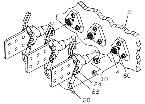
Fig. 1 is a perspective view of three transformer connectors of the present
invention, showing the stud slide adaptor of the transformer connectors to be
attached to each of three studs of the transformer with electrical cables
attached to
each of the transformer connectors.
Fig. 2 is a side view of a transformer connector of one embodiment of the
present invention.
Fig. 3A and 3B are perspective views of the transformer connector shown in
Fig. 2, showing the stud slide adaptor of the transformer connector to be
attached to
a stud of a transformer.
Fig. 4A and 4B are side views of the transformer connectors of one
embodiment of the present invention, showing two different geometry shapes at
contact surfaces of the stud slide adaptor and stud screw adaptor.
Fig. 5A and 5B are perspective views of the contact surfaces of the stud slide
9
CA 02531931 2005-12-29
adaptor and stud screw adaptor of transformer connectors shown in Fig. 4A and
4B,
respectively.
Fig. 6 is a perspective view of the transformer connector having a multi-tap
block as the cable attachment body of one embodiment of the present invention.
Fig. 7 is a perspective view of the transformer adaptor of one embodiment of
the present invention.
Fig. 8 is a perspective view of the transformer adaptor of one embodiment of
the present invention, which is to be connected to a traditional spade
connector and
a transformer stud.
Fig. 9 is a side view of the transformer adaptor shown in Fig. 8.
Fig. 10 is a perspective view of a transformer adaptor of a further
embodiment of the present invention, wherein the adaptor extension has a
threaded
shaft for connecting the inter-connector.
Fig. 11 is a perspective view of a transformer adaptor of a further
embodiment of the present invention, wherein the adaptor extension has a
threaded
opening for connecting the inter-connector by bolt and nuts.
CA 02531931 2005-12-29
Fig. 12 is a side view of the transformer adaptor of Fig. 10.
Fig. 13 is a perspective, and partially exploded view of a transformer
connector of a yet further embodiment of the present invention, wherein the
cable
attachment section has a plurality of receiving slots and each has a removable
sliding cable fastening block.
Fig. 14 is a top partial view of the transformer connector of Fig. 13 with one
sliding cable fastening block removed from one receiving slot.
Fig. 15 is a partially exploded perspective view of a sliding cable fastening
block.
Fig. 16 is an enlarged perspective view of a receiving slot showing the
retainer ridge.
Fig. 17 is a perspective view of a variation of the transformer connector of
Fig. 13, wherein the cable attachment section has two rows of receiving slots.
11
CA 02531931 2005-12-29
DETAILED DESCRIPTION OF THE INVENTION
Referring now to the drawings. As shown in Fig. 1, three transformer
connectors 10 of the present invention are to be attached to a transformer 2.
A
plurality of electrical cables 20 are attached to transformer connector 10,
wherein
each cable 20 is connected to transformer connector 10 through a cable end lug
22,
and secured onto transformer connector 10 by a set of bolt and nut 24. Each
cable
20 provides electricity from transformer 2 to a user.
As shown in Figs. 2, 3A and 3B, transformer connector 10 comprises an
electrical cable connector 30, and a stud screw adaptor 60 having a threaded
opening 62 which has internal threads complimentary to a transformer stud 4,
for
connecting transformer stud 4 and cable connector 30. The cable connector 30
includes a cable attachment body 32 having a plurality of cable attachment
ports 34;
a connector extension 40 having a first end 41 connected to cable attachment
body
32; and a stud slide adaptor 50 connected to a side of connector extension 40
near
second end 42. Stud slide adaptor 50 has an opening 52, wherein center axis 56
of
opening 52 is substantially parallel to the longitudinal axis of connector
extension
40. The transformer connector 10 further includes a bolt nut 66 for fastening
stud
slide adaptor 50 onto transformer stud 4.
As shown in Fig. 3A and 3B, stud slide adaptor 50 has an unthreaded
circular opening 52 for adapting to transformer stud 4. The diameter of
circular
12
CA 02531931 2005-12-29
opening 52 is greater than the diameter of transformer stud 4, so that stud
slide
adaptor 50 can be conveniently adapted onto transformer stud 4. The stud slide
adaptor 50 has a contact surface 54, which is in perpendicular to central axis
56 of
circular opening 52. The contact surface 54 interfaces with a contact surface
64 of
stud screw adaptor 60. As shown, contact surfaces 54 and 64 can have a
complimentary geometry shape for providing maximum surface contact between the
two surfaces. Fig. 3A and 3B show a rectangular teeth shape at contact
surfaces
54 and 64. However, various shapes can be utilized, such as sine wave shape
and
triangular shape shown in Fig. 4A, 4B, 5A and 5B, and a flat surface.
Preferably,
contact surfaces 54 and 64 have a large contact area, and a smooth contact in
order to conduct electricity effectively, and to avoid poor connections.
Furthermore, a proper complimentary geometry shape, such as rectangular
teeth shape, sine wave shape and triangular shape also provide an inter-
locking
mechanism between stud slide adaptor 50 and stud screw adaptor 60. The inter-
locking interface facilities an electrician's assembling process, and ensures
proper
contact between stud slide adaptor 50 and stud screw adaptor 60.
The external shape and size of stud slide adaptor 50 and stud screw adaptor
60 can be the same, as shown in the Fig. 2, 3A and 3B. However, they can also
be
different. For example, stud screw adaptor 60 can be a larger block with a
circular
central indentation complimentary to the external shape and size of stud slide
adaptor 50. In this type of structure, stud slide adaptor 50 can be inserted
into the
13
CA 02531931 2005-12-29
indentation to ensure a proper connection. The bolt nut 66 is a regular
commercially available bolt nut as long as it is compatible with transformer
stud 4.
Preferably, cable connector 30 has an integrated structure having cable
attachment body 32, connector extension 40, and stud slide adaptor 50 moulded
together. An integrated structure provides structural strength, and reduces
connection interfaces, which is desired for conducting electricity
effectively. The
cable connector 30 can be made of copper, iron, aluminum, and other suitable
electrical conducting materials.
As shown in Fig. 2, 3A and 3B, cable attachment body 32 has a structure of
traditional spade connector. However, other suitable structures, such as a
structure
of multiple tap stud connector, can also be used, as illustrated in Fig. 6. As
shown
in Fig. 6, cable attachment body 32 merely connects electrical cables 20
through
cable attachment ports 34, which are secured by a pair of screws 38. It is
understood that the connection with transformer is provided by stud slide
adaptor 50
and stud screw adaptor 60, regardless of the shape and mechanism of cable
attachment body 32. Several existing transformer connectors can be modified by
incorporating connector extension 40 and stud slide adaptor 50 of the present
invention. Their individual cable connection mechanism can be maintained.
The connector extension 40 as shown is a straight circular shaft with an
enforcement rim. However, other suitable shapes and structures, such as a
square
14
CA 02531931 2005-12-29
shape at the cross section of the shaft, and with a certain angle along the
shaft, can
also be utilized for the purpose of the present invention. The length and
diameter of
the shaft can be determined depending on the structure of cable attachment
body
32, the number of cables, and the weight that the transformer connector 30
carries.
The transformer connector of the present invention provides a convenient
connection mechanism between the transformer and the electrical cables. To
connect transformer connector 10 to transformer 2, an electrician first screws
stud
screw adaptor 60 onto transformer stud 4, then slides stud slide adaptor 50
onto
transformer stud 4 and engages stud screw adaptor 60, and last screws on bolt
nut
66 to tighten the connection between stud slide adaptor 50 and stud screw
adaptor
60. To disconnect transformer connector 10 from transformer 2, the electrician
simply reverses the process described above. Since no rotation is required to
unscrew cable connector 30 around transformer stud 4, once electrical cables
20
are connected to cable connector 30, they do not need to be disconnected in
the
process of changing transformer. Moreover, when cable connector 30 is
disconnected from transformer stud 4 during the change of transformer, only
one
time grounding of cable connector 30, instead of grounding of disconnected
each
cable, is required. This convenient connection mechanism, provided by the
engagement of stud slide adaptor 50 and stud screw adaptor 60 with transformer
stud 4, offers substantial reduction of time and labour involved in replacing
a
transformer. The estimated time for changing a transformer connected with
thirty
cables can be reduced from an original two and half to three hours down to
thirty
CA 02531931 2005-12-29
minutes to about one hour. With such a substantial reduction on the electrical
power supply downtime, the impacts on financial recovery of consumers,
particularly manufacturers, cost reduction of power suppliers, and consumer
living
conditions are enormous. Therefore, the transformer connector of the present
invention has important economical, financial and social significance.
In the second embodiment, the present invention is related to a transformer
adaptor. As shown in Fig. 6, transformer adaptor 70 comprises an inter-
connector
80, and a stud screw adaptor 60 for connecting inter-connector 80 and
transformer
stud 4. The inter-connector 80 includes a connecting shaft 82 which has
embedded
male screw threads at one end 84, also called cable end; and a stud slide
adaptor
50 connected to a side of said connecting shaft at the opposing end 86, also
called
transformer end. The transformer adaptor 70 further includes a bolt nut 66
which is
described previously.
The structures of stud slide adaptor 50 and stud screw adaptor 60 of
transformer adaptor 70, and the mechanism of connection to transformer 2 are
the
same as those of transformer connector 10 described in detail in the first
embodiment.
As illustrated in Fig. 8 and 9, transformer adaptor 70 is used to connect a
cable connector which has embedded female screw threads within the body of the
cable connector, which is commonly used for connecting to transformer stud 4.
16
CA 02531931 2005-12-29
Fig. 8 shows the female adapting end 92 of a traditional spade connector 90.
Traditionally, to connect spade connector 90 onto transformer 2, an
electrician turns
spade connector 90 around transformer stud 4, and then attach cables 20 to
spade
connector 90. To disconnect spade connector 90 from transformer 2, the
electrician
has to disconnect each individual cable 20 before spade connector 90 can be
turned around transformer stud 4 in the opposite direction.
With transformer adaptor 70 of the present invention, one can continue to
use existing spade or other connectors without disconnecting electrical cables
from
these connectors. As shown in Fig. 8 and 9, to connect a conventional spade
connector 90 to transformer 2, the electrician first adapts inter-connector 80
to
spade connector 90 by screwing cable end 84 of inter-connector 80 into female
adapting end 92 of spade connector 90, and screws stud screw adaptor 60 onto
transformer stud 4, then slides stud slide adaptor 50 of inter-connector 80
onto
transformer stud 4, and last screws bolt nut 66 to tighten the connection
between
stud slide adaptor 50 and stud screw adaptor 60. Using inter-connector 80,
electrical cables 20 can be attached to spade connector 90 before or after
spade
connector 90 is connected to transformer 2.
To disconnect spade connector 90 from transformer 2 for replacing
transformer, the electrician can simply disconnect transformer adaptor 70 from
transformer stud 4 by taking off bolt nut 66, and sliding stud slide adaptor
50 out
from transformer stud 4. Cables 20 do not need to be disconnected from spade
17
CA 02531931 2005-12-29
connector 90. As discussed previously, the convenient connection mechanism
provided by the present invention enables a fast change of a transformer by
eliminating the steps of disconnecting individual cables.
The screw threads at cable end 84 of inter-connector 80 should be
complimentary to the female screw threads of a specific connector of which the
transformer adaptor 70 is used for. The material and structural features of
transformer adaptor 70 are similar to those described previously for
transformer
connector 10.
In the field work of repairing faulted transformer and cables, when the cables
are shorted, it is more time saving to cut the end of the shorted cables,
instead of
changing the cables. In this situation, the cut cables can be a few inches
shorter to
allow the transformer connector to be attached to the transformer stud in the
manner described above. In a further embodiment, the present invention
provides
an adaptor extension for meeting such a need.
Referring now to Figs. 10 and 12, transformer adaptor 100 includes inter-
connector 80, stud screw adaptor 60 and an adaptor extension 110. Adaptor
extension 110 comprises an extension body 112 that has a first end portion 114
and
an opposing second end portion 116, a front side 118 and a rear side 119.
Extension body 112 has an unthreaded opening 120 at first end portion 114, for
adapting to transformer stud 4 and engaging with stud screw adaptor 60 from
the
18
CA 02531931 2005-12-29
rear side 119; and an extension connection means 122 at second end portion 116
for connecting stud slide adaptor 50 of inter-connector 80. It is noted that
Inter-
connector 80 has the same structure as described previously.
In the embodiment shown in Figs. 10 and 12, the extension connection
means 122 is a threaded shaft 124 protruding from front side 118 at second end
portion 116. Threaded shaft 124 is complementary in size to, and for engaging
with, unthreaded opening 52 of inter-connector 80, such that adaptor extension
110
can be connected to inter-connector 80 by inserting threaded shaft 124 through
unthreaded opening 52 and fastened by a bolt nut (not shown).
As described previously, stud slide adaptor 50 has a contact surface 54
around unthreaded opening 52, in perpendicular to the center axis of
unthreaded
opening 52; and stud screw adaptor 60 also has a contact surface 64 around
threaded opening 62, in perpendicular to the center axis of threaded opening
62.
Adaptor extension 110 has a contact surface 121 around unthreaded opening 120
at rear side 119, in perpendicular to the center axis of unthreaded opening
120 for
interlockingly engaging with contact surface 64 of stud screw adaptor 60.
Adaptor
extension 110 further has a contact surface 123 around threaded shaft 124 at
front
side 118 for interlockingly engaging with contact surface 54 of stud slide
adaptor 50.
Fig. 11 shows a variation of adaptor extension 110 illustrated in Fig. 10. In
adaptor extension 110a of transformer adaptor 100a, extension connection means
19
CA 02531931 2005-12-29
122 is a threaded opening 130 at second end portion 116, which is
substantially
equivalent in size to unthreaded. opening 52 of stud slide adaptor 50. With
this
extension connection means, stud slide adaptor 50 can be connected to adaptor
extension 110a by placing a threaded bolt (not shown) through threaded opening
130 and unthreaded opening 52, and then fastening the connection by bolt nuts
(not
shown) at both ends of the threaded bolt. As shown, adaptor extension 110a has
a
contact surface 123 around threaded opening 130 at front side 118 for
interlockingiy
engaging with contact surface 54 of stud slide adaptor 50.
As shown in Figs. 10 thru 12, extension body 112 has a shape of an
elongated panel. The orientation of extension body 112 to the transformer can
be
vertical as shown in Figs. 10 thru 12, or any other convenient angles. It
should be
understood that screw adaptor body 112 can also have other geometric shapes.
The adaptor extension has been described above to interface with a
transformer adaptor, however, it should be understood that the adaptor
extension
can also be used with the transformer connector described in the first
embodiment.
In another embodiment, the present invention provides a transformer
connector 140 as shown in Figs. 13-16, which is particularly convenient to use
for
connecting very large cables to a transformer. Transformer connector 140
includes
a cable connector 150, a stud screw adaptor 60, and further includes a bolt
nut 66
CA 02531931 2005-12-29
(not shown). The structures of stud screw adaptor 60 and bolt nut 66 have been
described previously. Cable connector 150 has a cable attachment section 160;
a
connector extension 40 which has a first end 41 connected to cable attachment
section 160 and an opposing second end 42; and a stud slide adaptor 50
connected
to the side of connector extension 40 adjacent to second end 42. As described
previously, stud slide adaptor 50 has an unthreaded opening 52 and a contact
surface 54 around unthreaded opening 52 in perpendicular to the center axis of
unthreaded opening 52. Unthreaded opening 52 is complementary in size to
transformer stud 4, and cable connector 150 can be attached to transformer
stud 4
by inserting transformer stud 4 through unthreaded opening 52, interlocking
with
stud screw adaptor 60, and then fastening by bolt nut 66.
Cable attachment section 160 comprises a cable receiving body 162 that has
a plurality of receiving slots 170, each thereof for receiving a cable (not
shown); and
a plurality of removable sliding cable fastening blocks 190 disposed within
receiving
slots 170. Each receiving slot 170 has an upper open end 172 and a lower open
end 174, two opposing side walls 176, a rear wall 178 and a front opening 180.
Each side wall 176 has a locking groove 182 near front opening 180. Each
sliding
cable fastening block 190 has a front surface 192 and a rear surface 194, two
side
portions 196, and fastening means 210 for fastening the cable. Each side
portion
196 has a protruding rim 198 which is disposed within locking groove 182. The
structures and dimension of locking groove 182 and protruding rim 198 are
complementary to each other to provide a proper interface between the two
21
CA 02531931 2005-12-29
components. Each sliding cable fastening block 190 can be moved in and out
from
receiving slot 170 by sliding along locking grooves 182 through upper open end
172.
As shown in Figs. 13-16, fastening means 210 comprise one or more
threaded apertures 212 through front and rear surfaces 192 and 194 of sliding
cable
locking block 190, and one or more threaded bolts 214 disposed within threaded
apertures 212. A cable positioned within a receiving slot 170 can be fastened
by
screwing in threaded bolts 214 toward rear wall 178.
In use, the field electrician removes sliding cable fastening block 190 from a
receiving slot 170, pushes a cable, in a direction transverse from the
direction of the
cable, into receiving slot 170 through front opening 180, and then slides the
sliding
cable fastening block 190 back into receiving slot 170 through locking grooves
182
and fastens the cable by screwing in threaded bolts 214. The transformer
connector 140 is particularly convenient to use in the field when one handles
very
large cables. In this situation, it is very difficult to bend the cables and
then insert
them into the attachment ports of a spade connector or a block connector. Such
an
operation has often caused accidental injuries of the field workers. Using
transformer connector 140, one does not need to bend the cable, instead, the
cable
can be pushed into the receiving slot sideways.
Preferably, to provide a stable interface between the cable and receiving slot
22
CA 02531931 2005-12-29
170, real wall 178 can have a curvature complementary to the circular external
shape of the cable, as shown in Figs. 13 and 14.
Furthermore, preferably each sliding cable locking block 190 has retainer
means for retaining the vertical position of sliding cable locking block 190
inside
locking grooves 182 without sliding out from lower open end 174. This assists
in
releasing the electrician's hands for operation. As shown in Figs. 13 thru 15,
in an
exemplary embodiment, the retainer means is a pair of top lips 199, each
protruding
from protruding rim 198 adjacent to the top of sliding cable locking block
190.
Alternatively, the retainer means can also be provided in locking grooves 182.
As
shown in Fig. 16, in an exemplary embodiment, the retainer means is a retainer
ridge 184 disposed at the bottom of each locking groove 182.
As shown in Fig. 13, the plurality of receiving slots 170 are aligned one next
to another in a row extending along a longitudinal axis of connection
extension 40.
Fig. 19 shows a transformer connector 140a, which has two rows of receiving
slots
170 extending in parallel to a longitudinal axis of connection extension 40.
In this
structure, a pair of receiving slots 170 have their rear walls 178 against
each other.
While the present invention has been described in detail and pictorially
shown in the accompanying drawings, these should not be construed as
limitations
on the scope of the present invention, but rather as an exemplification of
preferred
embodiments thereof. It will be apparent, however, that various modifications
and
23
CA 02531931 2005-12-29
changes can be made within the spirit and the scope of this invention as
described
in the above specification and defined in the appended claims and their legal
equivalents.
24