Note: Descriptions are shown in the official language in which they were submitted.
CA 02532348 2006-O1-12
WO 2005/014750 PCT/US2004/017939
Adhesives and Release Liners with Pyramidal Structures
FIELD
This invention relates to articles that include a structured adhesive layer
and an
optional structured release liner. The invention also relates to a method for
applying
adhesive compositions to a structured release liner that enhances coatability.
BACKGROUND
Pressure sensitive adhesive backed films may be imaged and adhered to a
variety of substrates. For example, large graphics or smaller decals may be
placed on
vehicles or may be used as signs for identification, promotional or decorative
obj ectives. However, the tacky and aggressive pressure sensitive adhesives
used in
these applications cause considerable handling and application problems.
Ideally, the
film is adhered conformably and evenly on the application substrate. Adhesive
articles
that adhere with the slightest contact can often be particularly difficult to
apply if they
inadvertently adhere to the substrate in an undesired position. In addition,
even if one
section of the adhesive article is properly positioned on a substrate, and the
film is
firmly adhered, air or other fluids may be trapped under the axticle. The
trapped air
forms a bubble under the article, and cannot be easily removed without de-
bonding or
perforating the article.
Structured adhesive layers may be utilized to overcome some of the
difficulties
associated with the application and repositioning of adhesive articles.
Structured
adhesive layers can be prepared by coating a structured release liner with a
suitable
adhesive composition. Upon removal of the release liner, a structured adhesive
surface
is exposed, which then can be adhered onto a substrate. The structured surface
geometry of the release liner, however, can limit the speed at which the liner
can be
coated. If a structured release liner is coated at too high a coating speed,
air bubbles
can become trapped between the surface of the release liner and the adhesive.
Trapped
air bubbles can compromise both the performance and appearance of the adhesive
article.
CA 02532348 2006-O1-12
WO 2005/014750 PCT/US2004/017939
SUMMARY
The release liners of the invention include recessed structures that create
inverted protruding structures on an adjacent adhesive layer. The features on
the
release liner have geometries designed to reduce air bubble formation during
coating
and increase coating speed. The novel liners can be coated at speeds that
exceed those
used for coating conventional structured liners without reducing the
application,
bonding and visual properties of the final adhesive backed article. The
recessed
tructures on the release liner, which are shaped and spaced to provide
enhanced
coatability, also enhance adhesion to handling tapes. The corresponding
protruding
structures on the adhesive layer are shaped and spaced to provide a balance
between
fluid egress, wetout, and adhesion properties when the adhesive layer is
adhered to a
substrate and do not compromise the appearance of the final article.
In one aspect, the invention provides an adhesive article that includes a
release
liner and an adhesive layer on the surface of the release liner. The release
liner has a
surface with an arrangement of structures thereon, wherein the structures
extend
downward from a plane of the surface. The structures have at least three
sidewalk. A
first sidewall makes an angle with respect to the plane of the surface of
greater than
about 0° and less than 90° and a second sidewall makes an angle
with respect to the
plane of the surface of greater than 0° and less than about 90°.
The first sidewall angle
differs from the second sidewall angle by more than about 10°.
In another aspect, the invention provides an adhesive article that includes an
adhesive layer having a surface with an arrangement of structures thereon. The
structures extend upward from a plane of the surface and have at least three
sidewalls.
A first sidewall makes an angle with respect to the plane of the surface of
greater than
about 0° and less than 90° and a second sidewall makes an angle
with respect to the
plane of the surface of greater than 0° and less than about 90°.
The first sidewall angle
differs from the second sidewall angle by more than about 10°.
In yet another aspect, the invention provides a release liner having a surface
with an arrangement of structures thereon. The structures extend downward from
a
plane of the surface and have at least three sidewalls. A first sidewall makes
an angle
with respect to the plane of the surface of greater than about 0° and
less than 90° and a
second sidewall makes an angle with respect to the plane of the surface of
greater than
2
CA 02532348 2006-O1-12
WO 2005/014750 PCT/US2004/017939
0° and less than about 90,° wherein the first sidewall angle
differs from the second
sidewall angle by more than about 10°.
In yet another aspect, the invention provides a method for increasing coating
speed. The method includes applying an adhesive to a release liner having a
surface
with an arrangement of structures thereon. The structures extend downward from
a
plane of the surface and have at least three sidewalls. At least one of a
first sidewall
and a third sidewall makes an angle with respect to the plane of the surface
of less than
about 45°. A second sidewall makes an angle with.respect to the plane
of the surface o
greater than about 45° and less than 85°. The second sidewall
angle differs from the
first sidewall angle or the third sidewall angle by more than about
20°. The first and
third sidewalk are proximal to a leading edge of the adhesive being coated.
In yet another aspect, the invention provides a method of transferring a
graphic
article. The method includes providing a graphic article including a film with
a first
surface and a second surface, wherein an image occupies at least a portion of
the first
surface, an adhesive layer on the second surface of the film, and a release
liner on the
adhesive layer. The release liner has a surface with an arrangement of
structures
thereon. The structures extend downward from a plane of the surface and have
at least
three sidewalls. A first sidewall makes an angle with respect to the plane of
the surface
of greater than about 0° and less than 90° and a second sidewall
makes an angle with
respect to the plane of the surface of greater than 0° and less than
about 90°. The first
sidewall angle differs from the second sidewall angle by more than about
10°. The
method includes removing the film and the adhesive layer under portions of the
first
surface not occupied by the image such that at least a portion of the surface
of the
release liner is exposed. The method includes attaching a handling tape to the
image
and the exposed portion of the release liner, and transferring the article
into registration
with a substrate.
In yet another aspect, the invention provides a release liner with a surface
that
includes an arrangement of pyramidal depressions, wherein the depressions are
capable
of adhering to a handling tape at an adhesion value of greater than about 2
N/dm after 5
days at 50°C, as measured by a Prespace Tape Adhesion Test.
The details of one or more embodiments of the invention are set forth in the
accompanying drawings and the description below. Other features, objects, and
CA 02532348 2006-O1-12
WO 2005/014750 PCT/US2004/017939
advantages of the invention will be apparent from the description and
drawings, and
from the claims.
DESCRIPTION OF DRAWINGS
FIG 1 is a perspective view of a structured release liner.
FIG 2 is a perspective view of a structured adhesive layer.
FIG 3 is a perspective view of one embodiment of a truncated structure on an
adhesive layer in accordance with the invention.
FIG 4 is a perspective view of one embodiment of a structure having a ridge or
an adhesive layer in accordance with the invention.
FIG SA is a cross-sectional view along the AA direction of the adhesive layer
of
FIG 2.
FIG SB is a cross-sectional view along the BB direction of the adhesive layer
of
FIG 2.
FIG 6 is a perspective view of one embodiment of a structure on an adhesive
layer in accordance with the invention.
FIG 7A is a cross-sectional view along the AA direction of the adhesive layer
of
FIG 6.
FIG 7B is a cross-sectional view along the BB direction of the adhesive layer
of
FIG 6.
FIG 8A is a cross-sectional view of a graphic article as it is initially
contacted
with a substrate.
FIG 8B is a cross-sectional view of a graphic article after adequate adhesion
to
a substrate has been achieved.
FIG 9 is a cross-sectional view of the adhesive backed article with portions
of
the film layer and adhesive layer cut away to expose the release liner.
FIG 10 is a cross-sectional view of the adhesive backed article of FIG 9 with
a
second protective or transfer backing applied thereto.
FIG 11A shows a process for applying adhesive to a structured release liner in
accordance with the invention.
FIG 11B is an expanded view of the coating process shown in FIG 11A.
4
CA 02532348 2006-O1-12
WO 2005/014750 PCT/US2004/017939
FIG 12 shows the orientation of a release liner during the coating process
shown in FIG 11 A.
Like reference symbols in the various drawings indicate like elements.
DETAILED DESCRIPTION
Referring to FIG 1, a removable release liner 100 includes a pattern of
pyramidal depressions 110 that extend below the plane 120 of the release liner
100.
The depressions in the liner 100 may be made as described in WO 9129516 and
U.S.
Patent No. 5,650,215. The topography may be created in the liner 100 by any
contacting technique, such as casting, coating or compressing. The topography
may be
made by at least one of: (1) casting the liner on a tool with a structured
pattern, (2)
coating the liner onto a tool with a structured pattern, or (3) passing the
liner through a
nip roll to compress the liner against a tool with a structured pattern. The
topography
of the tool used to create the structured pattern in the release liner 100 may
be made
using any known technique, such as, for example, chemical etching, mechanical
etching, laser ablation, photolithography, stereolithography, micromachining,
knurling,
cutting or scoring.
The liner 100 may be any release liner or transfer liner known to those
skilled in
the art that is capable of being structured as described above. The liner 100
should also
be capable of being placed in intimate contact with a pressure sensitive
adhesive and
subsequently removed without damaging the adhesive layer. Non-limiting
examples of
liners include materials from 3M Company of St. Paul, MN, and Loparex of
Willowbrook, IL. The liner 100 is typically a polymer coated paper with a
silicone
release coating, a polyethylene coated polyethylene terepthalate (PET) film
with a
silicone release coating, or a cast polypropylene film with a silicone release
coating.
The liner 100 may also include structures (e.g., glass beads or non-adhesive
protrusions) designed to enhance the positionability of the adhesive article
such as
those in products available from 3M Company under the trade designation
CONTROLTAC (not shown in FIG. 1).
The structures in the liner 100 are preferably substantially continuous. The
term
substantially continuous as used in this application means a pattern of
structures that
creates a substantially uninterrupted network of channels in the adhesive
layer that is
CA 02532348 2006-O1-12
WO 2005/014750 PCT/US2004/017939
applied to the release liner. The continuous pattern of structures either
terminates at the
peripheral portion of the liner or communicates with other structures that
terminate at a
peripheral portion of the liner. The continuous structures are preferably
substantially
linear, and may be overlapping or non-overlapping. The structures in the liner
100 are
also preferably substantially regular. The term regular means a pattern of
structures
that has a regular repeating pattern over at least a portion of the surface of
the liner,
preferably over the entire surface of the liner.
An adhesive layer may be coated and/or laminated on the structured release
liner 100 shown in FIG. 1. When the release liner 100 is removed, the surface
of the
adhesive layer has a topography that is essentially the inverse of the
topography of the
surface of the release liner 100. The resulting adhesive layer 200, which is
shown in
FIG. 2, includes pyrarilidal protrusions 210 corresponding to the pyramidal
depressions
110 in the release liner 100. The pyramidal protrusions 210 extend upward from
a
plane 220 of the adhesive layer. The adhesive layer may optionally include
additional
non-adhesive structures such as, for example, those described in U.S. Patent
Nos.
5,296,277; 5,362,516; and 5,141,790, which are all hereby incorporated by
reference.
These non-adhesive structures are available from 3M Company, St. Paul, MN,
under
the trade designation CONTROLTAC (not shown in FIG. 2).
The pyramidal protrusions 210 on the adhesive layer 200 (and the
corresponding depressions on the release liner 110) are preferably microscopic
in at
least two dimensions, i.e. the topical and/or cross-sectional view is
microscopic. The
term microscopic as used herein refers to dimensions that cannot be resolved
by the
human eye without aid of a microscope. The pyramidal protrusionsldepressions
may
be present in either a random array or in regular patterns. Selected patterns
could
include rectilinear patterns, polar patterns and other conventional regular
patterns.
The shape of the pyramidal protrusions 210 extending upward from a plane of
the surface of the adhesive layer 200 (and the corresponding depressions 110
extending
downward from the plane of the release liner 100) can vaxy widely depending on
the
intended application of the adhesive layer 200. Structures based on right
pyramids,
trigonal pyramids, square pyramids, and quadrangle pyramids are particularly
preferred. The pyramidal structures may have pointed or truncated tops or tops
that
form a ridge, and combinations of the different pyramidal shapes can be
utilized.
6
CA 02532348 2006-O1-12
WO 2005/014750 PCT/US2004/017939
In the release liner, the pyramidal depressions are capable of adhering to a
handling tape (e.g., pre-space tape) at an adhesion value of greater than
about 2 N/dm
after 5 days at 50°C, preferably greater than about 3 N/dm, and most
preferably greater
than about 5 N/dm, as measured by a Pre-Space Tape Adhesion Test described
herein.
Low tape-to-liner adhesions, for example less than about 2 N/dm, can result in
the tape
curling up off of the liner or falling off of the liner without extreme
handling
precautions.
In the adhesive layer, the pyramidal protrusions are capable of providing
fluid
egress of greater than about 20 ml/min, preferably greater than about 40
ml/min, at
23°C under a pressure of 1905 kg/m2 of air, as measured according to an
Air Bleed Test
described herein. Adhesives coated at coating speeds exceeding about 9
meters/minute
are capable of providing peel adhesion values of greater than about 50 N/dm,
as
measured according to a 180° Peel Adhesion Test.
FIG. 3 illustrates a square pyramidal structure 300 as an illustration of one
embodiment suitable for use as a protrusion 210 in the adhesive layer 200.
FIG. 4
depicts a square pyramidal structure 400 that may also be used as a protrusion
210 in
the adhesive layer 200.
The protrusions 210 in the adhesive layer 200 (and the corresponding
depressions in the release liner 100) are preferably arranged in a regular
array. The
regular array either terminates at the peripheral portion of the adhesive
layer 200 (or the
liner 100) or communicates with other structures that terminate at a
peripheral portion
thereof. The term regular array refers to a regular repeating pattern over at
least a
portion of the surface of the adhesive layer (or release liner), preferably
over the entire
surface.
As described in WO 98/29516, the pyramidal protrusions 210 (See FIG. 2)
should be sized according to the following general design considerations.
First, the
protrusions should preferably be sufficiently large to allow egress of fluids
to the
periphery of the adhesive layer for exhaustion into the surrounding
atmosphere, but not
so large as to allow ingress of unwanted fluids beneath the adhesive layer.
Second, the
protrusions 210 should also not be so large as to detract from the appearance
of an
exposed surface of a film adhered to the adhesive layer, particularly if the
film is to be
7
CA 02532348 2006-O1-12
WO 2005/014750 PCT/US2004/017939
imaged. Third, the protrusions 210 should not be so large as to detract from
the
adhesive bonding performance of the adhesive layer.
Referring to FIG. 5A, a section of the adhesive layer 200 along line AA of
FIG.
2 and along line BB (FIG. 5B) of FIG. 2 is shown that includes a plurality of
protrusions 210 extending above the plane 220 of the adhesive layer. The
dimensions
of the protrusions may vary widely depending on the intended application of
the
adhesive layer and the release liner, and should be selected to provide
adequate balance
between adhesion to substrate, fluid egress, and adhesion of the corresponding
depressions in the release liner to handling tapes. The pitch P between the
protrusions
210 is generally less than about 2500 micrometers. The pitch P will depend on
the
intended application. For example, if optical clarity is important, then the
pitch
typically is less than about 350 micrometers. The height h of each protrusion
210 from
a plane 220 of the adhesive layer 200 is preferably greater than about 5
micrometers
and up to about 35 micrometers, more preferably about 10 micrometers to about
25
micrometers. The width Wl of the protrusion 210 at its base can be greater
than about
75 micrometers and less than about 350 micrometers. In some embodiments, the
width
Wl, can range from about 350 micrometers to about 2500 micrometers.
The lengths W2 and W4 may vary widely depending on the desired balance
between adhesion to the substrate, fluid egress and release liner handling
tape adhesion,
and should typically be less than about 50% of the width of the base Wt. W2
and W4
may be of equal length or may be of different lengths. Preferably, Wz and W4
are about
0 micrometers (pointed top) to about 100 micrometers (truncated), more
preferably
about 10 micrometers to about 85 micrometers. A protrusion in which WZ and W4
are
not of the same length has a skewed pyramidal structure with a substantially
trapezoidal
cross-sectional shape in at least one direction (FIG. 4). Referring again to
FIG. 2, W2
and W4 define an area (A) 225. The percentage of area (A) to total surface
area (T)
determines the initial contact area for the adhesive on the supporting
substrate, where T
is the total surface area that would contact a substrate if the adhesive were
not
structured. Typically, the adhesive layer 210 has an initial contact area of
less than
about 35%, preferably less than about 25%. In some embodiments, the adhesive
layer
has an initial contact area approaching 99%. Where the initial contact area
approaches
99%, the gap W3 between the pyramidal protrusions 210 can be about 0
micrometers to
8
CA 02532348 2006-O1-12
WO 2005/014750 PCT/US2004/017939
about 100 micrometers, more preferably about 2 micrometers to about 50
micrometers.
In embodiments where the initial contact area is less than about 35%, gap W3
can range
from about 0 micrometers to about 4 micrometers.
The protrusions 210 have at least one sidewall 230 that makes an angle a with
respect to a plane 220 of the surface of the adhesive layer 210 and one
sidewall 240 that
makes an angle (3 with respect to a plane 220 of the surface of the adhesive
layer 200.
The angle a differs from the angle [3 by more than about 10°,
preferably more than
about 20°, and more preferably by more than about 30°. The angle
oc is selected from
an angle greater than about 0° and less than about 90°,
preferably about 45° to about
85°, and more preferably greater than about 50° and less than
about 70°. The angle [3 is
selected from an angle of greater than about 0° and less than about
90°, more preferably
less than about 50°, and more preferably less than about 35°.
The protrusions can have
a sidewall 250 that makes an angle 'y with respect to a plane 220 of the
surface of the
adhesive layer 200 and a sidewall 260 that makes an angle 8 with respect to a
plane 220
of the surface of the adhesive layer 200. The angle 'y and the angle S are
selected from
an angle greater than about 0° and less than about 90°, and can
be the same or can be
different from the angle a and the angle (3. In the embodiment shown in FIGS.
5A and
SB, the angle a and the angle y are substantially equal (i.e., typically about
~5°
depending on the rheology of the adhesive and the tolerance of the depressions
within
the release liner used to prepare the structured adhesive layer), and the
angle (3 and the
angle S are substantially equal and differ from the angle a and the angle y by
more than
about 10°.
Referring to FIG. 6, an adhesive layer 600 includes pyramidal protrusions 610
corresponding to pyramidal depressions in the release liner (not shown). The
pyramidal protrusions 610 extend upward from a plane 620 of the adhesive
layer.
Referring to FIG. 7A and 7B, sections of the adhesive layer 600 along line AA
(FIG.
7A) of FIG. 6 and along line BB (FIG. 7B) of FIG. 6 are shown that include a
plurality
of protrusions 610 extending above the plane 620 of the adhesive layer. The
protrusions 610 have at least one sidewall 630 that makes an angle a with
respect to a
plane 620 of the surface of the adhesive layer 600 and one sidewall 640 that
makes an
angle j3 with respect to a plane 620 of the surface of the adhesive layer 610.
The angle
a differs from the angle ~ by more than about 10°, preferably more than
about 20°, and
9
CA 02532348 2006-O1-12
WO 2005/014750 PCT/US2004/017939
more preferably by more than about 30°. In the embodiment depicted in
FIGS. 7A and
7B, the protrusions 610 have a sidewall 650 that makes an angle ~y with
respect to a
plane 620 of the surface of the adhesive layer 600 and a sidewall 660 that
makes an
angle 8 with respect to a plane 620 of the surface of the adhesive layer 600.
The angle
y and the angle ~ can be the same or can be different and can be the same or
different
from the angle a amd the angle Vii. The angles (i, y, and ~ are substantially
equal (i.e.,
typically about ~5° depending on the rheology of the adhesive and the
tolerance of the
depressions within the release liner used to prepare the structured adhesive
layer). The
angle a differs from the angles [3, y, and ~ by more than about 10°.
The protrusions 61
have a substantially trapezoidal cross-section in the AA direction and a
substantially
pyramidal cross-section in a BB direction, such that the top of the
protrusions 610 form
a ridge 670 (shown in FIG. 6) that is substantially parallel to the plane of
the surface of
the adhesive.
Referring to FIGS. 8A and 8B, once the release liner 100 (not shown) is
removed, the exposed surface of the structured adhesive layer 200 may be
adhered to a
variety of substrates 280. The surface of the adhesive layer opposite the
structured surface
typically includes a film layer 282, which includes an image layer 284.
Referring to FIG.
8A, as the adhesive layer 200 is initially contacted with the substrate 280,
the pyramidal
protrusions 210 contact the surface of the substrate, and the areas 286
between the
protrusions 210 function as channels for fluid egress. This allows pockets of
trapped air
between the adhesive layer and the substrate to be easily removed. Referring
to FIG. 8B,
after adequate application consistent with techniques known in the art,
increased adhesive
wetout will occur and the areas 286 will decrease in size or disappear
completely.
Examples of suitable substrates 280 include glass, metal, plastic, wood, and
ceramic
substrates, painted surfaces of these substrates, imaged films, sign faces,
and the like.
Representative plastic substrates include polyvinyl chloride, ethylene-
propylene-dime
monomer rubber, polyurethanes, polymethyl methacrylate, engineering
thermoplastics
(e.g., polyphenylene oxide, polyetheretherketone, polycarbonate), and
thermoplastic
elastomers.
The film 282 may vary widely depending on the intended application, and may
be made of a wide variety of materials such as, for example, polymers, metal
foils,
metal plates, ceramic plates, foamed sheets, and reflective sheeting. The film
282 is
CA 02532348 2006-O1-12
WO 2005/014750 PCT/US2004/017939
preferably made of a polymeric material used conventionally by those skilled
in the art.
Suitable polymeric films include, for example, vinyl, polyvinyl chloride,
plasticized
polyvinyl chloride, polyurethane, polyethylene, polypropylene, fluororesin and
the like.
The thickness of the film 282 can vary widely according to a desired
application, but is
usually about 300 micrometers or less, and preferably about 25 micrometers to
about
100 micrometers.
Any pressure sensitive adhesive is suitable for the adhesive layer 210.
Classes
of pressure sensitive adhesives include acrylics,-tackified rubber, tackified
synthetic
rubber, ethylene vinyl acetate, olefins, block copolymers, urethanes, vinyl
ethers,
silicone, and the like. Suitable acrylic adhesives are disclosed, for example,
in U.S.
Patent Nos. 3,239,478, 3,935,338, 5,169,727, RE 24,906, 4,952,650, and
4,181,752,
which are hereby incorporated by reference. A suitable class of pressure
sensitive
adhesives is the reaction product of at least one alkyl acrylate with at least
one
reinforcing comonomer. Suitable alkyl acrylates are those having a homopolymer
glass
transition temperature below about -10°C and include, for example, n-
butyl acrylate, 2-
ethylhexylacrylate, iso-octylacrylate, isononyl acrylate, octadecyl acrylate
and the like.
Suitable reinforcing monomers include, for example, acrylic acid, itaconic
acid,
isobornyl acrylate, N,N-dimethylacrylamide, N-vinyl caprolactam, N-vinyl
pyrrolidone, and the like.
The adhesive composition and rheology of the adhesive layer 210 should be
selected to provide the desired degree of wetout between the adhesive layer
210 and the
substrate 280, as well as the retention of the fluid egress channels 286. The
adhesives
may be polymers that are dispersed in solvent or water, coated onto the
release liner,
dried, and optionally crosslinlced. If a solvent-borne or water-borne pressure
sensitive
adhesive composition is employed, then the adhesive layer may undergo a drying
step
to remove all or a majority of the carrier liquid. Additional coating steps
may be
necessary to achieve a smooth surface. The adhesives may also be hot melt
coated onto
the microstructured liner or backing. Additionally, monomeric pre-adhesive
compositions can be coated onto the liner and polymerized with an energy
source such
as heat, UV radiation, e-beam radiation, and the like. The thickness of the
adhesive
may vary widely depending on the intended application, and typically ranges
from
about 10 micrometers to about 50 micrometers.
11
CA 02532348 2006-O1-12
WO 2005/014750 PCT/US2004/017939
The pressure sensitive adhesive can optionally include one or more additives
such as, for example, initiators, fillers, plasticizers, tackifiers, chain
transfer agents,
fibrous reinforcing agents, woven and non-woven fabrics, foaming agents,
antioxidants,
stabilizers, fire retardants, viscosity enhancing agents, coloring agents, and
mixtures
thereof.
Referring to FIG 9, a graphic article 900 is shown that includes a graphic 910
imaged on a first surface 920 of a film layer 930. A second surface 940 of the
film
layer 930 lies adjacent to the structured adhesive layer 950. The adhesive
layer 950
includes pyramidal protrusions 960. The adhesive layer 950 is protected by a
removable structured release liner 970, which includes depressions 980
corresponding
to the protrusions 960. In FIG 9, the film layer 930 and the adhesive layer
950 have
been carefully cut away around the graphic 910. The area of the film 930 and
adhesive
950 not overlain by the graphic 910 have been removed to expose a portion 990
of the
structured surface of the release liner 970.
As shown in FIG 10, once the film and adhesive not overlain by the graphic
910 are removed, a second tape 1000 may be applied over the graphic 910 and/or
the
release liner 970. The tape 1000 may be used to protect the graphic 910 from
damage
during handling, or may be a pre-mask or pre-space tape to facilitate transfer
and
registration of the construction 900 with respect to a substrate. The tape
1000 may also
be a splicing tape used to temporarily join the release liner 970 to another
release liner
(not shown in FIG 10). Generally, the tape 1000 includes a backing layer 1002
and an
adhesive layer 1004. The tape 1000 may also include other layers depending on
its
intended function, and these layers will not be detailed here. When the tape
1000
contacts the release liner 970, the backing layer 1002 is typically
sufficiently stiff that
the tape adhesive layer 1004 cannot completely conform to the topography of
the
release liner 970. This results in lower adhesion between the tape 1000 and
the release
liner 970. The shape and spacing of the depressions 980 in the release liner
970 are
selected to enhance adhesion between the release liner 970 and the handling
tape 1000.
Adhesive articles can be made by applying an adhesive to the structured
release
liner using conventional coating methods. For example, structured release
liners can be
coated by, e.g., knife, slot, or bar coating solutions of a pressure sensitive
adhesive onto
a structured surface of the release liner. Referring to FIG 11A, a continuous
knife
12
CA 02532348 2006-O1-12
WO 2005/014750 PCT/US2004/017939
coating process is shown in which a structured release liner 100 according to
the
invention is unwound from an unwind station 1205 and is pulled in a direction
D
through a coating station 1215 that includes a knife coater 1225. As liquid
adhesive
solution 1210 is applied onto the surface 102 on the unwind side of the
release liner
100, a rolling bank of adhesive solution is formed between the liner 100 and
the unwind
side 1204 of the knife edge 1235 of knife coater 1225. Referring to FIG 11B,
as the
release liner 100 passes beneath the knife edge 1235 of the knife coater 1225,
the
amount of adhesive solution 1210 that is deposited onto the surface 102 of the
release
liner 100 is maintained by adjusting the distance (i.e., gap height) (d)
between the knif
edge 1235 of the knife coater 1225 and the surface 102 of the liner. Referring
to FIG
11A, the adhesive coated release liner 1255 exits the coating station 1215 and
passes
through an optional drying station (e.g., an oven) 1245 to drive off any
residual solvent
(if present) in the adhesive layer (not shown). A release liner or film layer
(not shown)
optionally can be applied to the exposed adhesive surface of the coated liner
1255. The
adhesive coated release liner 1255 then can be wound up on a windup station
1265.
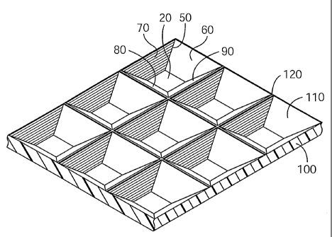
Refernng to FIGS. 11B and 12, in the coating method according to the
invention, the structured release liner 100 is oriented at a bias relative to
the leading
edge 1230 of the liquid adhesive 1210 so as to minimize entrapping air bubbles
between the release liner 100 and the adhesive. The structured release liner
100
includes structures 110 that axe shaped to reduce air bubble formation during
coating
operations. The release liner 100 can include skewed square pyramidal
depressions
110, in which each depression has two sidewalk 60 (not shown in FIG 11B) and
70
that make a relatively shallow angle (3 (not shown in FIG 12) with respect to
the plane
of the surface 120 of the release liner 100 and two sidewalls SO and 90 (not
shown in
FIG 11 B) that make an angle a (not shown in FIG 12) that is relatively steep
with
respect to the plane of the surface 120 of the liner 100. Referring to FIG 12,
the release
liner 100 is oriented so that the lateral edge 50 between sidewall 60 and
sidewall 70 of
structure 110 is substantially perpendicular to the leading edge 1230 of the
rolling bank
of liquid adhesive solution 1210.
Referring again to FIGS. 11A and 11B, as liquid adhesive solution 1210 is
applied to the structured surface 102 of the release liner 100, the adhesive
solution 1210
flows in a direction C into the depressions 110 (not shown in FIG 11A) in the
13
CA 02532348 2006-O1-12
WO 2005/014750 PCT/US2004/017939
structured release liner 100. Referring to FIGS. 11B and 12, the liquid
adhesive 1210
passes over the relatively shallow sidewalls 60 (not shown in FIG 11B) and 70,
flows
over land area 20, and then flows up the relatively steep sidewalls 80 and 90
(not
shown in FIG 11B). The adhesive solution 1210 advances in a direction C to
coat the
entire surface of the liner 100 and create a substantially continuous adhesive
layer
thereon. Referring to FIG 11B, at high coating speeds, as the leading edge
1230 of the
liquid adhesive 1210 advances over structure 110, air bubbles may become
trapped in
an area 40 at the front of the structure 110. In addition, as the leading edge
1230
advances over the structure 100 and begins to fill in the land area 20, air
bubbles may
also become trapped at an area 42 at the back of the structure 110. By
orienting the
structured release liners of the invention so that shallower sidewall angles
are presented
at a bias relative to the leading edge of the adhesive solution first,
followed by steeper
sidewall angles, air bubbles are less likely to be entrapped in the final
adhesive backed
article. Since less air is entrapped in areas around the features during
coating, these
release liners may be coated at higher speed than conventional structured
release liners.
~nce the pressure sensitive adhesive layer is coated onto the release liner,
it
may be laminated to a backing layer to provide an adhesive backed article. The
backing may be a film or a rigid substrate. Examples of suitable films include
metal
films, polymer films such as polyester (PET), polyolefin (polypropylene or
polyethylene), polyvinyl chloride, ethylene-propylene-dime monomer rubber,
polyurethanes, polymethyl methacrylate, engineering thermoplastics (e.g.,
polyphenylene
oxide, polyetheretherlcetone, polycarbonate), thermoplastic elastomers, paper,
nonwoven
webs, or another non-structured release liner. Examples of rigid substrates
include
glass, metals, plastic, wood, ceramic substrates, sign faces, painted surfaces
of these
substrates, and the like.
The invention will now be described with reference to the following non-
limiting examples.
14
CA 02532348 2006-O1-12
WO 2005/014750 PCT/US2004/017939
EXAMPLES
These examples are merely for illustrative purposes and are not meant to limit
the scope of the appended claims. All parts, percentages, ratios, etc. in the
examples
and the rest of the specification are by weight unless indicated otherwise.
Table of Abbreviations
Abbreviation or TradeDescription
Name
COMPLY 20C30 Commercially available paper liner
with structured I
PE coating; 3M Com any, St. Paul,
MN
COMPLY 150C30 Commercially available paper liner
with structure
PE coating; 3M Com ally, St. Paul,
MN
PSA-1 Iso-octyl acrylate/acrylic acid (93/7)
copolymer
blended with 14% by weight of NIREZ
2019 as a
27% solids solution in ethyl acetate
and heptane
mixture.
Prespace Tape 3M Prespace Tape SCPS-55, commercially
available from 3M Com any, St. Paul,
MN
PET Film Polyester (polyethylene terephthalate)
film having a
thickness of 38 micrometers (1.5 mils
NIREZ 2019 Terpene phenolic tackifier resin,
commercially
available from Arizona Chemical, Panama
City, FL
180° Peel Adhesion Test
This peel adhesion test is similar to the test method described in ASTM D 3330
(Test Method A), substituting a glass substrate for the stainless steel
substrate described
in the test. PET/adhesive/Microstructured liner tape constructions were cut
into 2.54
centimeter by 15 centimeter strips. The release liner was removed and each
strip was
adhered to a 15 centimeter by 30 centimeter glass plate (cleaned with 1
diacetone
alcohol and 3 ethanol washes, then dried) using a 2-kilogram roller passed
twice over
the strip. The bonded assembly dwelled at room temperature for one hour and
was
tested for 180° peel adhesion using an IMASS slip/peel tester (SP2000,
commercially
available from Instrumentors Inc., Strongsville, OH) at a rate of 30.4
centimeters/minute (12 inches/minute) over a five second data collection time.
Four
examples were tested for each sample; the reported peel adhesion value is an
average of
the peel adhesion values for the four examples.
15
CA 02532348 2006-O1-12
WO 2005/014750 PCT/US2004/017939
Prespace Tape Adhesion Test
Samples of the Prespace Tape were laminated to the liner to be tested with a
roll
pressure of 414 KiloPascals (60 psi). Test samples of 5.1 centimeters (2
inches) width
were cut and peeled using the 180° Peel test method described above.
Tests were run
immediately (one hour dwell; listed as initial test), after aging under CTH
(constant
temperature (21 °C) and humidity (50% relative humidity)) for 1 day
(listed as 1 day at
CTH), and at 50°C for 5 days (listed as 5 days at 50°C).
Air Bleed Test
Square tape samples (PET/adhesive/Microstructured liner constructions) of 15.2
centimeters x 15.2 centimeters (6 inch x 6 inch) were cut. The liners were
removed and
the exposed tape sample was applied to a platen, which has 2 concentric
grooves cut
into it and adhered by applying a 1235 gram (2.7 pound) roller. Air is
supplied to the
outer groove via an inlet, which has a meter to measure pressure of air
supplied. Air
travels from the outer groove through chamzels in the adhesive to the inner
groove and
pass through an outlet hole in the firmer groove to a flow-meter, which
measures the
airflow through this outlet hole. Airflow was measured at 3 different air
pressures,
either 508, 1016 and 1270 Kilograms/meter2 (20, 40, 50 inches of water) or
508, 1016
and 1905 I~ilograms/meter2 (20, 40, 75 inches of water) and the airflows were
recorded
in milliliters per minute.
Wetout Test
Tape samples (PET/adhesive/Microsti-uctured liner constructions) of area 5.1
centimeters2 were applied backing side down to a flat disk that contained an
epoxy
adhesive that upon curing resists deformation. After curing the liner was
removed to
expose the microstructured adhesive. The disk was mounted such that the
microstructured adhesive faced a probe tip of area 2.32 millimeters2 normal to
the
adhesive face. The probe tip is motuzted to a transducer that accurately
measures the
contact force. The disk and adhesive sample were transparent so that a camera
mounted to the backside of the sample could record the approach, contact and
wetout
when the probe tip was moved toward the sample. Complete wetout is taken to be
the
point at which the adhesive has a uniform appearance over the probe tip
contact area
16
CA 02532348 2006-O1-12
WO 2005/014750 PCT/US2004/017939
and the microstructuring is no longer visible. The displacement (in
micrometers) and
force (in grams) at this point is reported as the wetout value.
Liner Preparation
Microstructured liners were prepared on CONTROLTAC PE coated paper liner.
In addition, two commercially available 3M products were also evaluated and
their
descriptions are outlined in Table A. Angles for each sidewall are listed as
a, (3, y, and
b. Note that the two standard liners (COMPLY 20C30 and COMPLY 150C30) have a"
four angles of 30°, whereas the liners of the invention have variable
sidewall angles.
As a result, asymmetry is introduced. All liners were made so that the
microstructuring
is at a 45° bias to the machine direction of the liner.
Table A
Liner LPI Pitch a ~i y
(~.m)
20C30 20 1270 30 30 30 30
Liner 20 1270 60 30 30 30
A
Liner 20 1270 60 30 60 30
B
150C30 150 169 30 30 30 30
Liner 146 174 60 10 10 10
C
Liner 146 174 60 10 60 10
D
LPI = Lines per inch
Examples 1-8 and Comparative Examples Cl-C2
Tape samples were prepared by knife coating solutions of PSA-1 onto Liners A
and B and commercial liner COMPLY 20C30 to yield 8.6 grains/(2 inch x 12
inch),
equivalent to about 1.5 mils thickness. The liners were coated with either the
30°/30°,
60°/30°, or 60°/60° sidewall slopes leading at a
speed of either 9.1 meters per minute
(30 feet per minute) or 27.4 meters per minute (90 feet per minute) as shown
in Table
1. The coated liners were dried at 88°C (variable residence time
depending on line
speed) and laminated to PET film to provide PET/adhesive/lVlicrostructured
liner
constructions. The liners were removed from these constructions and
180° Peel tests
were run using the test method described above, the results are shown in Table
1.
17
CA 02532348 2006-O1-12
WO 2005/014750 PCT/US2004/017939
Table 1
Example Liner Leading Edge Coating Speed 180 Peel
(meters/minute)(N/dm)
C1 COMPLY 20C30 30/30 9.1 54.7
C2 COMPLY 20C30 30/30 27.4 54.7
1 Liner A 30/30 9.1 63.5
2 Liner A 30/30 27.4 63.5
3 Liner A 60/30 9.1 62.4
4 Liner A 60/30 27.4 62.4
Liner B 30/30 9.1 63.5
6 Liner B 30/30 27.4 61.3
7 Liner B 60/60 9.1 59.1
8 Liner B 60/60 27.4 60.2
Examples 9-20 and Comparative Example C3-CS
5 Tape samples were prepared by knife coating solutions of PSA-1 onto the
Liners C and D and commercial liner COMPLY 150C30 to yield 8.6 grains/(2 inch
x
12 inch) - equivalent to about 1.5 mils thickness. The liners were coated with
either the
30°/30°, 10°/10°, 60°/10° or
60°/60° sidewall slopes leading at a speed of either 1.5
meters per minute (5 feet per minute), 9.1 meters per minute (30 feet per
minute) or
18.2 meters per minute (60 feet per minute) as shown in Table 2. The coated
liners
were dried at 88°C (variable residence time depending on line speed)
and laminated to
PET film to provide PET/adhesive/Microstructured liner constructions. The
liners were
removed from these constructions and 180° Peel tests were run using the
test method
described above, the results are also shown in Table 2.
18
CA 02532348 2006-O1-12
WO 2005/014750 PCT/US2004/017939
Table 2
Example Liner Leading Edge Coating Speed 180 Peel
(metershninute)(N/dm)
C3 COMPLY 150C30 __ 1.5 49.2
30/30
C4 COMPLY 150C30 30/30 9.1 48.1
C5 COMPLY 150C30 30/30 18.2 35.0
9 Liner C 10/10 1.5 64.5
Liner C 10/10 9.1 58.0 I
11 Liner C 10/10 18.2 64:5
12 Liner C 60/10 1.5 61.3
13 Liner C 60/10 9.1 60.2
14 Liner C 60/10 18.2 61.3
Liner D 10/10 1.5 64.5
16 Liner D 10/10 9.1 58.0
17 Liner D 10/10 18.2 60.2
18 Liner D 60/60 1.5 59.1
19 Liner D 60/60 9.1 64.5
Liner D 60/60 18.2 60.2
Examples 21-24 and Comparative Examples C6-C7
5 Samples of the liners A-D and the commercial liners COMPLY 20C30 and
COMPLY 150C30 were tested for Prespace Tape Adhesion according to the test
method described above. The results are shown in Table 3.
Table 3
Example Liner Initial 1 day at CTH 5 days at
(N/dm) (N/dm) 50C
(N/dm)
C6 COMPLY 20C30 0.60 1.23 6.47
21 Liner A 0.75 1.62 5.78
22 Liner B 0.40 0.87 2.96
C7 COMPLY 150C30 0.13 0.33 0.44
23 Liner C 0.54 1.12 5.33
24 Liner D 0.39 0.67 2.23
19
CA 02532348 2006-O1-12
WO 2005/014750 PCT/US2004/017939
Examples 25-28 and Comparative Examples C8-C9
Tape samples described in previous examples were tested for Air Bleed
according to the test method described above. The results are shown in Table
4.
Table 4
Example Example Air Flow Air Flow Air Flow Air Flow
Tape at at at at
air pressureair pressureair pressureair pressure
508 Kg/m2 1016 Kg/m2 1270 Kg/m2 1905 Kg/mz
(ml/min) (ml/min) (ml/min) (ml/min
C8 C1 6 16 NM 41
25 3 6 14 NM 33
26 7 4 9 NM 22
C9 C3 16 44 75 NM
27 9 5 23 41 NM
28 15 8 32 50 NM
N1V1= not measured
Examples 29-30 and Comparative Example C10
Tape samples described in previous examples were tested for Wetout according
to the test method described above. The results are shown in Table 5.
Table 5
Example Example Tape Force at WetoutDisplacement
(grams) at
Wetout
(micrometers)
C10 C3 187 15.0
29 9 115 6.4
30 15 184 9.8
A number of embodiments of the invention have been described. Nevertheless,
it will be understood that various modifications may be made without departing
from
the spirit and scope of the invention. Accordingly, other embodiments are
within the
scope of the following claims.