Note: Descriptions are shown in the official language in which they were submitted.
CA 02532414 2006-01-12
WO 2005/027714
PCT/US2004/022025
SENSITIVE AND RAPID BIODETECTION
Technical Field
The present invention relates to the detection of biological targets by
reacting the targets with
probes immobilized on surfaces.
Background
Conventional biodetection utilizes immobilized probes to detect targets in
solution. Such systems
often include DNA probes to detect DNA and RNA targets, antibody probes to
detect proteinaceous,
carbohydrate, and small organic molecule targets, and aptamer probes to detect
nucleic acid, proteinaceous,
carbohydrate, and small organic molecule targets. These systems can include
conventional ELISA (an
enzyme-linked immunosorbent assay) that can take place in a macrowell format
(e.g. a microtiter well), as
well as microarray formats in which the immobilized probes can be constructed
or "printed" in spots less
than a hundred microns in diameter. Such methods are extensively practiced
today in clinical and research
applications (see, for example, US Patent #5,405,783 to Pirrung, et. al., US
Patent # 6,054,270 to Southern,
US Patent #6,101,946 to MartinsIcy, and Weeraratna et al. "Gene Expression
Profiling: From Microurays to
Medicine", ./. Clin. Immunol. 24:213 (2004), the "Packard Biochip Arrayer"
from Perkin Elmer, Wellesley,
MA).
In all of these methods, there is a binding reaction between the probe and the
target, and this
binding reaction is generally governed by the reaction kinetics of multiple
reactant (generally bi-molecular)
systems. Because the probes are immobilized, the rate of reaction is primarily
determined by the
concentration of the target in solution.
In many of the systems, the rate of the reaction is important. For example, in
certain nucleic acid
hybridizations, the reaction can require over 48 hours to complete, which can
increase the cost of the
analysis, or reduce the number of analyses that can take place. Furthermore,
if not all of the hybridizations
react to completion, then the quantitation of the analyses can be incorrect,
mixing as it would the results
form hybridizations at different levels of completion.
In an important application, the medical outcomes of human infections (e.g.
ventilator acquired
pneumonia, infectious meningitis, bacteremia, and the like) can be
significantly affected by the length of
time required to perform analysis of the amount and the identity of bacteria
and the susceptibility of the
bacteria to various antibiotics. Conventionally, the time for analysis can be
24 to 48 hours or more, during
which time the condition of the patient can deteriorate as the bacteria
multiply (see, for example, US Patent
#4,778,758 to Ericsson et al., US Patent #3,935,073 to Waters, US Patent
#6,043,048 to Johnston et al., and
US Patent #4,259,442 to Gayral). Contemporary microbial analysis starts with
growth of bacteria from a
clinical specimen, such as sputum, blood, and the like, to high concentration
in culture medium, typically
on the order of 100 million organisms per milliliter. Clinical specimens may
contain only a few individual
organisms (e.g. in testing blood for bacteremia), and diagnostic thresholds
even for high-concentration
specimens are typically several thousand-fold lower than quantitative
culturing detection limits.
After achieving initial bulk growth up to an adequate working concentration,
the operator then
performs one or more biochemical tests or growth on selective media that
incorporate selective biochemical
CA 02532414 2006-01-12
WO 2005/027714
PCT/US2004/022025
2
reagents. Thus the standardized current procedures require at least two
sequential growth cycles, each
typically requiring many hours to complete.
Additionally, drug susceptibility testing requires determination of failure to
grow in selective
media. Proof of the absence of growth requires additional time in culture over
that which might be required
of a direct indicator of cell death. It is well recognized in the medical
community that such methods,
attempting to prove the absence of growth, in certain circumstances produce
results that do not correlate
adequately with the actual results of treatment.
As a result of these and other serious deficiencies, contemporary practice
fails to provide the
attending physician with specific diagnostic information that the physician
needs in order to select an
effective drug to treat the infection within the desired time window. For
example, in ventilator-associated
pneumonia, clinical research has demonstrated that the odds ratio for
increased morbidity and mortality
after 24 hours of ineffective treatment remains at 7:1 despite a change to
effective treatment. That is, unless
the physician initiates effective treatment, i.e. anti-microbial drugs of a
type and concentration adequate to
quickly kill the infectious organisms, within substantially less than 24 hours
from symptom onset, a change
from ineffective to effective therapy will not significantly improve outcomes
for approximately 87% of
patients so treated.
Physicians are well aware of the risk of delay, and so prescribe treatment
typically using a
combination of broad-spectrum drugs selected empirically, based on a
particular hospital or community
history of microbial drug resistance or susceptibility. Clinical research has
demonstrated that such empiric
drug treatment is ineffective in approximately 25% to 50% of cases.
Additionally, exposure of a patient to
inadequate therapy not only increases the individual patient's costs and
medical risks, but also increase the
likelihood of fostering the emergence of resistant organisms. The latter
problem increases the medical risk
not only for the individual patient, but for all other individuals in the
hospital and community who may later
become infected with resistant organisms.
It is well recognized in the clinical research literature that prior exposure
of a patient to ineffective
antibiotics constitutes a significant risk factor in the later emergence of
resistant organisms in that patient.
For these and other reasons, it is desirable within the medical community to
devise diagnostic methods that
do not suffer the deficiencies of delay and inaccuracy that characterize
current practices.
In theory, alternatives to microbial growth culturing include direct microbial
analytical methods
such as immunoassays of various kinds. Antibodies against various microbes are
commercially available or
may be readily developed. In fact, many different types of immunoassay are now
routinely used in certain
aspects of diagnosis for microbial infection.
However, none yet exist for routine bacterial identification, quantitation,
and drug susceptibility
testing for many serious infectious diseases.
Similarly, the rapid detection of various microbes such as bacteria, viruses,
molds, and the like are
also desirable for testing contamination in food and water, and in detecting
the presence of potential
biological warfare agents. In the food industry many products are commercially
available for detecting
microbial contaminants. In certain circumstances, some of these provide
results in approximately 24 hours
for a limited set of particular organisms. However all commercial products
still require sample enrichment
by means of bacterial culturing before applying the tests.
CA 02532414 2006-01-12
WO 2005/027714
PCT/US2004/022025
3
In the research literature concerning defense for biological warfare, many
rapid detection devices
have also been described, including some that provide results in one hour or
even less. Furthermore, some
such devices do not require growth cultures before being used.
However, the sensitivity of devices so far described in the literature for
food testing or bio-defense
falls far short of the requirements for medical diagnostics. Furthermore,
these non-diagnostic applications
do not require drug susceptibility testing and so the aforesaid devices do not
provide it nor apparently do
they lend themselves to adaptation for such a purpose.
A key limitation with these devices and with laboratory methods such as ELISA
is the their
dependency on the target analyte concentration. They rely on passive diffusion
of target to an immuno-
capture or other detection surface. The rate of occurrence of intimate probe-
to-target proximity events, and
hence the detection reaction rate, depends on analyte concentration in the
sample solution or suspension.
In order to increase sensitivity with these devices, it is necessary to
substantially increase analyte
concentration. Researchers have described several strategems to increase
target analyte concentration and
also speed the response time for analysis of various bio-molecular and
microbial targets. For example, the
electrophoresis of target to the probe has been described before by Nanogen,
Inc. of San Diego, CA (e.g.
US Patent #5,849,486 to Heller, US Patent #6,017,696 to Heller, US Patent
#6,051,380 to Sosnowski et al.,
US Patent #6,099,803 to Ackley et al., US Patent #6,245,508 to Heller et al.,
and US Patent #6,379,897 to
Weidenhammer et al.). These systems and methods describe an addressable array
of electrodes to which
individual probes are attached at each individual electrode, and then which
are sequentially and very rapidly
reacted with probes. The reported increase in speed of reaction between the
target and probes is hundreds
or thousands fold. These systems, however, suffer from a number of
limitations, including the need to
sequentially immobilize probes on the addressable electrodes, the need to
perform sequential reactions, and
limitations on the detection methods that can be employed due to the higher
voltages that are required for
electrophoresis, precluding the use of transparent electrodes (e.g. through
the use of indium tin oxide), that
cannot operate at the voltages used by the Nanogen system. Furthermore, the
higher voltages at which the
Nanogen system operate generate oxidation products that are potentially
harmful to the probes or targets,
and which therefore requires the use of complex passivation surfaces to
protect the probes and targets.
Systems that could make use of high-speed microarray printing, which did not
require complex passivation
surfaces, and which did not require the electronic and other control necessary
for addressable electrodes
would greatly reduce the expense and complexity of such systems.
With regards to the use of immobilized probes for the detection of bacteria or
other
microorganisms, it is also of use to determine the antimicrobial activity of
different therapeutic agents, such
as antibiotics. There has been a profusion of systems that use nucleic acid or
antibody probes to determine
the identity of bacteria in a sample (e.g. US Patent #5,656,432 to Claverys et
al. and US Patent #6,403,367
to Cheng et al.). It is difficult with these systems to determine
susceptibility to antimicrobial agents, given
the difficulty of finding nucleic acid or antibody markers that reliably
correlate with antimicrobial
resistance or behavior.
It is to the solution of these and other problems that the present invention
is directed.
CA 02532414 2015-09-28
= CA2532414
3a
Summary of the Invention
Various embodiments disclosed herein relate to a system for detecting a first
type of viable
microorganism in a solution, comprising: a chamber comprising a first
electrophoresis electrode and a second
electrophoresis electrode on opposing walls of the chamber, wherein the
electrodes are configured to cause
said microorganism to migrate toward said first electrode when a potential is
applied between the electrodes; a
first capture surface disposed on said first electrode, said capture surface
comprising a plurality of first capture
agents that bind to said first type of viable microorganism, wherein said
first type of viable microorganism is a
microorganism that engages in growth and division; an electrode controller
operably linked to the first and
second electrodes, said controller configured to control the potential between
the first and second electrodes;
and an optical detector configured to detect the quantity of said first type
of viable microorganism bound to the
first capture agents.
Various embodiments disclosed herein relate to a method of detecting a first
type of viable
microorganism in a solution, comprising introducing the first type of viable
microorganism to a system
comprising: a chamber comprising a first electrophoresis electrode and a
second electrophoresis electrode on
opposing walls of the chamber, wherein the electrodes are configured to cause
said microorganism to migrate
toward said first electrode when a potential is applied between the
electrodes; a first capture surface disposed
on said first electrode, said capture surface comprising a plurality of first
capture agents that bind to said first
type of viable microorganism, wherein said first type of viable microorganism
is a microorganism that engages
in growth and division; an electrode controller operably linked to the first
and second electrodes, said
controller configured to control the potential between the first and second
electrodes; and an optical detector
configured to detect the quantity of said first type of viable microorganism
bound to the first capture agents;
capturing the microorganism on the first capture surface using an applied
force, wherein the surface has an
affinity for the microorganism and the applied force is electrophoresis;
detecting at a first time a property of
the microorganism on the surface; placing the microorganism in a condition;
detecting at a second time the
property of the microorganism on the surface; and determining the response of
the microorganism to the
condition by the amount of difference of the property of the microorganism
between the first time and the
second time.
Various embodiments disclosed herein relate to a method of detecting the
response of a test
microorganism to a condition, comprising: capturing the microorganism on a
surface of a substrate using an
applied force, wherein the surface has an affinity for the microorganism;
detecting at a first time a property of
the microorganism on the surface; placing the microorganism in the condition;
detecting at a second time the
property of the microorganism on the surface; and determining the response of
the microorganism to the
condition by the amount of difference of the property of the microorganism
between the first time and the
second time.
Various embodiments disclosed herein relate to a method for the identification
of microorganisms in
a sample comprising: contacting a sample with a device comprising a chamber
and at least one capture surface;
CA 02532414 2015-09-28
= CA2532414
3b
capturing microorganisms on the capture surface, wherein an individual
microorganism binds to the capture
surface at a spatially discrete location; introducing a first indicator to the
device, wherein the first indicator is
configured to bind to a first type of microorganism; and detecting the
presence of the first indicator.
Various embodiments disclosed herein relate to a system for the identification
of individual
microorganisms in a sample comprising: an enclosed chamber comprising: a first
electrode disposed on a
detection surface, wherein the first electrode is a transparent conductive
surface; a second electrode disposed
on a second surface; an input port configured to transport a fluid into the
chamber; an output port configured to
transport the fluid out of the chamber; and a capture surface disposed on the
first electrode, wherein the capture
surface comprises a binding agent configured to bind the individual
microorganisms; an electrical controller
operably linked to the first and second electrodes and configured to control
the potential between the first and
second electrodes; an optical detector configured to detect the individual
microorganisms bound to the capture
surface; and a storage controller configured to perform analysis of an image
obtained by the optical detector.
Various embodiments disclosed herein relate to a method for the detection of a
first type of
microorganism in a sample comprising: a) contacting said sample with a system
comprising: i) a chamber
comprising a first electrode and a second electrode on opposing walls of the
chamber, wherein the electrodes
are configured to cause said microorganism to migrate toward said first
electrode when a potential is applied
between the electrodes; ii) a first detection surface disposed on said first
electrode, said surface comprising a
plurality of first affinity components that bind to said first type of
microorganism; iii) an input port configured
to transport said solution into the chamber between the electrodes; iv) an
output port configured to transport
said solution out of said chamber; v) an electrical controller operably linked
to the first and second electrodes,
said controller configured to control the potential between the first and
second electrodes; vi) an automated
detector configured to detect the quantity of said first type of microorganism
bound to the first affinity
components; vii) an information controller that stores the quantity of the
first type of microorganism as
determined by the automated detector; b) capturing said microorganism onto
said detection surface, wherein a
plurality of said microorganisms bind to said detection surface in; c)
allowing said microorganisms to grow;
and d) detecting a quantity of said microorganisms as an indication of the
presence of said microorganism in
the sample.
Various embodiments disclosed herein relate to a method for detecting the
response of at least a first
type of microorganisms to a condition in a sample comprising: a) contacting
said sample with a system
comprising: i) a chamber comprising a first electrophoresis electrode and a
second electrophoresis electrode on
opposing walls of the chamber, wherein the electrodes are configured to cause
said first type of microorganism
to migrate toward said first electrode when a potential is applied between the
electrodes; ii) a first detection
surface disposed on said first electrode, said surface comprising a plurality
of first affinity components that
bind to said first type of microorganism; iii) an input port configured to
transport said solution into the
chamber between the electrodes; iv) an output port configured to transport
said solution out of said chamber; v)
an electrical controller operably linked to the first and second electrodes,
said controller configured to control
CA 02532414 2016-07-14
CA2532414
=
3c
the potential between the first and second electrodes; vi) an automated
detector configured to detect the
quantity of said first type of microorganism bound to the first affinity
components; vii) an information
controller that stores the quantity of the first type of microorganism as
determined by the automated
detector; b) capturing said microorganism onto said detection surface, wherein
a plurality of said
microorganisms bind to said detection surface; c) detecting at a first time
property of said
microorganisms on the surface with the automated detector; d) adding at least
one condition to said
detection surface; e) detecting at a second time a property of said
mircoorganisms on the surface with the
automated detector; 0 determining the response of the mircoorganisms to the
condition by the amount of
difference of the property in the mircoorganisms between the first time and
the second time.
Various embodiments disclosed herein relate to a method of detecting growth of
a
microorganism in a sample comprising: contacting a sample comprising a
microorganism with a device
comprising chamber, wherein the chamber comprises a detection zone, and
wherein the detection zone
further comprises a hydrogel; immobilizing the microorganism by capture with
the hydrogel; detecting at
a first time a property of the microorganism with an optical detector;
detecting at a second time the
property of the microorganism with the optical detector; and determining the
amount of difference of the
property of the microorganism between the first time and the second time.
Various embodiments disclosed herein relate to a method of detecting growth of
a
microorganism in a sample comprising: contacting a sample comprising a
microorganism with a device
comprising a chamber; allowing the microorganism to grow for a first period of
time; and detecting growth of
the microorganism as an indication of the presence of the microorganism,
wherein growth of the
microorganism is detected using a non-optical detection method.
The claimed invention relates to a system for detecting a first type of viable
microorganism in a solution, comprising: a chamber comprising a first
electrophoresis electrode and a
second electrophoresis electrode on opposing walls of the chamber, wherein the
electrodes are
configured to cause said first type of viable microorganism to migrate toward
said first electrode when a
potential is applied between the electrodes; a first capture surface disposed
on said first electrode, said
capture surface comprising a plurality of first capture agents that bind to
said first type of viable
microorganism, wherein said first type of viable microorganism is a
microorganism that engages in
growth and division; an electrode controller operably linked to the first and
second electrodes, said
controller configured to control the potential between the first and second
electrodes, wherein application
of the potential during growth of said first type of viable microorganism
causes new microbial offspring
to associate close to a location on the first capture surface of the first
type of viable microorganism from
which the new microbial offspring are derived; and an optical detector
configured to detect a quantity of
said first type of viable microorganism bound to the first capture agents.
Also claimed is a method
employing such a system for detecting the first type of viable microorganism
which comprises
application of the potential during growth of the first type of viable
microorganism to cause new
microbial offspring to associate close to a location on the first capture
surface of the first type of viable
microorganism from which the new offspring are derived and detecting the
quantity of the first type of
viable microorganism bound to the first capture agents using the optical
detector.
CA 02532414 2014-07-17
4
In light of the deficiencies of existing biodetection systems and methods, it
is an objective to
perform detection of biological molecules rapidly.
It is additionally an object of this invention to minimize non-specific
binding that reduces the
sensitivity of biodetection.
It is also an object of this invention to be able to distinguish specific from
non-specific binding of a
target to a surface.
It is another object of this invention to be able to identify microorganisms
and to determine their
susceptibility to anti-organism agents.
It is further an object of this invention to capture probes rapidly onto a
surface in order to permit
their detection.
Additional objects, advantages and novel features of this invention shall be
set forth in part in the
description that follows, and in part will become apparent to those skilled in
the art upon examination of the
following specification or may be learned by the practice of the invention.
The objects and advantages of
the invention may be realized and attained by means of the instrumentalities,
combinations, and methods
particularly pointed out in the appended claims.
In summary, the invention comprises processes and components that can be used
singly or in
combination for beneficial effect. The resulting methods and devices can be
used in the biodetection of a
variety of different analytes within a sample, including nucleic acids,
proteins, starches, lipids, and
organisms and cells. In the most general forms, these entities are captured
onto a substrate, where they are
detected.
One aspect of the present invention involves the detection of microorganisms
on a fixed substrate
at more than one time. Changes in the conditions of the microorganisms at the
different times can indicate
their response to agents to which the microorganisms are exposed. The
conditions of the bacteria can
include their appearance with various stains, such as vital and mortal stains,
or the appearance of growth in
the microorganism, either through its size, ability to accept additional
staining agent, or the occurrence of
nearby "daughter" microorganisms that indicate the doubling of the
microorganisms. More generally, the
condition can include the identity of the microorganism, as might be indicated
by a serological stain. The
agents can include a variety of different antibiotics, which can be provided
to the microorganisms at a
number of different concentrations in order to determine properties of the
bacteria such as the minimum
inhibitory concentration or the minimum bacteriocidal concentration. The
microorganisms can be
challenged not only with constant concentrations of the agent, but the agent
can also be exposed to a
varying concentration that can mimic the phannacolcinetics of the agent.
It should be noted that looking at the growth and behavior of individual
microorganisms has great
beneficial effect, given that most current means of monitoring microorganisms
requires a large number of
microorganisms, and it can take an extended period to grow to sufficient
numbers of microorganisms. By
monitoring individual microorganisms, it is not even required for all of the
individual microorganisms to
show the effect, but only for a sufficient fraction so that the effect is
demonstrated over a statistical
background. This can allow for a very rapid test.
CA 02532414 2006-01-12
WO 2005/027714
PCT/US2004/022025
Another aspect of the present invention is the movement of the microorganisms
or other analytes
to a substrate where they can be captured. This movement can comprise a number
of different forces,
including electrophoresis, dielectrophoresis, centrifugation, magnetic field
capture, filtration, gravity or
diffusion. In many instances, the naturally occurring forces of gravity and
diffusion are not strong enough
5 for the movement to occur in a practical time for the test, and therefore
the application of other artificial
forces are necessary. The forces can act either directly on the analyte, or
the analyte can be bound to a tag
that responds to the application of the artificial force. The tag can comprise
an electrostatic tag, which can
include a polyelectrolyte, which then moves in an electrophoretic or
dielectrophoretic field. The tag can
also comprise a paramagnetic particle that responds to a magnetic field.
A further aspect of the present invention is to use a movement of the analyte
with a component
parallel to the surface where the analyte is captured either at the same time
as or interspersed with the
movement of the analyte towards the surface. This allows the analyte to become
distributed along the
surface, and can further allow for a larger fraction of the analyte to bind
where there are multiple regions of
potential binding. If these regions have different specificity for different
species of analyte within the
sample, then this allows the analyte to be moved from region to region until
it contacts the region with the
matching specificity. The movement parallel to the surface can comprise
electrophoresis, filtration, or bulk
flow (which can be instituted, for example, by pumps, electroosmosis, or other
means).
Another aspect of the present invention is to tag the analyte with an
indicator that confers
detectability on the analyte. The indicator can comprise a light scattering
particle, an enzyme-containing
particle, a fluorophore, an upconverting phosphor, a quantum dot, or an
electrochemical agent. It can also
be very useful to have a tag that confers both detectability as well as
movement with an artificial force (as
described above).
A yet further aspect of the present invention is to remove analyte that is non-
specifically bound to
the surface. This washing can utilize the same forces that move the analyte
towards the surface, but now
applied in another direction. Such forces can include electrophoresis,
dielectrophoresis, and magnetic
forces. The forces can also comprise physical and chemical conditions such as
pH, ionic strength, and bulk
flow (laminar or otherwise).
It is also an aspect of the present invention that there be frequent
monitoring of the analyte on the
surface. For example, it is preferable for there to be a number of different
stringencies of removal of the
non-specifically bound material, so that specifically-bound material can be
distinguished both from non-
specifically-bound material that is less-forcefully bound as well as from
material that is more-forcefully
bound. The frequent monitoring can then identify specifically-bound material
by looking at the stringency
at which different material is removed form the surface.
An aspect of the present invention is monitoring in real-time using optical
methods, which can not
only identify the presence of an analyte on the surface, but also to store the
location of individual analytes
on the surface so that its presence can be monitored over time. The optical
detection can comprise imaging
detectors, such as a camera, but can also comprise a scanning laser with a
light detector, that can be a photo
multiplier tube. The detector can detect either the analyte itself, or as
described above, an indicator that is
bound to the analyte. The detector can comprise a brightfield, darkfield,
phase, fluorescent, or other
CA 02532414 2006-01-12
WO 2005/027714
PCT/US2004/022025
6
emitted light detector. Alternatively, the detector can comprise a surface
plasmon resonance detector,
wherein the surface comprises gold.
An additional aspect of the present invention relates to the use of indium tin
oxide and other
transparent conductive coatings which facilitate the use of optical detection.
In these cases, it is necessary
that the voltages that are used not exceed on the order of 2 Volts, which
potential does not support
electrophoresis and dielectrophoresis with many conventional buffers. It can
be convenient to use redox
reagents in order to support electrophoresis and dielectrophoresis. These
redox reagents can be in pairs, in
which the oxidation of the reducing agent gives rise to the oxidizing agent,
and the reduction of the
oxidizing agent gives rise to the reducing agent. Other arrangements are also
possible, for example in
which the oxidation product of the reducing agent oxidizes the reduction
product of the oxidizing agent. It
is also convenient for these reagents to be neutrally charged, so that ionic
species do not interfere with the
electrophoresis and dielectrophoresis.
It is yet an additional aspect of the present invention for the solutions in
which electrophoresis and
dielectrophoresis occur to have low ionic strength, so that the electrolytes
do not reduce the effectiveness of
the electrophoresis. In these cases, it is convenient for the solutions to
comprise zwifterionic species both
for buffering, for stabilizing the interactions between molecular species, and
for providing a growth
conducive environment for microorganisms.
Another aspect of the present invention is for the illumination comprises
evanescent wave
illumination, since this detects only that analyte that is juxtaposed with the
surface, and thus analyte or
indicators that are not bound can remain in the solution above the surface.
The evanescent wave
illumination can be coupled into the substrate beneath the surface using
gratings, end-couplings, and
prisms. While the evanescent wave illumination can bounce multiple times
within the substrate, it is also
convenient for the evanescent wave illumination to have a single bounce
against the surface, which is
conveniently performed with prisms which can be either detachable or
permanently attached or formed with
the substrate. If detachable, the interface between the prism and the
substrate can be a transparent, elastic
material.
A yet further aspect of the present invention is the use of sample
presentation, which can comprise
concentration of the analyte from a large sample volume, as well as removal of
contaminants. This sample
preparation can comprise centrifugation, ion exchange beads or columns,
filtration, stacking
electrophoresis, or forms of biochemical separation.
As described above, numerous embodiments of the present invention can be
assembled from the
these and other aspects of the present invention. For example, one preferred
embodiment resulting from the
combination of aspects of the present invention relates to a system for the
quantitation of microorganisms of
a first type in a solution. This system comprises a chamber comprising a first
electrode and a second
electrode on opposing walls of the chamber, an input port, an output port, and
a fluid transport means for
transporting solution into the chamber through the input port and out of the
chamber through the output
port. The system further comprises a first affinity component affixed to the
first electrode, to which
microorganisms of the first type adhere, an electrical controller that
controls the potential between the first
electrode and the second electrode, an automated detector that can detect the
quantity of microorganisms of
the first type adhered to the first affinity component, and an information
controller that stores the quantity
CA 02532414 2006-01-12
WO 2005/027714
PCT/US2004/022025
7
of microorganisms of the first type as determined by the detector. In the
system, the solution is introduced
into the chamber through the input port, a potential is applied by the
controller between the first and the
second electrodes sufficient to cause electrophoresis to occur between the
electrodes, causing movement of
microorganisms of the first type towards the first electrode to occur, such
that when the microorganisms are
proximate to the first affinity component, they bind to the first affinity
component and their quantity is
determined by the detector and stored in the information controller.
The microorganisms may comprise bacteria selected from a set of genera such as
Pseudomonas,
Stenotrophomonas, Acinetobacter, Enterobacter, Escherichia, Klebsiella,
Proteus, Serratia, Haemophilus,
Streptococcus, Staphylococcus, Enterococcus, Mycobacterium, Neisseria, and
other human pathogens
encountered in medical practice. Similarly, microorganisms may comprise fungi
selected from a set of
genera such as Candida, Aspergillus, and other human pathogens encountered in
medical practice. Still
other microorganisms may comprise human pathogenic viruses encountered in
medical practice.
The oxidizing agent may comprise benzoquinone, a dithiol, a ketone, a
ferrocinium, a ferricyanide,
dihydroascorbate, oxidized glutathione, oxidized methyl viologen, or a
halogen. The reducing agent may
comprise dithiothreitol, dithioerythritol, a dithioalkane, a dithioalkene, a
thioalkane, a thioalkene, a thiol, a
hydroquinone, an alcohol, a ferrocene, a ferrocyanide, ascorbate, glutathione,
methyl viologen, or a halide.
Also, the reduced product of the oxidizing reagent may comprise the reducing
agent.
The conductivity of the solution may be less than 100 microSiemens/cm or the
conductivity of the
solution may be less than 10 microSiemens/cm. The solution may comprise a
zwitterionic buffer.
A concentrator may concentrate the microorganisms from a sample. The
concentrator may
comprise a centrifuge. The concentrator may comprise ion exchange particles.
The sample may have a higher conductivity than the solution.
The automated detector may comprise an optical detector. The optical detector
may utilize optical
detection methods including light scattering imaging, brightfield imaging,
darkfield imaging, surface
plasmon resonance, phase imaging, fluorescence imaging, upconverting phosphor
imaging, quantum dot
imaging, and chemiluminescence imaging.
An electrode selected from the set comprising the first electrode and second
electrode may be
optically transparent.
The target may be illuminated by a laser.
The detector additionally may determine the position of each microorganism
adhered to the affinity
component, wherein the locations of the microorganisms may be stored in the
information controller along
with the quantity of the microorganism at that location.
The detector may detect total amount of microorganisms of the first type
through averaging of
signal of a portion of the surface comprising substantially all of the
microorganisms of the first type affixed
to the first electrode.
The first electrode may be comprised of gold, and the detector may utilize
surface plasmon
resonance.
The detector may comprise a camera.
The field of view corresponding to each pixel may comprise a long axis that is
less than 2 microns,
or may be less than 0.5 microns.
CA 02532414 2006-01-12
WO 2005/027714
PCT/US2004/022025
8
The solution may be in bulk movement during electrophoresis.
Two periods of electrophoresis may be interspersed with a period in which the
solution is in bulk
movement.
The solution additionally may include microorganisms of a second type, wherein
the detector can
distinguish microorganisms of the first type from microorganisms of the second
type.
A first tag may be comprised of a first binding agent linked to a first
indicator that is detectable by
the detector and a second tag may be comprised of a second binding agent
linked to a second indicator that
is detectable by the detector and wherein the first indicator and the second
indicator are distinguishable by
the detector, wherein the first binding agent binds to microorganisms of the
first type, and the second
binding agent binds to microorganisms of the second type, wherein the first
tag and the second tag are
reacted with microorganisms of the first type and microorganisms of the second
type bound to the affinity
component, and the detector substantially simultaneously detects the quantity
of the microorganisms on the
basis of the tags that are bound to the microorganisms.
A first tag may be comprised of a first binding agent linked to an indicator
that is detectable by the
detector and a second tag is comprised of a second binding agent linked to the
indicator, wherein the first
binding agent binds to microorganisms of the first type, and the second
binding agent binds to
microorganisms of the second type, wherein the first tag is reacted with
microorganisms of the first type
bound to the affinity component and the detector detects the quantity and
location of the microorganisms of
the first type on the basis of the tags that are bound to the microorganisms,
and subsequently, the second tag
is reacted with microorganisms of the second type bound to the affinity
component and the detector detects
the quantity and location of the microorganisms of the second type on the
basis of the tags that are bound to
microorganisms that are in locations that were not previously detected by the
detector.
A tag may be comprised of a binding agent linked to an indicator, wherein the
binding agent may
comprise an antibody that binds to microorganisms of the first type.
The detector may distinguish microorganisms of the first type from
microorganisms of the second
type on the basis of differing electrophoretic properties of the
microorganisms.
The first affinity component may comprise a polyelectrolyte. The
polyelectrolyte may comprise a
polycationic polymer. The polycationic polymer may comprise amine moieties.
The polymer may
comprise polyethyleimine or polylysine.
The solution additionally may include microorganisms of a second type, wherein
microorganisms of
the second type do not bind to the first affinity component. The affinity
component may an antibody or an
aptamer.
A second affinity component may be bound to the first electrode, to which
microorganisms of the
second type adhere, wherein the detector can detect the quantity of
microorganisms of the second type
adhered to the second affinity component, wherein the system can distinguish
microorganisms of the first
type from microorganisms of the second type by whether the microorganisms
adhere to the first affinity
component or the second affinity component.
The affinity component additionally may comprise a polymer that has
intrinsically low affinity for
microorganisms, wherein the polymer may comprise polyethylene glycol or
polyacrylamide.
CA 02532414 2006-01-12
WO 2005/027714
PCT/US2004/022025
9
The system may additionally comprise a third electrode, co-planar with the
first electrode, to which
a second affinity component may bind and to which microorganisms of the second
type may adhere,
wherein the potential on the first electrode and the third electrode may be
independently controlled by the
electrical controller.
The detector may detect whether microorganisms of the first type are live or
dead. The
microorganisms may be stained prior to being detected by the detector with a
mortal stain or the
microorganisms may be stained prior to being detected by the detector with a
vital stain. Subsequent to the
microorganisms of the first type adhering to the first affinity component, the
microorganisms may be placed
in conditions conducive to growth. These conditions may comprise temperature
between 34 and 40 degrees
C.
The solution may be removed from the chamber via the output port and may be
replaced by growth
medium through the input port. Also, the growth medium may have a conductivity
of less than 1
milliSiemens/cm, and the electrical controller may maintain a potential of
greater than 100 mV between the
first electrode and the second electrode.
Microorganisms of the first type may be detected by the detector at an initial
time, and may also be
detected at a second time after the microorganisms are allowed growth time
sufficient for at least 10% of
the microorganisms to double, wherein differences in the detected
microorganisms of the first type at the
two may provide evidence of the viability of the microorganisms of the first
type in the growth conditions.
Also, an anti-microorganisms agent may be added to the growth medium during
the growth time. The
detector may detect if microorganisms of the first type are live or dead in
response to the anti-
microorganism agent, wherein prior to detection by the detector the
microorganisms are stained with a stain
selected from the set consisting of mortal stain and vital stain. The anti-
microorganism agent may comprise
individual agents or combinations of agents selected from antibiotic families
such as cephalosporins,
penicillins, carbapenems, monobactams, other novel beta-lactam antibiotics,
beta-lactamase inhibitors,
fluoroquinolones, macrolides, ketolides, glycopeptides, aminoglycosides,
fluoroquinolones, rifampin, and
other families, including novel agents, used as antibiotics in clinical
practice or in research. Also, the
concentration of the anti-microorganism agent may be changed over time to
reflect the pharmacoldnetics of
the anti-microorganism agent in animal tissue.
The microorganisms may be reacted with a surplus of microorganism surface
binding reactants at a
first time period, after which the reactants are subsequently removed, and
wherein at a second time period
the microorganisms may be reacted with a surplus of microorganism surface
binding molecules modified by
an indicator so as to be detectable by the detector, wherein the detection of
the indicator by the detector
indicates the growth of the microorganisms.
The solution additionally may comprise a contaminant that binds to the first
affinity component
along with the microorganisms of the first type, wherein a condition is
applied to the first affinity
component which releases the contaminant without releasing the microorganism,
whereas the contaminant
is removed by application of the condition. The condition may comprise
temperature, magnetic field
strength, electrophoretic force, dielectrophoretic force, shear fluid flow,
ionic strength, pH, non-ionic
surfactant concentration, ionic surfactant concentration, or competitor
concentration. The solution
additionally may comprise a contaminant which binds to the first affinity
component along with the
CA 02532414 2006-01-12
WO 2005/027714
PCT/US2004/022025
microorganisms of the first type, wherein a condition is applied to the first
affinity component which
releases the microorganisms without releasing the contaminant, whereas the
microorganisms may be
subsequently bound to a second affinity component affixed to the first
electrode. The condition may
comprise temperature, magnetic field strength, electrophoretic force,
dielectrophoretic force, shear fluid
5
flow, ionic strength, pH, non-ionic surfactant concentration, ionic surfactant
concentration, or competitor
concentration.
The microorganisms of the first type may be concentrated in the solution prior
to being bound to the
first affinity component, wherein the microorganisms are present in a first
salt buffer of relatively low ionic
strength, and the first salt buffer is proximal to a second salt buffer of
relatively higher ionic strength and
10 the
first salt buffer and the second salt buffer adjoin at an interface, and
wherein a first concentration
electrode is located proximal to the interface and a second concentration
electrode is located distal to the
interface, wherein the placement of a potential between the first
concentration electrode and the second
concentration electrode causes the microorganisms to migrate through the first
salt buffer by electrophoresis
and their migration is reduced more than X fold upon meeting the interface.
The second concentration
electrode may comprise the first electrode. Also, the interface may be located
substantially at the input
port. The ratio of conductivity between the first salt buffer and the second
salt buffer may be less than 1:50.
Brief Description Of The Drawings
Fig. 1 is a schematic diagram of a biodetection system that utilizes a probe
having affinity for a
target.
Fig. 2A, a schematic diagram of a biodetection system taking place in which
different probes 116
are placed in an array of locations on a substrate.
Fig. 2B is a side-view through the array of Fig. 2A.
Fig. 3 is a perspective diagram of an electrophoretically-enhanced incubation
system.
Fig. 4A is a perspective diagram of a biodetection system wherein a single
probe electrode
underlies multiple probe locations which are placed into an array.
Fig. 4B is a perspective diagram of a biotection system wherein the electrodes
do not underlie the
probe locations.
Fig. 5 is a diagram of electric field strengths from a first electrode, a
second electrode, and a set of
partial reference electrodes.
Fig. 6 is a schematic diagram of an electrophoretic tag in a sandwich
configuration.
Figs. 7A through F are schematic diagrams of electrophoretic tags, showing
differing arrangements
of components to provide similar functionality.
Fig. 8 is a schematic block flow diagram of the steps of the present
invention.
Fig. 9 is a graph of the amounts of material bound versus the binding force.
Fig. 10 is a schematic block flow diagram of a system involving electrodes not
underlying probe
locations.
Fig. 11A is a schematic block flow diagram of the operation of a cell
involving electrodes
underlying probe locations, and can be best understood in relation to Fig. 4A.
CA 02532414 2006-01-12
WO 2005/027714
PCT/US2004/022025
11
Fig. 11B is a schematic flow diagram of the operation of a cell involving
electrodes under the
probe locations using a tagged target.
Fig. 12A is a schematic diagram of three electrodes arranged on two
perpendicular axes within a
reaction cell.
Fig. 12B is a graph of the potential difference between the electrodes E2 and
E4 as they vary with
time, with electrode E4 biased positively to E2.
Fig. 12C is a graph of the potential difference between the electrodes E2 and
the four as they vary
with time, arranged alternatively to that in Fig. 12B.
Fig. 12D is a graph of potential differences between spatially displaced
electrodes, such the
electric field changes not only magnitude but also in direction.
Fig. 13A is a schematic diagram with three electrodes displaced in two
dimensions over a single
electrode 200.
Fig. 13B is a graph of potential differences between the electrodes of fig.
13A.
Fig. 14A is a schematic diagram of a closed system for electrophoresis.
Fig. 14B is a schematic diagram of an open system for electrophoresis.
Fig. 15 is a topview schematic of a region in which cell of inhomogeneity have
formed.
Fig. 16A is a schematic block diagram of a reaction involving both vertical
forces and horizontal
forces so as to accelerate the reaction of a tagged target with the probe 116.
Fig. 16B is a graph of the electrical potential causing movement of the tagged
target vertically, in
time relation to the horizontal forces causing mixing of the tagged target.
Fig. 17A is a schematic block diagram of the means of controlling the
horizontal and vertical
forces.
Fig, 17B is a schematic block flow diagram of the operation of the system of
Fig. 17A.
Fig. 18A is a perspective diagram of a mechanical stirring system that can be
used within a
microtiter plate well.
Fig. 18B is a top view diagram of the probe electrode.
Fig. 19A is a perspective diagram of a microtiter plate with a set of
electrodes 570 and shafts 552.
Fig. 19B is a perspective view of a top plate comprising access ports.
Fig. 20A is a top view of the arrangement of well electrodes on a bottom plate
592.
Fig. 20B is a top view of the arrangement of electrically-connected well
electrodes on a bottom
plate.
Fig. 21 is a schematic drawing of a cross-section of a detection system
comprising a detection
sandwich on a substrate.
Fig. 22 is a schematic block flow diagram of discrimination using
electrophoretic force.
Fig. 23A is a cross-sectional schematic of an embodiment of the present
invention in which a
prism on the top surface is used to introduce light into the slide waveguide.
Fig. 23B is a cross-sectional schematic of a prism on the top surface of a
slide, in which light is
internally reflected within the prism prior to introduction of the light into
the slide waveguide.
Fig. 24A is a cross-section schematic of the prism arrangement of Figure 3,
extended so that the
disposition of the distal parallel raypaths can be seen.
CA 02532414 2006-01-12
WO 2005/027714
PCT/US2004/022025
12
Fig. 24B is the cross-sectional schematic of Figure 4A, modified by the use of
convergent
illumination instead of collimated illumination.
Fig. 24C is a schematic cross-sectional diagram of a slide illuminator in
which the slide is non-
uniformly illuminated.
Fig. 25A is a schematic cross-section of an end-illuminated thin-film
waveguide integrated with a
slide.
Fig. 25B is a schematic top view of the coupler and the slide of Figure 5A.
Fig. 25C is a schematic cross-section of a thin film waveguide wherein light
is coupled to the
waveguide via a grating.
Fig. 25D is a schematic cross-section of a thin film waveguide wherein light
is coupled to the
waveguide via a high-index material prism.
Fig. 26A is a schematic cross-section of evanescent illumination of a region
without use of a
waveguide.
Fig. 26B is a schematic cross-section of evanescent illumination according to
Figure 6A, in which
the prism has a window through which the detector detects reporters on the top
surface of the slide.
Fig. 27A is a schematic cross-section of light coupling with a prism using a
flexible coupler.
Fig. 27B is a side view schematic of a prism with a curved face coupler.
Fig. 28A is a graph of the washing potential as a function of time for a
simple step washing
function.
Fig. 28B is a graph of the washing potential as a function of time for a
ramped washing function.
Figs. 29A-B is a schematic diagram of a tagged target comprising a single-
stranded DNA target
binding to a complementary DNA probe, which is bound to the substrate at one
or more points of
attachment.
Fig. 30A is a schematic side view diagram of two reference electrodes relative
to the probe
electrode.
Fig. 30B is a graph of the potential of electrode relative to the two
reference electrodes as shown in
Fig. 30A for two steps in the washing stringency.
Fig. 31 is a block flow diagram of the process for determining the identity,
number and antibiotic
sensitivity of bacteria in a sample.
Fig. 32A is a top schematic diagram of a bacterial detection cell.
Fig. 328 is a side view schematic diagram of the bacterial detection cell of
Fig. 32A through the
cross-section X.
Fig. 32C is a side view schematic diagram of the bacterial detection cell of
Fig. 32B with the use
of addressable electrodes.
Figs. 33A-D are side schematic views of the transport and capture of bacteria
using the chamber of
$Figs. 46A-B.
Fogs. 34A-D are side-view schematic diagrams of electrophoretic transport to
the detection
surfaces.
Figs. 35A-D are side-view schematic diagrams of a chamber in which
contaminating material is
distinguished on the basis of its behavior under electrophoretic fields.
CA 02532414 2006-01-12
WO 2005/027714
PCT/US2004/022025
13
Figs. 36A-E are side-view schematic diagrams of detection of multiple bacteria
on a non-specific
surface.
Figs. 37A-D are schematic diagrams of detecting growth in an organism.
Figs. 38A-B are graphs of the response of bacteria to a changing
concentrations of an anti-
organism agent.
Fig. 39A is a schematic view of a centrifuge tube modified for the
concentration of bacteria onto a
capture surface.
Fig. 39B is a cross-sectional view of the centrifuge tube of Fig. 39A.
Fig. 39C is a cross-sectional side-view of a detector using the capture piece
of Figs. 39A-B.
Figs. 40A-B are a cross-sectional top-view and side-view of a detection system
that uses a porous
capture filter.
Figs. 41A-B are schematic cross-sections of a detection system using multiple
forces to effect
separation of the bacterial sample.
Fig. 42 is a block diagram of a biodetection by the present invention.
Best Mode for Carrying Out the Invention
Biodetection Background
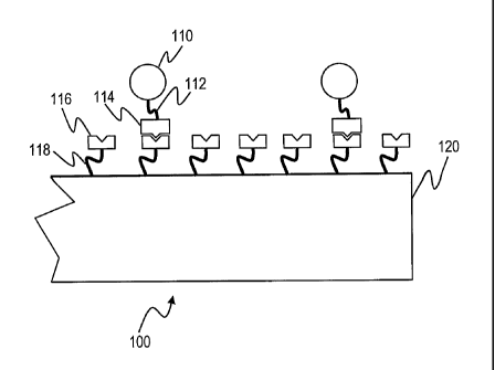
Fig. 1 is a schematic diagram of a biodetection system 100 that utilizes a
probe 116 having affinity
for a target 114. The probe 116 is affixed to a solid substrate 120 by a probe
linker 118. The probe linker
118 will generally comprise a coating that further serves to reduce the
adventitious binding of target
molecules to the substrate 120. The target 114 is connected via a target
linker 112 to a tag 110, which can
be detected by a detector, not shown.
The target 114 can comprise a variety of biomolecules, including nucleic
acids, proteins, starches,
lipids, hormones, and more. Furthermore, the target 1 14 can comprise, as will
be discussed below in
greater detail, whole organisms or oganelles, including bacteria, fungi,
viruses, mycopIasmas, cell fractions
(mitochondria, nuclei), animal or plant cells, and other organisms. In each
case, the probe 116 will match
the target 114, and itself can comprise nucleic acids (both for hybridization
and as aptamers), proteins,
carbohydrates, and can also include whole organisms and organelles as
described above. Indeed, in most
cases, wherever one has a target-probe pair, the constituents can generally be
switched so that the target acts
as a probe, and the probe as a target, on the basis of their affinity for each
other.
In operation, the target 114, which is connected to the tag 110, is introduced
into solution that is in
contact with the probe 116. Because of the molecular affinity of the probe 116
for the target 114, the target
114 binds to the probe 116. Because the tag 110 is attached to the target 114,
the presence of the tag 110 in
proximity to the surface of the substrate 120 indicates the presence of the
target 114. By determining the
amount of the tag 110, the amount of the target 114 can be estimated.
Alternatively, the tag 110, instead of being bound directly to the target 114,
can be attached via a
linker to a second molecule with affinity for the target 114. After incubation
with the probe 116 and the
target 114, a "sandwich" is formed in which the target 1 14 associates with
both the probe 116 and the tag
110.
CA 02532414 2006-01-12
WO 2005/027714
PCT/US2004/022025
14
One of the difficulties of the systems according to Fig. 1 is the time that it
takes for the incubation
of the target 114 and the probe 116 to come to dynamic completion. Consider,
for example, a common
microplate laboratory format in which different probes are placed in a grid of
wells arranged in an eight
column by twelve row well format (as will be described in greater detail
below). The plate well layout is
defined by industry standards and the wells are typically on the order of 9 mm
in diameter. The binding of
the target to the probe requires the two species to be in close proximity
measured on a scale of Angstroms.
In a typical microplate assay diffusion and sometimes convection are utilized
to increase the probability that
the two species come in close proximity to complex at the surface. This
strategy generates significant
signal, at hours long incubation, with typical conventional detection
methodologies at pg/ml concentrations
of a 50 kd model protein. However at sub or low pg/ml concentrations, the
signal generation is limited by
the mass transport of analyte to surface, so that unreasonable reaction times
measured in days are required
for the assay to reach completion.
Furthermore, transport of target 114 to probe 116 is further exacerbated in a
micrometer scale
array of probes (i.e. microarray format). Fig. 2A, a schematic diagram of a
biodetection system taking
place in which different probes 116 are placed in an array 140 of locations
130 on a substrate 120. Each
location 130 is typically on the order of 50 microns to 500 microns in
diameter, and with an array
comprising ten to tens of thousands of locations 130, a typical side-to-side
dimension for the array 140 can
be millimeters or even centimeters. The binding of the target 114 to the probe
116 requires that the two
species be in close proximity measured in Angstroms. Given that the passive
diffusion of large biological
macromolecules is low (e.g. measured in nanometers per second)), the lateral
movement of the target 114 to
the probe 116 can take on the order of tens of hours, unless active assistance
is provided.
Even with assisted movement of the molecules laterally, the vertical scale of
the incubation can
frustrate the target 114 to probe 116 binding. Consider Fig. 2B, a side-view
through the array 140 of Fig.
2A. A cover 111 comprises the top of the incubation cell, and if the target
114 is near the top of the
incubation chamber (delimited by the substrate 120 and the cover 111), the
vertical dimension is still large
by molecular standards. Consider that the smallest vertical thickness used in
conventional incubations is
typically about 50 microns. Given that the target 111 and the probe 116 need
to be within a few Angstroms,
in general, in order to bind to one another, the vertical scale is 10,000
times this size. In the best of cases,
the target 114 would be limited in its movement to a very small volume in the
vicinity of the immobilized
probe 116 to increase its apparent concentration.
A prior art embodiment of a means to overcome this problem is provided in Fig.
3, a perspective
diagram of an electrophoretically-enhanced incubation system. In this case,
the different probes 116 are
affixed directly onto electrically conductive electrodes 150. These electrodes
150 are independently
voltage-biased relative to a reference electrode 140 so as to cause a current
within the incubation chamber,
in which target 114 molecules migrate to the electrode 150. Consider, for
example, that electrode 150 A is
initially voltage biased to attract the target 114. Because of the immediate
proximity of the target 114 and
the immobilized probe 116 at the electrode 150, the binding between the two
species occurs very rapidly ¨
on the order of seconds to tens of seconds. The voltage on the electrode 150 A
is then made neutral or
opposite to its previous bias, and the electrode 150 B is then biased. In this
case, the target 114 molecules
CA 02532414 2015-09-28
CA2532414
would migrate to the second electrode 150 B so as to allow the interaction of
the target 114 with the probe
immobilized in the second location.
This embodiment has been extensively used by Nanogen (San Diego, CA), and the
prior art teachings are
specified in a series of patents, including U.S. Patent #5,849,486 and U.S.
Patent #6,017,696. There are a number of
5 limitations of this embodiment, however. For example, the area covered by
the probe 116 and the respective
electrode 150 must be exactly coincident. In general, this means that the
probes 116 are immobilized sequentially
using movement of the probes 116 analogous to the movement of the target 114
during the incubation. Furthermore,
each probe 116 electrode 150 must establish its own electrical connection to a
power controller, which requires both
sophisticated manufacturing and power control.
10 Arrangement of Components
Some embodiments of the present invention comprise the application of
electrophoretic forces on the target
114 wherein the electrodes involved in such forces are not necessarily
coincident with the locations on which the
probe 116 is attached. The application of electrophoretic force can be
according to a number of embodiments, of
which two are presented for discussion purposes: firstly, in which the
electrodes do not underlie the probe locations
15 116 whatsoever, and wherein the electrophoretic forces are primarily
lateral to the surface of the substrate 120, and
secondly, in which a single electrode underlies a plurality of probe 116
locations. It should be noted that the
structural arrangement of the probe locations and the electrodes giving rise
to the electrophoretic forces will be first
considered, along with various components optimized for use with the present
invention, and thereafter the operation
of the various components in concert will be described. It should also be
noted that dielectrophoresis rather than
electrophoresis can be used to move targets (or tags that are attached to
targets) that are large and electrostatically
polarizable. These methods generally require the use of electrodes that are
shaped either in two or three dimensions
so as to create electrical or electrophoretic fields that are non-uniform. A
description of the use of these
dielectrophoretic electrodes is presented in G. H. Markx and R. Pethig,
Dielectrophoretic Separation of Cells:
Continuous Separation. Biotechnol. Bioeng. 45, 337-343 (1995) and G. H. Markx,
Y. Huang, X.-F. Zhou and R.
Pethig, Dielectrophoretic characterization and separation of micro-organisms,
Microbiology, 140, 585-591 (1994).
Arrangement Involving a Single Electrode Underlying Multiple Probe Locations
Fig. 4A is a perspective diagram of a biodetection cell wherein a single probe
electrode 200 underlies
multiple probe locations 170 which are placed into an array 180. The walls of
the cell are not placed in the diagram,
and will generally comprise gasket material to form a water tight seal. A
reference electrode 190 is physically
placed preferably above the probe electrode 200 and of roughly similar size to
the probe electrode 200, so that the
electric field between the two electrodes is substantially uniform. However,
the reference electrode 200 may have
various shapes and positions that allow for similar or even lesser uniformity.
In general, the electrodes are roughly
parallel to one another, so that the electrophoretic fields that are generated
are roughly perpendicular to the surface
of the probe electrode 200, and give rise to even deposition of the targets
onto the probe locations 170.
CA 02532414 2006-01-12
WO 2005/027714
PCT/US2004/022025
16
This arrangement of the probe electrode 200 and the probe locations 170 allow
for standard
methods of placement of probes on the electrode surface using contact or non-
contact (e.g. pin or
piezoelectric) spotters. Furthermore, the association of the target 114 with
the probe 116 can be performed
in parallel with all of the different probe locations 170, rather than
serially as performed with the prior art.
Arrangement Involving Electrodes Not Underlying Probe Locations
An alternative arrangement is shown in Fig. 4B, a perspective diagram of a
biodetection cell
wherein the electrodes do not underlie the probe locations 170. In this case,
the probes 116 are placed in
probe locations 170 arranged in an array 180. A first electrode 210 and a
second electrode 220 are lateral to
the array 180, and sit underneath an array of partial reference electrodes
195, labeled in this figure P, Q, and
R. The number and type of partial reference electrodes 195 can be varied, and
the goal of the placement of
the first electrode 210, the second electrode 220, and the partial reference
electrodes 195, is to manage the
strength and topology of the electric fields by adjusting the relative
voltages of the electrodes. For instance,
placing the second electrode 220 and the partial reference electrodes 195 P, Q
and R at a negative bias, and
the first electrode 210 at a relatively positive bias will cause a largely
horizontal electric field across the
surface of the array 180. The need for the multiple partial reference
electrodes 195 is due to the "shorting"
of the electric field that would occur with a large, continuous electrode,
making it difficult to maintain an
electric field across a larger electrode.
Fig. 5 is a diagram of electric field strengths from a first electrode 210, a
second electrode 220, and
a set of partial reference electrodes 195. The second electrode 220 and the
partial electrodes 195 have a
negative bias, and the first electrode 210 has a relatively positive bias. As
can be seen, the vertical
component of the electric field at the location of the array 180 is relatively
constant with a downwards
component. By adjusting the relative strengths of the voltage bias at the
different electrodes, a variety of
different electric field topologies can be arranged for purposes that will be
described below.
Electrophoretic Tags
Most biological molecules have associated electrostatic charge, which can be
adjusted by the pH of
the solution in which the molecules are maintained. For nucleic acids, the
charge is generally negative and
determined by the phosphate backbone, and is furthermore directly related to
the length of the nucleic acid.
For the purposes of the present invention, this has certain disadvantages,
since the size of the target 114
molecules can vary. Consider an application in which RNA molecules associated
with different genes will
be measured. In such case, the length of RNA associated with each gene will
vary according to the length
of the gene. Furthermore, RNA from higher organisms is poly-adenylated, and
the length of the "polyA"
tail varies from RNA to RNA. This means that it is difficult to provide a
relatively constant force across all
of the different RNAs, or even across RNAs associated with the same gene.
One method of overcoming this difficulty is to place an "electrophoretic tag"
on each molecule.
The electrostatic charge of this tag will be large compared with the charge of
the polyA tail variation, and
furthermore can be substantial even with regards to the overall charge of the
RNA molecules. In this case,
the variations of charge within RNAs associated with a particular gene due to
polyA tails will be
fractionally insignificant, and the charge differences between RNAs associated
with different genes will be
CA 02532414 2015-09-28
. .
CA2532414
17
fractionally small, even if the RNAs are of significantly different size, as
long as the charge of the electrophoretic
tag is large enough.
Fig. 6 is a schematic diagram of an electrophoretic tag 270 in a sandwich
configuration. The
electrophoretic tag 270 is generally comprised of three functional components
(or fewer components, of which one
or more components can comprise multiple functions). A tag binding component
272 binds the tag 270 to the target
114 through a means that can be either specific to the specific target 114
(e.g. a specific antibody or aptamer), or
which can be common to a large number of targets 114 (e.g. polyT, which will
bind to polyA regions of mRNAs).
An indicator component 290 is detectable by a detector. An electrostatic
component 280 comprises a charged
material, wherein the charge is large and consistent from tag to tag. While
the magnitude of the electrostatic charge
of the electrostatic component 280 can be broad, it is preferable for the
charge to be at least 1,000 net charges, and
even more preferable for the charge to be at least 5,000 net charges, and even
more preferable for the charge to be at
least 10,000 net charges. Furthermore, it is preferable for the charge on the
electrophoretic tag 270 to be of the same
polarity as the charge on the target 114. For example, for nucleic acid
targets 114, it is preferable for the
electrostatic component 280 to be negatively charged.
It should be noted that at certain times, it can be convenient to
independently form an association between
the electrophoretic tag 270 and the target 114. That is, instead of
associating the target 114 with the probe 116, and
then associating the tag 270 with the target 114, the tag 270 and the target
114 are first associated, where the
associated component is called a tagged target 275.
The structure of the electrophoretic tags 270 can be quite varied. Figs. 11A
through F are schematic
diagrams of electrophoretic tags 170, showing differing arrangements of
components to provide functionality within
the scope of the present invention.
Fig. 7A is a schematic diagram of an electrophoretic tag comprised of cross-
linked DNA 281 as the
electrostatic component 280 and fluorescent dyes 291 as the indicator
component 290. The DNA is best largely
double-stranded so that it interferes less with nucleic acid targets 114 and
probes 116, and is conveniently comprised
of regions of double stranded DNA with single-stranded tails that interact
with one another. Furthermore, it is
preferable for the interacting regions to be chemically bonded to provide
integrity to the tag 270 under a variety of
different physical and chemical conditions. An example of this form of
electrophoretic tag 270 is 3DNA
(Genisphere, Hatfield, PA), which is a dendromeric, cross-linked DNA structure
which can be bound to both
fluorescent dyes as well as to a binding component 272. The binding component
272 is conveniently an antibody
with specificity against the target 114, an avidin molecule with specificity
to a biotin moiety attached to the target
114 (or conversely, a biotin moiety with specificity against an avidin
molecule attached to the target 114), an
aptamer selected with specificity to a target, a nucleic acid complementary to
a nucleic acid target 114, or other
specific binding components. It should be noted that for use with messenger
RNA targets, the binding component
272 is conveniently a polyT single-stranded DNA oligomer, which will bind to
the polyA tails of the RNA, or
alternatively a polyT Locked Nucleic Acid (Exiqon, of Vedbaek, Denmark) which
has higher affinity for polyA than
the unmodified polyT.
It should be noted that in many cases, the binding energy between the binding
component 272 and the
CA 02532414 2015-09-28
= CA2532414
18
target 114 will be chosen to be greater than that of the binding energy
between the target 114 and the probe 116.
This can be arranged by either making the binding of the target 114 to the
probe 116 weaker, or more preferably,
making the binding of the binding component 272 to the target 114 stronger.
One method to ensure this is to create
covalent links between the target 114 and the binding component 272. This can
entail, for example, the
incorporation of BrdU into the polyT linker of the binding component 272,
which can be photo-activated to cause
covalent links. In the case of proteins, if the binding component 272 is
comprised of a protein (e.g. an antibody), the
protein can be modified with photo-activatable cross-linking reagents such as
aryl azides (e.g. phenylazide,
hydroxyphenylazide, and nitrophenylazide) and after the target 114 is allowed
to associate with the binding
component 272, light can be used to stimulate cross-linking. The unreacted
cross-linking reagent can then be
consumed using a deactivation reagent, which in the case of aryl azides can
include reducing agents such as thiol-
containing reagents.
While in most cases, the binding energy being discriminated is that between
the probe 116 and the target
114, the discrimination may also take place regarding the binding energy
between the target 114 and the tag binding
component 272. Consider, for example, an antibody sandwich assay, in which
both the probe 116 and the tag
binding component 272 comprise antibodies or parts of antibodies. In that
case, it is equally useful for the weaker
antibody-ligand binding energy ¨ that is, the binding energy that is being
discriminated in the assay ¨ to be with
either antibody. This simplifies the design of such an assay, inasmuch as it
is unnecessary to determine which of the
antibody components to be used in the sandwich assay has a stronger affinity
for the target 114.
This ability to utilize both target 114-probe 116 binding energy as well as
target 114-tag binding component 272
is equally applicable to nucleic acids as well. Thus, the methods of the
present invention will be effective even if the
target 114-tag binding component 272 association is weaker than that of the
target 114 to the probe 116.
Furthermore, this method still applies even if the association between the
target 114 and the tag binding
component is not a specific one-to-one association. Consider, for example, the
case where the tag binding
component 272 comprises a fixed length polyT oligonucleotide, which may be
comprised of Locked Nucleic Acid
nucleotides, which associates with the polyadenylated "tails" of messenger
RNA. The specific association of probes
116 with their targets 114 can provide the spatial specificity of binding of
the targets 114 ¨ that is, where in the
array 180 that the target 114 will bind ¨ whereas the binding energy between
the target 114 and the tag binding
component 272 can provide a consistent binding energy that can be
discriminated by the system.
Covalent cross-linking may occur between both target 114 and probe 116, as
well as between target 114
and tag binding component 272, so as to make a continuously covalent linkage
between the substrate and the
indicator component 290. That is, given the incorporation of proper
activatable cross-linking components into the
probe 116 (see above for a discussion of activatable cross-linking reagents),
after the reaction between the target 114
and the probe 116, activation of the cross-linking moiety bound to the probe
116 can be performed, such that
covalent cross-links between the probe 116 and the target 114 are formed. Such
reaction can occur as well between
the target 114 and the tag binding component 272, as described above. In such
cases, the binding energy holding the
indicator component 290 to the substrate is very large, so that specific
binding can be easily distinguished by its
large binding force.
CA 02532414 2006-01-12
WO 2005/027714
PCT/US2004/022025
19
Fig. 7B is a schematic diagram of an electrophoretic tag comprised of an ionic
polymer 282 as the
electrostatic component 280 and up-converting phosphors 292 as the indicator
component 290. The ionic
polymer can be conveniently linear or branched polyanion, with the ionic
groups comprising either
carboxyl groups (if the pH of the buffer at which the tag 270 is to be used is
near or above the pK of the
carboxyl group), or can also be a polyphosphate, polysulfate (e.g. polyvinyl
sulfonate, polystyrene
sulfonate, sulfated starches, or dextran sulfonate) or other polymer
containing an inorganic acid moiety,
which can comprise phosphates, quaternary amines, tertiary amines, secondary
amines, primary amines,
sulfates, nitrates, and carboxylates. These ionic polymers can be created via
de novo synthesis from
monomeric reagents, or can alternatively be generated by modifications of well-
characterized non-ionic or
weakly-ionic polymers such as polyvinyl alcohol or various starches. It should
be noted that the highly
ionic polymers will be highly attracted to highly ionic species of the
opposite polarity, and that therefore the
electrostatic component 280 needs to be tested to check for non-specific
binding to the substrate 120 or
other species in the analyte solution that can give rise to high backgrounds
in the detection assays.
Up-converting phosphors 292 are particles that convert lower frequency light
into higher
frequency light (see Orasure Technologies, Inc. of Bethlehem, PA), and are
convenient to use due to the
few natural compounds having this property, leading to generally low
background in detection assays.
Fig. 7C is a schematic diagram of an electrophoretic tag comprised of an ionic
polymer 282 as the
electrostatic component 280 and a direct visualization particle 293 as the
indicator component 290. The
particle can be metallic (e.g. gold), ceramic, colored glass, or other opaque
or largely opaque material and is
conveniently at least 250 nanometers, and more preferably at least 500
nanometers, so that it is visible via
light microscopy. The ionic polymer 282 can be comprised of the same materials
as the ionic polymer 282
of Fig. 7B.
Fig. 7D is a schematic diagram of an electrophoretic tag comprised of an ionic
polymer 282 in
conjunction with a low nonspecific binding polymer 284 as the electrostatic
component 280 and a light
scattering particle 294 as the indicator component 290 of Fig. 6. The ionic
polymer 282 is similar to that
shown in Fig. 7B. If this polymer 282 exhibits high nonspecific binding, it
can be coated with a second
polymer 284, such as a form of polyethylene glycol or polyacrylamide, which
exhibit very low nonspecific
binding. This coating will in general involve covalent bonding between the
ionic polymer 282 and the low
nonspecific binding polymer 284.
The light scattering particle 294 can comprise a variety of materials that
scatter light, including
metals, ceramics and glass. The size of these particles is preferably smaller
than 500 urn, and even more
preferably smaller than 200 nm and even more preferably smaller than 50 urn.
An example of such a light
scattering particle 294 is resonance light scattering particles by Genicon
(San Diego, California).
Fig. 7E is a schematic diagram of an electrophoretic tag comprised of a double-
stranded DNA
molecule 285 as the electrostatic component 280 and a quantum dot 295 as the
indicator component 290. In
this case, the electrostatic component 280 is a linear, rather than a branched
or cross-linked DNA molecule:
The indicator component 290 and the binding component 272 are connected on
either end of the DNA
molecule 285. The structure can be assembled by attaching the binding
component 272 to one end of the
single stranded DNA molecule, and then attaching the indicator component 290
to a complementary single
stranded DNA molecule. As the two complementary single stranded DNA molecules
hybridize with one
CA 02532414 2015-09-28
= CA2532414
another, the desired structure is generated. It should be noted that the
double stranded molecule 285 can be replaced
with a single stranded DNA molecule or with a linear polyionic polymer.
Quantum dots 295 function much in the same way as fluorescent dyes, but with a
considerably larger shift
between the excitation and admission frequencies. This large shift allows the
use of higher efficiency optical filters
5 that reduce the amount of background noise in a detection assay. An
example of quantum dots 295 is the
nanocrystals produced by Quantum Dot Corp. (Hayward, California).
Fig. 7F is a schematic diagram of an electrophoretic tag 270 comprised of a
linker component 274 linking
double-stranded DNA molecule 285 as the electrostatic component 280 and a
quantum dot 295 as the indicator
component 290. The linker component 274 comprises attachment sites for three
components: the binding
10 component 272, the indicator component 290, and the electrostatic
component 280. The linker component 274 will
generally have three different binding groups which allow for selective
binding of each group by the three
components separately. An example of such a linker 274 includes the amino acid
cysteine, which has carboxyl,
amino and thiol components of separable reactivities for synthesis, or serine,
which has carboxyl, amino, and
hydroxyl components. There are a number of functional groups that can be used
on the linker in order to allow it to
15 interact with the components 272, 290 and 280. These functional groups
can comprise, for example, thiols, aryl
azides, alcohols, amines, epoxies, n-hydroxy-succinimde, biotin, avidin, or
other chemically active groups or groups
with high affinities (e.g. avidin and biotin).
It should be understood that in the preceding discussion of an electrophoretic
tag 270, the electrostatic
component 280 and the indicator component 290 from the different examples can
be combined separately to create
20 tags of useful benefit. It is further understood that the electrostatic
components 280 and indicator components 290
discussed are not exhaustive, and any chemical or physical component providing
similar function is within the
present invention. For instance, the indicator component 290 can comprise many
materials, such as (and including
modes of detection discussed above) enzyme indicators, chemiluminescent
indicators, electrochemical (e.g. redox)
indicators, radioactive indicators, and others types that are used in
microarray, ELISA, and other biochemical and
chemical assays, upconverting phosphors, fluorophores, quantum dots, light
scattering particles, light absorbing
particles (e.g. colored particles), or phase contrast particles (i.e. to
confer index of refraction differences that can be
visualized in a phase contrast microscope or by surface plasmon resonance).
Many of these indicators can be used with optical detection means which is
matched to that of the indicator.
Thus, for fluorophores, quantum dots, and upconverting phosphors, paired
excitation illumination (e.g. laser
excitation or broad-spectrum illuminators with bandpass filters) and emission-
specific detectors (e.g. bandpass
filtered) are utilized along with proper imagers (e.g. cameras with or without
magnification optics). Light scattering
particles will often use oblique incident illumination (including standard
darkfield condensers) or evanescent
illumination, or may alternatively use phase contrast optics, since particles
with sufficient difference in refractive
index to give rise to phase optical effects will also give rise to light
scattering. In addition, the phase contrast
particles will also generally be visible in surface plasmon resonance. Phase
microscopy can be used for phase
contrast particles, and light absorbing particles and enzymatic reactions can
be used in both phase contrast
microscopy and brightfield imaging (e.g. with microscopic imaging or other
forms of magnification).
CA 02532414 2015-09-28
=
. = '
CA2532414
21
Chemiluminescence can be detected with proper magnification and detectors
arranged to have the proper receptivity
to the chemiluminescent signal.
It should also be noted that is preferable that there be only a single binding
component 272 for each
electrophoretic tag 270 so that each target molecule 114 is associated with
only a single electrophoretic tag 270.
This can be handled by associating targets 114 with a large numerical excess
of electrostatic tags 270 such that, on
average, most electrophoretic tags 270 will be unassociated with target, and
that most tagged targets 275 will have
only a single target 114.
The amount of charge on the electrophoretic tag 270 should generally be
comparable to or greater than the
charge on the targets 114. For proteins, the charge may not be large, those
nucleic acids in general have
approximately one charge per nucleotide, and the size of the targets can be
hundreds to thousands of nucleotides (in
a small number of cases tens of thousands of nucleotides or more). While
bacteria and other organism targets can
have a large charge, there are also generally a number of places for the tag
270 to bind, and so the sum of many tags
270 will often exceed the charge on the organism surface. In general, it is
preferable for the electrophoretic tag to
have an average absolute net charge of greater than 1000, and even more
preferably greater than 5000, and most
preferably greater than 20000.
It should further be understood that in most applications of the present
invention the use of an
electrophoretic tag 270 is not a requirement. That is, most targets 114
intrinsically comprise an electrostatic charge
that allows the target's 114 movement in electrostatic or electrophoretic
fields, and for which targets 114 the tags do
not require an electrostatic component. Where the term electrophoretic tag 270
is used in this description, a non-
electrophoretic tag can be used in conjunction with the naturally occurring
electrostatic charge on the target 114.
Furthermore, the charge of these molecules can often be adjusted by pH, and it
can be convenient to adjust the pH at
which electrophoresis occurs to alter the electrostatic charge on the target
114.
Comnetitiye Assay Formats
The assay formats described above related primarily to sandwich assay formats.
However, in the case of
very small targets 114, such as hormones or drugs of substance abuse, it is
difficult to bind to find reagents that
allow simultaneous, high-affinity binding of both a probe 116 and a tag
binding component 272. Without two such
binding reagents, the sandwich assay is performed with difficulty.
An alternative is a competitive assay, in which a specific binding probe 116
to the target 114 is
immobilized, as before, on the substrate. Added to the analyte containing the
target 114 is a competitor, which binds
to the probe 116 with similar affinity to that of the target 114, and to which
is covalently bound an indicator 290. In
the absence of target 114 in the analyte, a given amount of the competitor
will bind to the probe 116. However, if
the analyte contains the target 114, the binding of the competitor will be
reduced. Thus, in the competitor assay, the
target 114 is not directly detected, but rather its abundance is evidenced by
the reduced binding of the competitor.
The competitive assay format is used advantageously in the present invention,
given the requirements for
consistent and reproducible binding, which is improved by the reaction
acceleration of the present invention.
Furthermore, because the present invention uses relatively short reactions, as
well as rapid washing, relatively low
affinity probes 116 can be used that would otherwise lead to loss of signal
CA 02532414 2006-01-12
WO 2005/027714
PCT/US2004/022025
22
with conventional washing and detection methods. Note that this latter
advantage accrues not only to
competitive assay formats, but sandwich assay formats, as well.
Attachment of Probes
As mentioned above, the probe 116 is attached to the substrate 120 through a
linker 118. This
linker 118 conveniently comprises a coating with functional groups, wherein
the functional groups permit
the binding of the probes 116. Also, the coating preferably has low non-
specific binding, so that target 114
or indicator 290 in solution that is not specific for the probe 116 does not
bind to the surface. Examples of
such coating material includes Codelink by Amersham and OptiChem by Accelr8,
which comprise
hydrogel-like coatings with both very low non-specific background, as well as
electrical properties.
Alternatively, the coating can comprise a derivatized silane.
Other components
There are a number of other components comprising compete systems according to
the present
invention, including power controllers for establishing the potential
differences between electrodes that will
be cause and control the electrophoretic force on the targets 114,
illuminators to illuminate the indicators
290, detectors to detect the signals generates by illumination of the
indicators 290, and storage controllers
(e.g. controllers and hard disk drives) that store the information from the
detectors and then present it to the
user or compare information from multiple sources or times. Some of these
components are well-known in
the art, such as electrophoresis power supplies (which can be computer
controlled and which can be set to
provide either constant voltage or constant current, and which can be
supplemented with digital or analog
electronic circuitry to provide low to high frequency waveforms as described
elsewhere in this specification
and which can also be used for dielectrophoresis), illuminators (e.g. lasers,
arc lamps, incandescent lamps,
microscope light condensers, and which can involve methods of coupkling the
light into light waveguides),
indicators (as described above and below), detectors (cameras, lenses, filter
sets, image analysis software),
and the like, even as their arrangement and use is novel and to novel effect
in the present invention. Where
the components differ from prior art, they will be discussed both above and
below.
Functional Description of the Present Invention
The present invention can be considered to comprise three steps as shown in
Fig. 8, a schematic
block flow diagram of the steps of the present invention.
In a first step 300, the sample comprising the target 114 is prepared for use
in the assay. The
method of preparation depends upon the type of material being assayed, and can
include the maceration of
solid tissue, or alternatively the lysis of cells if the material to be
assayed is of intracellular origin. Solid
material can be removed from the preparation by centrifugation, filtration or
other means, and if nucleic
acid is the target 114, the nucleic acid can be purified away from the rest of
the starches, lipids, and proteins
of the preparation (indeed, whatever the nature of the target 114, it can be
convenient to remove
components that may interfere with later stages of the analysis). If the
material is nucleic acid, it can be
amplified by means such as polymerase chain reaction (PCR) or rolling circle
amplification or other
amplification methods. Generally, the material should be maintained in a
condition that preserves target
114 reactivity with the probe 116, as well as the reactivity of the
electrophoretic tag 270 with the probe 116.
CA 02532414 2006-01-12
WO 2005/027714
PCT/US2004/022025
23
In general, the least amount of preparation will be used that allows for both
high signal and low
background, due to the cost, time, and artifacts that are generally introduced
via preparation.
In this preparation step, the electrophoretic tag 270 can be reacted with the
target 114 in order to
generate a tagged target 275 as described in Fig. 6. Alternatively, this
reaction can occur later in the
process as described below.
In a second step 310, the tagged target 275 and the probe 116 are reacted. In
the case of nucleic
acids, this can comprise a step of hybridization. In the case of protein
targets 114, this can comprise an
antibody-hapten reaction, a protein-aptamer reaction, or a protein-protein
reaction.
It is a teaching of the present invention to accelerate the reaction between
the tagged target 275 and
the probe 116. If the reaction is incomplete, the amount of target 114 bound
to the probe 116 will be less
than optimal. Additionally, because the rates of reaction for different
targets to different probes 116 are
generally different, and because the amounts of target bound to the probe will
not be linear with time, it is
hard to quantitate the amount of target 114 bound to the probe 116 without the
reaction having gone to
completion.
The means of accelerating the reaction involves the movement of the tagged
target 275 under the
influence of an externally applied force, which can be conveniently an
electrophoretic, dielectrophoretic or
magnetostatic force. For this description, electrophoretic forces will be used
as an example. This force can
be applied either by the placement of an electrode 200 under the positions of
the probe 116, or through the
influence of electrodes 210 and 220 that are placed to the sides of the probe
locations 170, in a manner to be
described below.
In the third step 320, unreacted tagged target 275 is separated from the probe
116 and the tagged
target 275 that remains attached to the probe 116 is detected. Importantly,
conditions are set such that
tagged target 275 that is properly reacted with the probe 116 is not removed,
and that other tagged target
275 that is non-specifically bound to the probe 116 or to the substrate 120 is
removed. It should be
appreciated that with multiple tagged target 275 and probe 116 pairs, the
binding force will be different in
the case of each pair. In order to discriminate specific from non-specifically
bound material, a different
discriminating force will optimally be used for each probe 116. This
methodology is outlined in Fig. 9, a
graph of the amounts of material bound versus the binding energy. Line 340
represents the amount of non-
specifically bound material, and is characterized by a very large amount of
material that is loosely bound, a
variable amount of material bound with the intermediate energy, and some
amount of material which is
bound strongly. It should be noted that the shape of this curve will be
different depending upon the
materials being assayed, and that the arguments made below are not dependent
upon the particular shape of
the curve.
Two targets are shown in the figure: target X is represented by line 344 and
target Y is represented
by line 346. Target X has a lower binding energy with its corresponding probe
116 than the target Y. In a
conventional assay in which a single discriminating wash is used for all
target-probe pairs, the
discriminating energy must be chosen such that it is less than the binding
energy of the least tightly bound
target. This binding energy is represented by dashed line 342. It can be seen,
however, that using a single
discriminating energy results in a background represented by the total of all
nonspecific binding 340 to the
CA 02532414 2006-01-12
WO 2005/027714
PCT/US2004/022025
24
right of the line 342. In the location of target Y, for instance, significant
nonspecifically bound material
with binding energy both less than and greater that of the specifically bound
target Y will be present.
In the present invention, washings corresponding to a number of binding
energies will be used.
These binding energies are represented by dashed lines 350 at forces
represented by lines A, B, C, D, and E,
which are successively applied. For instance, a first "wash" at discriminating
energy A is applied, and
virtually all of the tagged material bound at the location of probe X is
detected. Then, -washing at
discriminating energy B is applied, and the material bound at the location of
probe X is once again
determined. The difference between the material at wash A and wash B is
considered to be specifically
bound material corresponding to target X. After subsequent washings at
discriminating forces C, D, and E,
the amount of target Y is considered to be that material present in wash D and
not present in wash E at the
location of probe Y. Thus, the proper discriminating energy for each target-
probe pair is utilized using a
bracketing pair of discriminating washes. In each case, the nonspecific
background is only that part of line
340 that falls between the pair of discriminating washes specific for that
probe location.
It should be noted that the rupture force is dependant on applied force and
the rate of force applied.
For example, under non-equilibrium conditions, the rate of force applied per
unit of time actually changes
the width of the potential energy landscape effectively, increasing the
integrated energy (force through
applied through a distance) required to rupture the interaction. Another way
of stating this is that rapid
pulling apart does not allow time for the relatively slower unbinding process,
so a large force is required to
rip apart the molecules and that the energy landscape or barrier is
significantly higher at rapid loading over
lower loading rates of force. So depending on force loading rate, there will
be multiple critical rupture
forces. Furthermore, the shape of the loading rate versus critical rupture
force is different for each receptor
ligand interaction, since the intermolecular interactions are different. Thus,
multiple antibody- antigen
interactions and non specific binding can be resolved with dynamic force
analysis ¨that is, by observing the
rupture force plotted against loading rate, overlapping binding energy curves
can be separated depending on
loading rate. Therefore, the shape of the applied voltage curve is very
important to control.
It should be noted that the reaction step 310 and the washing and detection
step 320 can be
performed cyclically multiple times. That is, after the washing and detection
step 320 has removed all of
the target 114 from the probe 116 (or the tag 270 from the target 114),
another cycle of reaction and
washing/detection can take place. This has two primary advantages. Firstly, if
there are a small number of
targets 114 in the analyte, the number of binding events detected will be
small. By repeating the reaction
and washing/detection steps, a larger number of binding events can be counted,
improving the statistics of
the results.
Furthermore, differing voltage dynamics (for example, voltage ramp profiles)
can be utilized in
each cycle of the two steps 310 and 320, in order to distinguish specific from
non-specific binding events
that might be distinguished in only by differing responses to voltage
dynamics. For example, in a first
cycle, the voltage dynamics can involve a step function in which voltages are
changed rapidly, whereas in a
second cycle, the voltage dynamics can involve a slow, ramped increase in
voltage.
It should be noted that in order for the foregoing methods to be used, a means
of real-time
detection of the tagged target 275 to the probe must be available. That is, if
each wash were to take a
considerable amount of time and require many manipulations, only a small
number of different
CA 02532414 2015-09-28
CA2532414
discriminating washes could be used. With a real-time detection method,
however, a large number of discriminating
washes can be implemented, getting better definition of specific versus
nonspecific bound material.
It should be further noted that in the following discussion, the use of
electrophoretic forces can be used in
both accelerating the reaction as well as in providing discrimination between
specific and nonspecifically bound
5
material. It should be understood, however, that in a given application, both
uses of the electrophoretic forces acting
on target-probe complexes, or alternatively, only one or the other of these
uses of electrophoretic forces can be used
to beneficial effect.
The number of discriminating washes used for a given assay can depend on the
specific target-probe pairs
used, but in most cases, the number of washes is preferably less than two
times the total number of targets 114 being
10
detected (with two steps each to "bracket" a particular target 114). It is
also convenient for the spacing of the
discriminating energies not to be evenly spaced, but to be tuned to bracket
individual or groups of target-probe
binding energies. The wash may also be performed as a continuous gradient of
stringency, which can be linear in
stringency versus time, or non-linear, with detection of the target 114 being
performed at intervals, wherein the
number of detections is preferably less than two times the total number of
targets 114 being detected.
15
Because of the natural dissociation constant for each of the target-probe
pairs, which relates to a stochastic
dissociation that is often thermally driven, it is convenient to choose
conditions for discriminating washes in which
this statistical component of dissociation is most attenuated. These
conditions will in the case of nucleic acids, for
example, involve moderate pHs, low temperatures, and higher salt
concentrations. These conditions for proteins
might include ionic strength, pH gradients, hydrophobicity, and solvent
polarity as well.
20
It should be noted that while the present invention teaches the use of
electrophoretic potential for
discriminating washes, one aspect of the present invention relates more
generally to the realtime detection of varying
washing regimes, wherein the washing regimes can comprise a variety of
different physical and chemical conditions
beyond electrophoretic force. These forces can comprise increasing
temperature, magnetic field strength (should the
tagged target comprise a paramagnetic particle), dielectrophoresis (for
particles, bacteria, and other targets and
25
tagged targets), shear fluid flow, ionic strength (either increasing or
decreasing), pH (either increasing or
decreasing), surfactant concentration (either ionic or non-ionic), or
competitor concentration (e.g. if the target 114 is
a protein, to add increasing amounts of that protein so that when the bound
target 114 is released, the competitor
preferably binds to the probe due to its high concentration). In addition,
more than one of these conditions can be
applied either simultaneously or in sequence. While it is generally preferable
for these conditions to be applied with
gradually increasing stringency for the stringency to be increased in a step
function, with rapid discreet increases in
stringency. By monitoring the binding of the target 114 to the probe 116 at
various increased stringencies of any of
these conditions, discrimination of specific form non-specific binding can be
improved.
CA 02532414 2006-01-12
WO 2005/027714
PCT/US2004/022025
26
Function Involving Electrodes Not Underlying Probe Locations
Fig. 10 is a schematic block flow diagram of a system involving electrodes not
underlying probe
locations. In a s'tep 360, a negatively charged target 114 is added to a
reaction cell similar to that shown in
Fig. 4B. For purposes of this discussion, the target 114 will be considered to
be a nucleic acid, and the
probe 116 will be considered to be a complementary nucleic acid sequence,
although in practice, the probe
116 could also comprise proteins, glycoproteins, starches, or other molecules
of interest. In a step 362, the
electrode A will be positively biased relative to electrodes B, P, Q, and R,
attracting the negatively charged
target 114 to that electrode, on which it will collect. In a step 364,
electrode B is positively biased relative
to electrodes A, P. Q and R, so that the target 114 is drawn to the electrode
B, during which transit it is
brought into close proximity with the probes 116 at locations 170 in array
180, so as to facilitate reaction
between the target 114 and the probe 116 can take place. The negative bias on
the electrodes P, Q, and R
maintains electric field vectors with downward pointing components during
movement of the target 114 so
that the target maintains close proximity with the probes 116. Once again, it
should be noted that the
location and the relative voltages on the upper electrodes P, Q, and R can be
adjusted to shape the electric
field vectors in the cell. The magnitude of the electric field vectors upward
and lateral from the positions
170 must be lower than the binding force that binds the specifically bound
targets 114 to their
corresponding probes 116.
In an optional step 366, weakly-adhered nonspecifically-bound material can be
removed from the
array 180 by placing a small net positive bias to electrodes P. Q, and R,
drawing the material away from the
array 180. In a step 370, an event indicator, for example an electrophoretic
tag 270, is added to the cell.
Because of the high concentration of the electrophoretic tag 270, reaction
with the target 114 occurs rapidly.
In addition, reaction of the electrophoretic tag 270 with the target 114 can
be accelerated by electrophoretic
means. In a step 372, the electrode A is positively biased relative to
electrodes B, P, Q, and R, transporting
the electrophoretic tag 270 to the electrode A. In a subsequent step 374, the
electrode B is placed positively
biased relative to electrodes A, P, Q, and R, moving the electrophoretic tag
270 from electrode A to
electrode B, with generally downward pointing electric field vectors, so that
the electrophoretic tags 270 are
in close proximity to the targets 114, with which they react. In a step 376,
the electrode B positive bias is
increased in a generally stepwise fashion as the amount of material bound at
the probe locations 170 is
monitored in order to determine the material that is specifically bound and to
discriminate it from material
that is nonspecifically bound. It should be appreciated that the event
indicator can be a tag without
particular electrophoretic properties, should the target 114 be itself
charged. Furthermore, there may be no
event indicator should the target 114 itself have properties of fluorescence,
light absorption, index
difference with the medium, or other properties such that it is detectable,
rendered the step 370 optional.
It should also be noted that the targets 114 can be made to move back and
forth multiple times
between the electrodes 210 and 220, in each case increasing the amount of
target 114 that binds to the
probes.
Function Involving Electrodes Underlying Probe Locations
Fig. 11A is a schematic block flow diagram of the operation of a cell
involving electrodes
underlying probe locations, and can be best understood in relation to Fig. 4A.
In the step 360, a negatively
CA 02532414 2014-07-17
27
charged target is added to the cell. In a step 382, the electrode D is
positively biased relative to electrode C,
causing the target to migrate onto the electrode where it is in close
proximity to the probe 116 placed on
array locations 170 on the array 180. Because of the close proximity, the
reaction between the target 114
and the probe 116 occurs very rapidly. In a step 370, an event indicator, for
example an electrophoretic tag
270, is added to the cell. In a step 386, electrode D is once again positively
biased relative to electrode C.
Under the influence of the electric field, the electrophoretic tag 270
migrates to electrode C wherein it
reacts with the target 114. In a step. 388, electrode C is set at a positive
biased relative to electrode D.
Electrode C's positive bias is increased in a generally stepwise fashion as
the amount of material bound at
the probe locations 170 is monitored in order to determine the material that
is specifically bound and to
discriminate it from material that is nonspecifically bound.
It should be appreciated that the step 370 and the step 386 can be eliminated
by adding the
electrophoretic tag 270 to the target 114 prior to adding the target 114 to
the cell in the step 360. In this
case, the target 114 is converted to a tagged target 275 prior to the
application of a positive bias on
electrode C in the step 382. The creation of the tagged target 275 can occur
within the cell as shown in Fig.
11B, a schematic flow diagram of the operation of a cell involving electrodes
under the probe locations
using a tagged target 275. In the step 360, the negatively charged target is
added to the cell, and in the step
370, electrophoretic tag 270 is additionally added to the cell. At this point,
a tagged target 275 is generated.
In the step 382, the electrode D is positively biased relative to electrode C
and the tagged target 275 moves
into close proximity with the probes 116 at the target locations 170, where
reaction with the probes 116
occurs. In the step 388, discrimination of specifically bound versus
nonspecifically bound material is
performed as before.
The monitoring of the binding of the target 114 that occurs in the step 388
can be performed for an
average of all of the material that is bound ¨ for example, measuring the
total output of light that is
scattered from a tag that has a light scattering indicator. However, if the
detector is an optical detector, and
the detector is an imaging detector such as a camera or a laser scanner
coupled with a photo multiplier tube,
the binding may be determined for individual targets
114. In this case, the detector will need to store the locations of each
target 114 between sequential
detections, and the strength of binding of each target 114 to each probe 116
can then be determined.
Use of Magnetostatic Forces
It should be noted in the discussions above that magnetostatic forces can be
substituted in certain
cases for electrostatic forces. For the use of magnetostatic forces, however,
the targets 114 must be tagged
with paramagnetic particles, given that for the most part, the biological
molecules or organisms to be
detected are not in themselves magnetic. Examples of such particles include
Estapor particles from Bangs
Laboratories (Fishers, IN), and Dynabeads from Dynal, Inc. (Norway). Thus, the
particles 293 and 295 of
Figs. 7C, E and F would be substituted with paramagnetic particles, which are
preferably less than 1 micron
in diameter, and more preferably less than 250 nm in diameter, and most
preferably less than 100 nm in
diameter; in general, the smaller the particle, the less it interferes with
the diffusion of the target 114
towards the probe 116, and the faster the reaction kinetics. Instead of
electrodes, the placement of
permanent or electromagnets either above or below the probe 116 (in relation
to the substrate 120) than
provides the force the moves the magnetically tagged targets 114 towards or
away from the probe 116. The
CA 02532414 2006-01-12
WO 2005/027714
PCT/US2004/022025
28
magnitude of this force can be adjusted either by changing the distance of the
magnetic field source from
the probe 116 or the placement of shims of differing magnetic permeability, or
in the case of an
electromagnet, adjusting the current through the coils, the physical
distribution of the coils, the presence of
magnetically permeable material in or around the coils, and other such means
as known in the art.
Real-time Detection
As described above, the use of multiple washes of differing discrimination, as
well as the
monitoring of the binding of the target to the probe require the use of real-
time monitoring. This is to be
distinguished from the common conventional situation wherein after the
reaction has proceeded for a
predetermined period of time, the reaction is competed, the washes are
performed, and then the substrates
on which the reaction was performed are then prepared for detection. In many
of the preferred
embodiments of the present invention, an optical means of detection is
employed. In those instances where
the electrodes are opposed to each other (e.g. parallel and opposite), in
order for optical detection to take
place, one or both of the electrodes is preferably optically transparent, in
order for an external optical device
to receive the optical signal that is generated between the two electrodes.
With reference to Fig. 4B, this is easily accommodated, wherein the substrate
on which the array
180 is placed can be transparent. However, it may be preferable for the
detector in that case to be placed
above the electrodes 195P, Q and R, or alternatively in the case of an
arrangement such as Fig. 4A, the
detector will generally be external to the electrodes 190 and 200. In such
cases, the use of optically
transparent electrodes is preferred, for which the preferred material for
these electrodes is indium tin oxide
(ITO). Because ITO is not stable generally to voltages above 2 V, this means
that the potential between the
electrodes in the case of ITO should be preferably maintained below this
potential, as will be described in
more detail below.
A more general discussion of detection will be provided below.
Control of Reaction Acceleration
The acceleration of reaction according to the methods above can be improved by
varying the
electric fields both spatially and temporally so as to improve the reaction of
the probe 116 with the target
114. Fig. 12A is a schematic diagram of three electrodes arranged on two
perpendicular axes within a
reaction cell. Electrode El and electrode E2 are representative of electrodes
195, while electrode E4 is
representative of an electrode 200. That is, the array 180 is placed on top of
the electrode E4. The voltage
potential between the different electrodes will be varied in such a way so as
to improve the reaction rates as
described below. In the discussion below, the use of the terms target 114 and
tagged target 275 are used
roughly interchangeably.
Fig. 12B is a graph of the potential difference between the electrodes E2 and
E4 as they vary with
time, with electrode E4 biased positively to E2. There are three time periods
represented on the graph,
denoted as times Ti, T2 and T3. In the period Ti, the voltage potential is
maintained for a considerable
period, such that the majority of the target 114 is brought into juxtaposition
to the probe 116. Because of
the potential difference, both the probe 116 and the target 114 can be forced
downward onto the substrate
120, wherein the maintained voltage restricts their ability to react with one
another. This will occur when
the probe 116 and the target 114 are of the same polarity of electric charge,
such as in the case of nucleic
acid hybridization, although in other target/probe pairs (e.g. protein-protein
interactions), the charge
CA 02532414 2006-01-12
WO 2005/027714
PCT/US2004/022025
29
polarity can be different in the target 114 and probe 116. Even in such cases,
the target 114 can then be
electrophoresed beyond the probe 116, impeding the reaction between the probe
116 and target 114. In
both cases, it is convenient to have a period, described below, that reverses
or relaxes the effects of the
electrophoresis.
In the period T2, the voltage potential can be removed allowing free movement
of the target 114
and the probe 116, accelerating the rates of reaction. However, during this
period T2, the target 114 is
allowed to diffuse away from the probe 116. Thus, during the period T3, the
voltage potential is once more
applied to maintain the close proximity of the target 114 in the probe 116.
The periods T2 and T3 can be
cyclically repeated, until such time that the majority of the complementary
target 114 and probe 116 are
reacted. The durations of the various periods can be varied depending upon the
topology of the reaction
cell, the characteristics of probes 116 and targets 114, as well as the
various electrostatic charges on the
different components, and the manner in which probe 116 is affixed to the
surface 120. In general, for
larger vertical and lateral dimensions of the cell, period Ti will be larger
to allow for the larger distances
over which the target 114 must be moved.
Fig. 12C is a graph of the potential difference between the electrodes E2 and
E4 as they vary with
time, arranged alternatively to that in Fig. 12B. Again, as in Fig. 12B,
during initial period Ti, the target
114 is allowed to migrate under the influence of the electrophoretic force to
the probe 116. In this case,
during a period T4, the electric field is maintained at a very low level so as
to maintain the juxtaposition of
target 114 to probe 116, but with a lower force than that used in Fig. 12B.
This lower force is used in order
to allow more movement of both the target 114 and the probe 116 so that they
are not topologically
constrained during the reaction. During an optional period T5, the electric
field can be reversed very
mildly, so as to release any target 114 that may have become enmeshed on the
surface 120. The relative
duration of the periods T4 and T5 will depend upon the number of factors,
including the type of surface to
which the probe 116 is attached, the charge of the electrophoretic tag 270,
the binding force between the
target 114 in the probe 116, the physical size of the electrophoretic tag 270,
and other factors. It should also
be noted that the duration of the successive periods T4 or the successive
periods T5 need not be equal and
may change over time.
Fig. 12D is a graph of potential differences between spatially displaced
electrodes, such that the
electric field changes not only magnitude but also in direction. With
reference to fig. 12A, electrode E2 is
nearly vertically displaced (i.e. directly opposed) from the electrode 200 E4,
and the electrode El is both
vertically and laterally displaced from the electrode E4. As can be seen from
the graph, electrode 4 is
alternately biased positively and negatively relative to the vertically-
displaced electrodes El and E2. In
addition, in certain cases the bias is relative to El and in other cases the
bias is relative to E2. This causes
the electric field to vary in polarity, in magnitude, and in direction. This
variation in direction means that
tagged targets 275 that become sterically trapped on the surface 120 will feel
force in varied directions that
can facilitate in releasing them from their entrapment.
This arrangement can be carried out with various topological arrangements.
Fig. 13A is a
schematic diagram with three electrodes 195 displaced in two dimensions over a
single electrode 200.
Electrodes El and E3 are displaced in perpendicular directions from the
electrode E2 which is vertically
displaced from the electrode E4. Fig. 13B is a graph of potential differences
between the electrodes of Fig.
CA 02532414 2006-01-12
WO 2005/027714
PCT/US2004/022025
13A. Electrode E4 is maintained at a roughly constant positive potential. The
other electrodes, however,
cycle between a nearly neutral potential and a negative potential, causing the
electric field to cycle in
direction with relatively constant magnitude.
It should be noted that the topological arrangements of the electrodes El, E2
and E3 will vary with
5 the
shape of the cell. For instance if the cell is between a microscope slide and
a cover slip, the thickness of
the cell can be measured in hundreds of microns, which would cause an electric
field between the electrodes
El and E4 to be nearly horizontal. If the cell is within a microtiter well,
the depth of the cell will be
comparable to that of its width, such that the electric field between
electrodes El and E4 will be more
nearly vertical.
10 Electrochemistry to Improve Electrophoretic Acceleration
The electrophoretic reaction acceleration can be performed in a normal buffer,
using the
electrolysis of the water or the constituent salt ions (e.g. sodium and
chloride) to engage in redox reactions
at the electrodes as required to provide the current for the electrophoresis.
There are a number of
difficulties associated with the use of these buffers, however, for which we
will use sodium chloride as an
15
example. Firstly, if indium tin oxide (ITO) or other redox active materials is
used at one or both electrodes
(e.g. to provide an optically transparent or translucent, conductive
electrode), the redox potentials powering
the electrophoresis need to be less than that at which the electrode will
participate in redox reactions. In the
case of buffers with sodium chloride, for instance, the potential at which
redox reactions occur at high rates
is greater than 2 Volts, at which potential the ITO is unstable.
20
Furthermore, the redox products of sodium chloride electrochemistry include Na
metal which
reacts in water to form the strong base NaOH, and C12, which reacts with water
to form strong oxidizing
reagents. These reagents, being very active, may be deleterious to the targets
114 and tags 270 being
electrophoresed towards the electrodes.
Also, while salt provides conductivity to the electrophoresis, it also
competes with the charged
25
material being moved ¨ the larger the conductance of the buffer, the lower
electrophoretic force that is
encountered by the material. Thus, it is beneficial to limit the conductance
of the buffer. In general, it is
preferable therefore for the conductivity of the buffer to be less than 1
mS/cm, and even more preferable for
the buffer to be less than 100 gS/cm, and even more preferable for the
conductivity of the buffer to be less
than 10 p,S/cm. In many instances, it is important for the ionic strength of
the buffer, however, to be
30
maintained at some reasonable level (e.g. > 10 mM), for example for the
viability of cells or to preserve the
reaction of proteins or nucleic acids (e.g. hybridization), or alternatively
to have a buffer to maintain a pH
range. In these cases, it is convenient to use zwitterionic molecules to
maintain ionic strength or pH.
Specifically, in the case where nucleic acid hybridization is desired, it is
convenient to use histidine buffer
(e.g. see US Patent #6,051,380).
Choosing appropriate redox accelerants
In order to reduce these effects, it is preferable to provide redox agents
that do not suffer from the
problems listed above. An example of such reagents is the
benzoquinone/hydroquinone system. In this
case, hydroquinone is oxidized at the anode to benzoquinone, and benzoquinone
is reduced at the cathode to
hydroquinone. Because the reactions are complementary at the electrodes (i.e.
have reversed potentials),
CA 02532414 2006-01-12
WO 2005/027714
PCT/US2004/022025
31
the only cell potential is due to differences in concentration rather than
differences in standard potential at
the electrodes, and thus the electrophoresis redox reaction occur at
relatively low potentials between the two
electrodes. Furthermore, because the two species are not charged, the redox
agents do not significantly
increase the conductivity of the solution and thus do not compete with the
charged molecules (e.g. DNA) or
material (e.g. bacteria) for transport via electrophoresis.
The redox scheme as described above can operate either with respect to a
closed or open system.
Fig. 14A is a schematic diagram of a closed system for electrophoresis. On an
upper substrate 870 is a
cathode 850, and on a lower substrate 870 is an anode 860. In the region
between the electrodes are two
compounds, an oxidized molecule (OX1) which according to the discussion above
could be benzoquinone,
and a reduced molecule (RED1) which according to the discussion above could be
hydroquinone. At the
cathode 850, OX1 is reduced to RED1, which then moves either by
electrophoresis or by diffusion to the
vicinity of the anode 860. At the anode 860, RED1 is then oxidized to OX1,
which then moves either by
electrophoresis or by diffusion to the vicinity of the cathode 850, where the
cycle can repeat itself.
Depending on the amount of availability of charge carriers (which can be
unrelated electrolyte,
RED1 and/or OX1, or charged molecules or materials to be transported), the
electrophoretic force, and
therefore the rate at which molecules or materials can be transported, can be
limited to the rate of diffusion
of OX1 to the cathode and RED1 to the anode. This rate of diffusion can be
improved significantly be
making the distance between the cathode 850 and the anode 860 small ¨ it is
preferable for this distance to
be less than 2000 microns, even more preferable for this distance to be less
than 1000 microns, and even
more preferable for this distance to be less than 500 microns.
The system of Fig. 14A is closed, in that the system can be closed off from
the environment, and
electrophoresis can be continued indefinitely without replenishing the redox
reagents. Fig. 14B is a
schematic diagram of an open system for electrophoresis. The arrangement of
substrates 870, cathode 850
and anode 860 is the same as that of Fig. 48A. However, in this case, there
are two pairs of reagents which
do not regenerate each other (either directly as in benzoquinone and
hydroquinone, or by mutual quenching
of redox products, as described below). At the cathode 850, an oxidized
molecule OX3 is reduced to the
molecule RED3, while at the anode 860, a reduced molecule RED2 is oxidized to
0X2. The products
RED3 and 0X2 do not react with one another to regenerate the reactants, and so
as soon as 0X3 and RED2
are exhausted, electrophoresis will terminate. Thus, in this open system, in
order to maintain
electrophoresis, the reactants OX3 and RED2 must be continuously replenished,
which is accomplished
generally by maintaining a flow of new reactants in the electrophoresis buffer
into the space between the
electrodes. It should be noted that this flow will also remove any targets 114
to be transported, unless such
targets 114 are somehow immobilized to the cathode 850 or anode 860 by the
time that the buffer exits the
region between the electrodes 850 and 860.
There are numerous redox pairs that can operate within the present invention.
As described above,
benzoquinone and hydroquinone are well suited to this, and are preferably used
in concentrations above 1
mM, more preferably used in concentrations above 10 mM, and most conveniently
used in concentrations
above 30 mM. It should be noted that the use of benzoquinone and hydroquinone
are limited to an extent
by their limited solubility, and so more polar or charged derivatives can be
conveniently used to increase
their solubility, such derivatives including the substitution of the ring
carbons not bonded to carbon with
CA 02532414 2006-01-12
WO 2005/027714
PCT/US2004/022025
32
halogens, nitrates, hydroxyls, thiols, carboxylates, and amines, and other
such moieties. It should be noted
that it is optimal for the system for the resulting redox agents to be
uncharged (except as will be shown
below), so that their distribution is not affected by the system
electrophoresis, and so the substitution with a
positively charged group (e.g. an amine) is balanced by a second substitution
with a negatively charged
group (e.g. a carboxylate), such as in 2-amino, 5-carboxy para-benzoquinone.
In such cases of derivatized
benzoquinones and hydroquinones, the concentrations of the redox reagents can
be conveniently increased.
Other similar redox pairs include ketone/alcohol and aldehyde/alcohol pairs,
whose ketone
carbonyl group can be flanked by alkyl or aryl groups, which groups can also
be derivatized with halogen,
nitrate, hydroxyl, thiol, carboxlate, amino and other groups so as to modify
the charge on the molecule or to
increase its solubility. Another convenient system is that of
dithiothreitol/dithioerythritol and their oxidized
forms (which can be formed by the partial oxidation of solutions of the
reduced forms, for example, by
hydrogen peroxide), or alternatively by alkanes with terminal thiol groups
(e.g. 1,5 dithiobutane). In
general, it is preferable for the two thiols groups to be on the same molecule
(as in dithiothreitol) as
opposed to on separate molecules (e.g. as in beta-mercaptoethanol), so that
the oxidation reaction is a
unimolecular reaction that is relatively less sensitive to concentration
(although the single thiols, such as
beta-mercaptoethanol are acceptable reducing agents for many applications).
It should be noted that the redox pairs above are oxidized and reduced in
pairs of electrons in such
a manner that the charge on both redox pairs is the same, and is preferably
neutral. The requirement that
pairs of electrons be transferred can, however, reduce the rate of the
reaction, and so it can also be
convenient to use pairs in which one electron is transferred in the redox
reaction. Examples of such pairs
include ferrocene/ferrocinium and their derivatives, and
ferrocyanidederricyanide. In such cases, it is
preferable to use pairs in which the reduced product is neutrally charged, and
the oxidized product is
positively charged in those cases where negatively charged molecules or
materials will be transported. The
reason for this is that the oxidized product supplies countercharge to the
transport of the negatively charged
transported molecules, and the reduced product is uncharged, and so does not
compete for transport with the
negatively charged transported molecules.
Another configuration of the system is that where the products of the redox
reactions quench one
another, such as in the following:
Anode: 21- - 2e" 4 12
Cathode: S406-2 + 2e- -4 2S203-2
The products of this reaction spontaneously react with one another according
to 2S203-2 + 12 ¨> S406-2 + 21",
regenerating the starting state. The use of iodide or another halide is
convenient, since the iodide is moved
through electrophoresis towards the anode, and the resulting iodine is
neutrally charged and can move
through osmosis towards the other electrode where it will meet with the
thiosulfate for the regeneration of
the initial system.
In open loop systems without recycling, where the redox pairs do not
regenerate one another
during their respective reactions, the range of redox agents is broader, and
conveniently includes
compounds including glutathione, ascorbate, methyl viologen, phenazine
methosulfate, trolox, and others,
including their redox pairs (such as GSSG for glutathione and dehydroascorbate
for ascorbate, oxidized
methyl viologen for methyl viologen). In this case, it is sometimes convenient
that the charge of the
CA 02532414 2006-01-12
WO 2005/027714
PCT/US2004/022025
33
molecule be such that the reactant be attracted towards the electrode at which
it will participate in redox
reactions (i.e. reactants to be oxidized at the anode should be negatively
charged and reactants to be reduced
at the cathode should be positively charged). This can generally be
accomplished by derivatizing the
molecule with one or more appropriately charged moieties. The main
disadvantage of this is that a
negatively charged redox agent, while increasing the rate of reaction, can
also compete with the negatively
charged transport molecules, such that increasing the amount of redox reactant
can even reduce the overall
transport of the transport molecules. Thus, care needs to be taken through
experimentation to ensure that
negatively charged redox reagents do not have an overall deleterious effect.
It should be noted, however, that small molecules of a redox pair, because of
their high diffusion
rates, are only moderately affected by the electrophoresis, and over the short
distances that generally exist
between the cathode and anode, show a modest gradient over the electrodes
(often only 2-3 fold, and
generally less than 10-fold). In this case, it may be useful to have one or
both redox reagents be neutral or
positively charged. In the case where both agents are positively charged, it
is preferable that the agent that
reacts at the positively charged anode be in larger overall molar
concentrations to compensate for the lower
local concentrations at the anode.
In those cases where microorganisms are being transported in the presence of
redox agents, it is
important to note that some of the redox agents mentioned above can have
toxicity for microorganisms. In
cases where the subsequent growth or monitoring of live organisms is desired,
this can be a significant
problem. For that reason, it is useful either to use low concentrations of the
toxic redox reagent (generally
the oxidizing agent), to limit the duration at which the microorganism is
exposed to the agent, or to use an
agent with lower toxicity, even should that agent have less desirable redox
properties. In addition, bacteria
that have been exposed to a toxic redox agent can be treated after exposure to
a counteracting agent. For
example, should the toxic redox agent be an oxidizing agent, the addition of a
reducing agent such as beta-
mercaptoethanol or dithiothreitol can reduce the effects of the oxidizing
agent.
It should be noted that the one of the goals of the use of the redox agents is
to allow
electrophoresis to occur at a lower potential, both so as to minimize the
production of harmful redox
products (e.g. chlorine products from chloride), and as well so that optical
detection can occur using ITO
electrodes, which can be harmed by high potentials. Thus, the cell potential
of the redox pairs chosen for
the application is preferably under 2 V (the potential at which ITO begins to
be affected), and even more
preferably under 1 V and most preferably under 500 mV, since the range of
potentials between the lowest
potential at which electrophoresis occurs (i.e. 500 mV) and the endpoint (i.e.
2 V) will give some measure
of control over the rates of electrophoresis. Even in those cases where the
standard cell potentials of the
redox agents may be outside of these ranges, the use of differing
concentrations of oxidizing agent and
reducing agent can provide a cell potential that allows for useful operation.
Passivation
Redox products generated at the anode and cathode can be potentially harmful
to the molecules
and materials being transported to these surfaces. For example, many of the
redox reactions generate 1-1+
ions at the anode, which cause a local reduction of pH. This reduction in pH,
if large enough, can disrupt
nucleic acid hybridization, denature proteins, interrupt protein-protein or
protein-nucleic acid interactions,
or kill bacteria. Other redox products that are of potential danger also
include strong bases, and strong
CA 02532414 2006-01-12
WO 2005/027714
PCT/US2004/022025
34
oxidizing or reducing agents. In order to prevent these products from
interfering with the molecules or
materials to be detected at the anode or cathode, it is preferable to have a
passivation layer over the
electrode.
In general, it is convenient for this passivation layer to be such that
proteins and nucleic acids are
not detrimentally affected by the chemical or physical properties of the
passivation layer directly and that
the passivation layer not have a significantly detrimental effect on the redox
reactions that occur at the
electrode. It is preferable that the passivation layer be at least 2
nanometers thick, and more preferable that
the passivation layer be at least 5 nanometers thick, and most preferable that
the passivation layer be at least
25 nanometers thick, so that the interaction of the targets 114 and probes 116
with the products of redox
reactions at the electrodes be reduced. Convenient forms of passivation layers
include polymers comprising
either with polyacrylamide (e.g. Codelink by Amersham) or polyethylene glycol
constituents (e.g.
OptiChem by Accelr8), modified with functional groups to which probes for
detection can be attached.
Inhomogeneity Artifacts
It has been observed that under conditions of 10 mM benzoquinone and 10 mM
hydroquinone, an
indium tin oxide (ITO) electrode separation of 300 microns, and a potential of
greater than 1.5 Volts and
less than the breakdown voltage of the ITO, an inhomogeneity develops either
with soluble (e.g. nucleic
acid coupled with a fluorescent dye) or insoluble (e.g. polystyrene spheres)
markers. The inhomogeneity is
evidenced by areas of concentration and rarefaction, where the areas of
concentration start as roughly
circular spots hundreds of microns across that elongate and condense into a
pattern of cells, in which the
borders are areas of concentration, and the central regions of the cells are
areas of rarefaction. Fig. 15 is a
top-view schematic of an approximately 1 cm diameter region in which such
cells have formed. In general,
this inhomogeneity can be an impediment to the use of accelerated transport
via electrophoresis.
There are a number of methods of reducing this inhomogeneity. In a first
reduction method, the
strength of the electrophoretic force can be reduced, either by decreasing the
voltage, or by increasing the
conductivity of the solution. For example, in a solution of 10 mM benzoquinone
and 10 mM hydroquinone
and very low conductivity (e.g. < 100 S/cm), the cells do not appear very
strongly below 1.4 volts. In a
second reduction method, periods of strong electrophoretic force can be
interspersed with periods of lesser
or no electrophoretic force, wherein the amount of lesser electrophoretic
force is preferably less than 50%
of the maximal force, and more preferably less than 25% of the maximal force,
and is most preferably less
than 10% of the maximal force. In general, the period of strong
electrophoretic force should be less than
that at which the cells first form, and such periods are preferably no more
than 5 seconds, and more
preferably no more than 2 seconds, and most preferably no more than 1 second.
The periods without
electrophoretic force are conveniently substantial enough to allow diffusion
of ions to distances large
compared with the vertical size of the cells (i.e. the distance between the
electrodes), and are preferably
more than 100 milliseconds, and more preferably more than 300 milliseconds,
and most preferably more
than 1 second. In a third reduction method, it is convenient to allow liquid
flow to break up the cells, such
as through the use of temperature convection aided by unequal heating of the
walls of the chamber 805, or
through movement of fluid through the chamber 805.
It should be noted that while ITO or other transparent electrode material is
preferable for real-time
monitoring via visible indicators, this does not mean that both the cathode
and the anode need to be
CA 02532414 2006-01-12
WO 2005/027714
PCT/US2004/022025
comprised of ITO. In other instances, it can be preferable for one of the
electrodes to be transparent,
allowing observation into the reaction cell, while the other electrode to be a
relatively non-reactive, opaque
electrode, such as gold or a refractory metal, such as platinum, palladium, or
iridium which are stable in
electrophoresis. In these cases, the resistance in the metallic electrode will
be very small, which can reduce
5 the inhomogeneity effects above, and furthermore, the potential on the
metallic electrode may not have the
same deleterious effect as on the ITO electrode (e.g. with a Pt electrode),
allowing higher potential to be
used in the cell.
Alternatively, both electrodes can be opaque, with one electrode being coated
with gold. In this
case, the detection can be made optically via surface plasmon resonance.
10 Combination of Mixing and Electrophoretic Reaction Acceleration
Given that the electrode 200 is small relative to the lateral dimensions of
the cell, application of
force towards the electrode 200 will result in relatively even distribution of
the tagged target 275 on the
electrode. If the specific location 170 is small relative to the size of the
electrode 200, this will result in
only a small fraction of the tagged target 275 being bound to the probe 116.
It is therefore advantageous to
15 combine the step of mixing with or interspersed with the application of
the forces towards the electrode
200. This is depicted in Fig. 16A, a schematic block diagram of a reaction
involving both vertical forces
and horizontal forces so as to accelerate the reaction of a tagged target 275
with the probe 116. The
methods of providing mixing, such as horizontal forces, will be discussed in
greater detail below, but can be
considered to include physical mixing of the medium in the cell (e.g. through
the use of a physical stirring
20 mechanism, pumps, electroosmotic flow, surface wave acoustics, and other
means), the use of horizontal
electrophoretic forces on the targets 114, the use of magnetic forces on the
targets 114, and other
convenient means. Those forces comprising bulk flow of the solution (e.g.
electroosmosis, stirring, pumps,
and surface wave acoustics) are particularly easy to implement. The vertical
forces can comprise
electrophoresis, dielectrophoresis, filtration, magnetic field attraction and
other such forces as will bring the
25 tagged target 275 (or a suitable target 114 that is not tagged) into
proximity with the probe 116.
It should be noted that the use of "vertical" and "horizontal" is used in
relation to the surface of the
electrodes, and is not related to gravity, up/down or other coordinate
schemes. Given the orientation of the
diagrams, horizontal can be understood in this context to be parallel to the
electrode (or more generally, the
surface on which the probe resides), while vertical can be understood in this
context to be perpendicular to
30 the electrode.
For example purposes, the target 114 is a single stranded DNA 470, and the
tagged target 275
additionally comprises an electrophoretic tag 270. The probe 116 comprises a
complementary single
stranded DNA probe 480, which is attached to the substrate 120. Vertical
forces will tend to move the
tagged target 275 vertically towards the probe 480, whereas the horizontal
forces will allow the tagged
35 target 275 to interact with probe 480 at various locations 170 within
the array 190.
Fig. 16B is a graph of the electrical potential causing movement of the tagged
target 275 vertically,
in time relation to the horizontal forces causing mixing of the tagged target
275. For purposes of this graph,
a positive horizontal force is considered to be in a constant arbitrary
direction along the substrate 120.
Furthermore, a positive vertical force is considered to be in a direction that
encourages the movement of the
tagged target 275 towards the probe 480. As can be seen from the figure, the
horizontal force is relatively
CA 02532414 2015-09-28
CA2532414
=
36
constant. However, the vertical force varies in time, and is sometimes
approximately neutral and at other times very
strong. The vertical force is released periodically in order to allow the
tagged target 275, which can become
enmeshed on the substrate 120 during the application of the vertical force, to
move laterally. The vertical force is
applied initially for a long duration T7 in order to bring the tagged target
275 near to the probe 480. Once the target
is in close proximity to the surface of the substrate 120, subsequent
applications of vertical force can be either of
shorter duration, or of lower magnitude, or both.
Consider, for example, a horizontal force that is sufficient in magnitude and
in duration such that during the
course of the reaction, the tagged target 275 moves approximately the width of
a location 170. In such case, the
location 170 will encounter approximately twice the tagged target 275 than it
would without the application of
horizontal forces, assuming minimal diffusion.
The horizontal forces may also switch direction, so that the target 275 moves
back and forth over the probe
116. In such case, the target 275 will have multiple possibilities of
interacting with the probe, and will thereby
increase its binding. Also, if the probe is attached through a hydrogel
coating, some probe 116 may be sterically
hindered from interacting with the target 275 if the target is moving from one
or another direction, and it can be
advantageous for the target 275 to move back and forth across the probe so as
to provide different movements of the
target 275. Also, in order to increase the amount of binding, the rate of
horizontal movement can be decreased, or
the rate of vertical movement increased.
Control of Mixed Vertical/Horizontal Reaction Forces
Fig. 17A is a schematic block diagram of the means of controlling the
horizontal and vertical forces. The
electrode 200 lies on the substrate 120 and is surrounded by a horizontal
force applicator 520. Different means of
applying horizontal force will be described in detail below. The applicator
520 is connected to a controller 510,
which in turn receives input from a detector 500. The controller controls both
the magnitude of horizontal force
applied by the applicator 520, as well is the vertical force that is directed
by the electrodes 195 and 200. The
detector 500 monitors tagged target 275 that is in close proximity to the
electrode 200 in real time. That is, tagged
target 275 that is within tens or hundreds of nanometers of the electrode 200
is detected, whereas other tagged target
275 at a further distance from the electrode, is not. The means by which this
real-time monitoring is performed by
the detector 500 will be discussed in greater detail below.
Fig. I7B is a schematic block flow diagram of the operation of the system of
Fig. 17A. In the step 530, the
controller 510 causes a vertical force to be exerted between the electrodes
195 and 200 such that the tagged target
275 moves towards the electrode 200. In a step 532, input from the detector
500 is used by the controller 510 to
determine whether an increasing amount of tagged target 275 is being detected
that is juxtaposed to the electrode
200. If increasing target is being detected, continued vertical forces are
applied in the step 530. If no new tagged
target 275 is detected by the detector 500, the controller relaxes the
vertical force in a step 534. In a step 536, the
horizontal force or flow is either maintained or activated at this point.
Because of the relaxation of vertical force in
the step 534, tagged target 275 diffusing from the surface of the electrode
200 comes under the influence of the
horizontal force or flow and moves laterally along the surface of the
electrode 200. In a step 538, the detector 500
monitors the amount of tagged target 275 juxtaposed to the surface of the
electrode 200. If the amount of target is
CA 02532414 2015-09-28
CA2532414
37
still decreasing, the relaxation of the vertical force in the step 534 is
maintained. Alternatively, a fixed amount of
time can be allowed to elapse. Once the amount of target detected by the
detector 500 is relatively steady, or the
fixed amount of time elapses, the cycle is repeated beginning with the step
530.
Horizontal Forces and Flows
There are a number of different horizontal forces and flows that may be used
herein. Among these include
electrophoretic forces, electroosmosis, acoustic waves, mechanical stirring,
and fluid pumping. For example, in Fig.
4B, lateral electrodes 210 and 220 can be used to apply horizontal forces to
tagged targets 275. In such case, the
magnitude of the vertical electric field can be adjusted by the potential on
the reference electrodes 195, in relation to
the magnitude of the horizontal electric field from the electrodes 210 and
220.
With respect to acoustic waves, piezoelectric actuators can be placed either
on the substrate 120 or on the
cover 111 in a topological arrangement such that under a high frequency
control signal, surface acoustic waves in
the glass cause mass transport of the fluid in which the tagged target 275 is
suspended. In such case, a convection
current is created within the cell which maintains a constant laminar flow
across the surface of the substrate 120. By
alternating the control of the piezoelectric signals, periods of turbulent
mixing can be alternated with periods of
laminar flow.
Mechanical or electroosmotic pumping can also be used to create laminar flow
across the surface 120.
While mechanical pumping is convenient for larger volumes, electroosmotic
pumping can be used to assist even in
the case of extremely small volumes. In such case, the electroosmotic surfaces
can be incorporated either into the
substrate 120, or more conveniently into the cover 111, since the substrate
120 is often covered by a custom surface
used primarily to bind probe 116 and to reduce the amount of nonspecific
binding, and which may be a less effective
surface for creating electroosmotic forces.
Fig. 18A is a perspective diagram of a mechanical stirring system that can be
used within a microtiter plate
well 550. The microtiter plate well 550 has a round probe electrode 560 on its
bottom surface connected to the
outside of the microtiter well 550 by an electrical trace 558. A reference
electrode 570 is immersed within the
analyte fluid whose height is represented by the dashed line 556. The
reference electrode 570 is mounted on a shaft
552 which has both mechanical and electrical connections to actuators not
shown in the figure.
During operation, the shaft 552 provides not only electrical connections
through which a potential bias can
be placed on the reference electrode 570, but in addition, the shaft 552
causes the reference electrode 570 to rotate.
Because of the viscosity of the analyte fluid, the fluid convects in a
circular motion around the microtiter plate well
550, with roughly equal degrees of movement within each radius from the center
of the well 550. By reversing the
direction of rotation of the shaft 552 in the reference electrode 570,
turbulent flow within the well 550 can be
induced.
It should be noted that due to the symmetry of the situation, and due to the
desire to have roughly equal
amounts of conductive flow for each of the probe locations 170, it can be
preferable for the probe electrode 560 to
have circular symmetry. Fig. 18B is a top view diagram of the probe electrode
560. The electrode 560 is arranged
as an annular ring of conductive material attached to the trace 558. Probe
locations 170 are arranged around the
ring, and are roughly equidistant from the center of the microtiter well 550.
In this arrangement, there is no
CA 02532414 2015-09-28
= CA2532414
38
preference in the electric field or the association of targets 114 to probes
116 based on physical location.
Furthermore, conductive laminar flow induced by the electrode 570 will cause
tagged targets 275 to move in a
circular movement around the electrode 560.
It can alternatively be convenient for the reference electrode 570 not to be
symmetrically placed at the
bottom of the shaft 552, but rather to be asymmetrically disposed. In such
case, the electric field direction will
rotate with the shaft 552, providing the benefits of changing electric field
directions, as described above.
The microtiter plate assays can be run either one at a time, or multiple
assays at a time. Fig. 19A is a
perspective diagram of a microtiter plate 590 with a set of electrodes 570 and
shafts 552. The electrodes 570 and
shafts 552 each fit into single microtiter wells 550 arranged in a grid. The
electrodes 570 and shafts 552 can either
rotate or be in fixed position. Depending on the arrangement, it is convenient
either to have all of the electrodes 570
and shafts 552 be fixed with respect to each other, allowing for parallel
operation in all wells and for simple and
inexpensive construction, or individual electrodes 570 and shafts 552 can be
independently controlled.
Alternatively, instead of a two-dimensional array of shafts 552 and electrodes
570 as shown, there can be a one-
dimensional array, in which a single row of wells on the microtiter plate are
processed at one time.
The microtiter plate 590 can be of unitary construction, or alternatively be
constructed of a top plate and a
bottom plate, in which the top plate is made of plastic and defines the sides
of the wells, whereas the bottom plate is
made of plastic, glass or other substrate that is substantially flat, and
which is coated with a material reducing non-
specific binding and to which probes 116 can bind. In such case, the bottom
plate is adhered to the top plate using
adhesive, preferably after the printing of the array 180 of probe locations
170. For purposes of the present
invention, it is convenient for electrodes to be placed on the bottom plate
prior to the printing of the probes 116 or
the adhering of the bottom plate to the top plate.
Fig. 20A is a top view of the arrangement of well electrodes 598 on a bottom
plate 592. The well
electrodes 598 can be square (as shown), rectangular, ellipsoidal, circular or
annular (as in electrode 560), and are
connected to end pads 594 via traces 558. These traces can be of relatively
constant width, but are preferably
narrower at the locations of the wells (denoted by dotted lines), where the
majority of the electrically conductive
area is preferably that of the well electrodes 598. The electrically-
conductive traces that are not part of the electrode
598 may be covered with a non-conductive coating (e.g. semiconductor
materials, ceramics, oxides, and other
materials), but this is an additional step and cost of manufacture and may not
be always convenient. In addition,
there may be multiple traces per well, such as would be convenient with
electrodes not underlying probe locations.
There is an attachment pad 594 for each electrode 598, to which the electrical
attachment is made. This is
less convenient when the number of wells 550 (and therefore electrodes 598)
becomes very large. Alternatively,
multiple electrodes 598 can be connected to a single pad 593, as shown in Fig.
20B, a top view of the arrangement
of electrically-connected well electrodes 598 on a bottom plate 592. In this
case, there is a single electrode 593 to
which all electrodes 598 are electrically connected. Even if not all
electrodes 598 are in simultaneous use, this
arrangement allows for simple electrical connectivity, and no harm occurs with
the parallel connection with the
unused electrodes 598. The connection of all electrodes 598 within a single
row or column of the array of wells 550,
whereas each row or column is connected to a different attachment pad 594.
CA 02532414 2015-09-28
CA2532414
39
As described above, the bottom plate 592 is adhered to a top plate. If the
bottom plate 592 is smaller than
the top plate, the pads 594 or 593 can be grabbed by an electrical attachment
device from underneath the plate
(access through the top and sides is prevented by the top plate). An
alternative arrangement that succeeds regardless
of the relative sizes of the top plate and the bottom plate 592 is shown in
Fig. 19B, a perspective view of a top plate
591 comprising access ports 597. In this arrangement, the access ports 597
provide side access to connect with the
pads 593 or 594. The access ports 597 are placed according to the locations,
number and sizes of the pads. Access
to multiple pads from a single port 597 may also be employed.
An alternative arrangement is for the bottom plate 592 to be uniformly
conductive, and maintained at a
ground potential. In such case, the electric field within each microtiter well
550 can be independently adjusted by
adjusting the potential on the corresponding electrode 570. In the case where
one electrode 570 is operating at the
time, the use of the uniformly conductive bottom plate 592 is straightforward.
When multiple wells 550 are
simultaneously being operated via a multiplicity of operating electrodes 570,
it is optimal if the electrical
conductivity of the analyte solution in each well is low relative to that of
the bottom plate 592. The electrical
conductivity of the analyte solution can be adjusted by, for example, lowering
the concentration of ions in solution.
Microtiter wells can be used within the present invention without use of
permanent electrodes on the
bottom plates 591. Fig. 21 is a perspective side diagram of an integrated
electrode 600 for microtiter plates. The
integrated electrode 600 comprises three sets of independently modulatable
electrodes: a reference electrode 606, a
first lateral electrode 610 and a second lateral electrode 612. Each of these
electrodes can, in turn, comprise
electrodes that can be independently controlled.
The electrodes 606, 610 and 612 are mounted on a shaft comprising vertical
members 608 and plate 602,
which provide both physical support as well as electrical connections. Input
electrical control is provided through
shafts 604, which comprise both physical and electrical connections as well.
The number of shafts 604 can be as
small as one. The lateral electrodes 610 and 612 correspond roughly to
electrodes 210 and 220 of Fig. 4B, and the
reference electrode corresponded roughly to the electrodes 190. These
electrodes are conveniently comprised of a
relatively unreactive metal with high conductivity, such as gold. It is
preferable for the lateral electrodes 610 and
612 to be relatively thin, and can also taper at their interior edges to
maintain a flat lower surface, allowing electric
fields to be controlled near to the bottom of the electrode 600.
The integrated electrode 600 is placed in a microtiter plate well 550 with the
bottom surface of the lateral
electrodes 610 and 612 placed on to or very near to the bottom of the well
550, with the array 180 of probes 116
sitting between the two lateral electrodes. The electrode 600 performs
similarly to the arrangement of Fig. 4B. As
the conclusion of each assay, the electrode 600 is removed from the well 550
and washed with strong applied
electrical potentials, physical agitation in a solution, and possibly chemical
washes in strong acids, oxidizing
reagents and other cleaning solutions. The electrode 600 may be turned in a
roughly circular or in a back and forth
motion so as
CA 02532414 2006-01-12
WO 2005/027714
PCT/US2004/022025
to mix and/or move the target 114 in accordance with the methods described
above (e.g. see Figs. 33A and
33B).
Acceleration of Signal Generation Using Electrophoretic Manipulation
In some cases, the tagged target requires subsequent exposure to substrate in
order to generate
5
signal that can be detected by a variety of means. For example,
chemiluminescence requires the addition of
substrate to enzyme tag in order to generate chemiluminescent signal.
Electrophoretic forces can be used to
drive enzyme reaction by bringing substrate in close proximity to enzyme and
then upon enzymatic
conversion of substrate to opposite electric charged state can be use to drive
converted substrate away from
enzyme rapidly enabling more rapid conversion of the substrate by the enzyme.
10 Washing-Detection
Overview
In the sections above, numerous references are made to discriminating
specifically bound versus
nonspecifically bound material by increasing the bias on an electrode that
pulls the electrophoretic tag 270
and the attached target 114 away from the probe 116 with increasing amounts of
electrostatic force. This
15
process is described in more detail in Fig. 22, a schematic block flow diagram
of discrimination using
electrophoretic force.
In a step 400, optional chemical washes are used to remove loosely-bound
nonspecifically bound
material. These chemical watches can include low-salt, high pH, low pH, or
other chemical treatments
which lower the binding force between the target 114 and the probe 116.
20 In a
step 402, the chemical washes performed in the step 400 are replaced with a
stability buffer
that tends to increase the binding force between the target 114 and the probe
116. The stability buffer
reduces the chances that the target 114 and the probe 116 will separate
adventitiously. It should be noted
that in the absence of the step 400, the step 402 can also optionally be
eliminated.
In a step 404, the tagged target 275 attached to the probe 116 is visually
monitored. In general,
25 this
will involve either capturing an image of the array 180, or scanning the array
180 in a manner to be
described below. In general, the detection means is matched to the type of
indicator component used in the
electrophoretic tag 270. It is important that the tagged target 275 which is
not associated with the probe 116
is not monitored in this situation. Methods of real-time detection for
discriminating bound from unbound
electrophoretic tag 270 are described above and below. In a step 412, the
visual data that is captured is
30 stored.
In a step 406, the net vertical bias away from the probe 116 is increased in a
manner to be
described below. This increase will generally be incremental in a manner shown
in Fig. 9. In a step 408, it
is determined whether or not the maximum stringency from the electrophoretic
force has been reached. If it
has not been reached, new visual data is captured in the step 404. If the
maximum stringency has been
35
reached, the differences in binding for each electrophoretic stringency is
computed from the differences
between successive captured visual data in a step 410, as described below.
It should be noted that for visual detection, there are a variety of different
illumination schemes
that can be employed. Some of these illumination schemes require specialized
condensers, for use in phase
and other types of microscopy. For use in the detection of scattered light, as
well as with the use of
CA 02532414 2012-05-23
41
fluorescent, quantum dot and up-converting phosphors, and certain other modes
of detection, the use of
other forms of illumination can be used. In many cases, the use of evanescent
wave illumination can be of
particular use, because the light that does not interact with the target 114
or its tag 270 can be oftentimes
prevented from interfering in the detection, and because the only tags 270
that will interact with the light
will be those tags that are proximal to the probes 116 on the surface or the
substrate, The following
discussion will go into detail into the means by which evanescent illumination
can be used in visual
detection of the tagged target.
Evanescent Illumination Detection Using Parallel Beam Illumination
Fig. 23A is a cross-sectional schematic of an embodiment of the present
invention in which a
prism 1140 on the top surface is used to introduce light into the slide
waveguide 1120, The prism 1140
shown in the figure is a triangular parallelopiped, in which one surface is
placed on the top surface 1122 of
the slide 1120, and the acceptance surface 1142 faces roughly in the same
direction as an edge 1123 of the
slide 1120. Roughly parallel light rays 1132, which are preferably nearly
perpendicular to the surface 1142
but which can be non-normal and therefore refracted at the surface 1142, enter
the surface 1142 with little
reflection. These light rays 1132 encounter the bottom surface of the prism
1140, and due to the flatness
and juxtaposition of the bottom surface of the prism and the top surface 1122
of the slide, the light rays
1132 bridge the gap between the prism 1140 and the slide 1120, entering the
slide 1120. The direction of
the light rays 1132 is chosen so that the rays 1132, when encountering the
bottom surface 1124 of the slide
1120, will nearly all reflect off of the surface 1124, impinging at greater
than the critical angle between the
surface 1124 and the medium (generally air) below.
The top surface 1143 of the prism 1140 is chosen so that all of the light rays
1132 that enter the
prism 1140 are captured into the slide 1120, and it is of some convenience
that the angle between the
acceptance surface 1142 and the top =face 1143 of the prism 1140 should be
roughly perpendicular. It
should be noted, however, that if the apex 1145 of the prism were to be
extended far enough along the slide,
that raypaths reflected off of the bottom surface 1124, moving upwards to the
top surface 1122, could
encounter the bottom surface of the prism 1140, resulting in "escape" of the
light from the slide. This
should be avoided by not extending the apex 1145 too far distally along the
slide 1120.
While the parallel rays 1132 are shown to be nearly perpendicular to the
acceptance surface 1142,
and therefore exhibit almost no refraction, '
the light rays
1132 to enter non-perpendicularly to the surface 1142, such that the refracted
ray paths have an appropriate
trajectory, resulting in nearly total internal reflection within the slide.
Fig. 23B is a cross-sectional schematic of a prism 1140 on the top surface of
a slide, in which light
is internally reflected within the prism prior to introduction of the light
into the slide 1120. In many cases,
it is preferential to keep device components roughly perpendicular to one
another in order to aid alignment,
and in this case, the incident light rays 1132 can be nearly perpendicular to
the edge 1123 of the slide 1120
(and therefore parallel to the top surface 1122 of the slide 1120). The
acceptance surface 1142 can be
parallel to the slide edge 1123, so that the rays 1132 are perpendicular to
the surface 1142, thereby limiting
reflection at the surface 1142.
After an internal reflection on the top surface 1143 of the prism 1140, the
light rays 1132 now have
the proper angle into the slide 1120 so as to exhibit total internal
reflection. It should be noted that the
CA 02532414 2015-09-28
= CA2532414
42
angle of the ray paths 1132 after reflection on the surface 1143 of the prism
1140 will be twice that of the slope of
the prism 1140 ¨ therefore, the slope of the top surface 1143 needs to be
reasonably small in order to maintain total
internal reflection of the raypaths 1132 within the slide 1120.
Fig. 24A is a cross-section schematic of the prism arrangement of Fig. 23,
extended so that the disposition
of the distal parallel raypaths 1132 can be seen. Parallel ray paths 1132
enter the prism 1140, and then enter the
slide 1120. Because of the parallel nature of the ray paths 1132, the pattern
of reflections within the parallel walls of
the slide 1120, acting as a waveguide, are maintained along the length of the
slide 1120. If the rays are bounded by
the parallel topmost raypath 1133 and the bottommost raypath 1135, and the top
surface 1122 and bottom surface
1124 are parallel, illuminated sections 1146 will be repeatedly interspersed
with unilluminated sections 1148 along
the length of the slide 1120. This will cause significant differences in
reporter 1110 illumination along the slide
1120. This non-uniformity can be to some extent handled by the use of a wide
beam of illumination, but it will
generally be difficult to modulate beam width so that illumination is
precisely uniform
Evanescent Illumination Detection Using Convergent Beam Illumination
Fig. 24B is the cross-sectional schematic of Fig. 24A, modified by the use of
convergent illumination
instead of collimated illumination. Converging illumination 1131 enters the
prism 1140, during which it is refracted
somewhat at the acceptance surface 1142. It is convenient that the point of
convergence of the ray paths 1131 not be
at the interface between the prism 1140 and the slide 1120, since any
imperfections in the glass or contaminants (e.g.
dust) at the interface could contribute to light scattering. Scattered light
would not necessarily maintain total
internal reflection in the slide 1120, and so the point of convergence is
preferably either before or after the point at
which the light 1131 enters the slide 1120.
Looking at the light in the slide, the trajectories of the topmost raypath
1133 and raypath 1135 can be
observed. As can be seen, there is no repeating nature to the areas of
illumination and non-illumination for the ray
paths 1133 and 1135. Indeed, there is a large range of raypath angles within
the light 1131, so that indeed much of
the top surface 1122 of the slide 1120 is illuminated after only a small
number of internal reflections, and given a
very large number of reflections, the illumination of the top surface 1122
becomes nearly uniform. As before, a
wider beam will generally result in somewhat more uniform illumination in the
case of fewer reflections.
It should be noted that a divergent spread of illumination entering the
acceptance surface 1142 would have
a similar effect to a convergent illumination, resulting in nearly homogeneous
evanescent illumination of the top
surface 1122.
Evanescent Illumination Detection Using Non-Uniform Illumination
While the embodiments of Figs. 23A and B and Fig. 24A and B can be used with
the prism 1140 and/or
associated illumination source being in a fixed location, possibly near the
end of the slide, prism 1140 and/or its
associated illumination source can also move to illuminate different areas of
the slide, particularly wherein the
illumination is intentionally non-uniform.
Fig. 24C is a schematic cross-sectional diagram of a slide illuminator in
which the slide is non-uniformly
illuminated. The prism 1140 sits on the top surface 1122 of the slide 1120,
and accepts parallel rays 1132 from a
collimator 1170. A fiber optic cable 1174 conveys light to the collimator
1170, and light rays diverging from the
CA 02532414 2015-09-28
CA2532414
43
end of the fiber optic cable 1174 are captured by and converged by a lens
1172, producing collimated rays 1132.
As in Fig. 24A, the light rays 1132 enter into the prism 1140, and thence into
the slide 1120, wherein they
then reflect multiply against the top layer 1122 and the bottom layer 1124,
illuminating the top surface 1122 at
regular intervals 1. The length 1 can be computed to be 2*(1/tane, where d is
the thickness of the slide and 0 is the
angle complement of the angle of incidence of the light onto the top or bottom
surface of the slide.
A detector 1160 is positioned over the spot of illumination 1146 on the top
surface 1122 of the slide 1120,
and detects a signal resulting from the evanescent illumination of the
reporters 1110 residing on the top surface
1122. It should be noted that the detector 1160 could also be positioned over
integral multiples of 1 in distance on
the top surface, which is of special convenience should there be topological
constraints on the location of the
detector 1160 relative, for example, to the prism 1140. It should be
understood that the detector technology can
comprise both imaging devices (e.g. CCD or CMOS cameras operating with a
relatively constant light source) and
non-imaging devices (e.g. a photomultiplier tube (PMT) operating in
conjunction with a laser scanner illuminating
the surface through prism or other coupling).
While this arrangement is effective for illuminating material at a particular
position relative to the prism
1140, this arrangement can also be used to illuminate many areas on the top of
the slide 1120. This can be
accomplished, for example, by sliding the prism 1140 and the associated
collimator 1170 in concert over the top
surface of the slide 1120. A movement of the prism 1140 and collimator 1170
would result in a concomitant
movement of the spot of illumination 1146 of an equal amount.
Alternatively, the prism can be kept in a single location, and the collimator
1170 can be translated
horizontally or vertically, maintaining its orientation, such that the point
of entrance of the light ray 1132 into the
prism is altered. This will translate the light ray 1132 laterally within the
slide. Furthermore, rotation of the
collimator 1170 would have a translational effect on the position of the spot
of illumination 1146. There may also
be a combination of more than one of the movements of the collimator 1170,
possibly in concert with movement of
the prism 1140, in order to effect translation of the spot 1146 along the top
surface 1122.
Evanescent Illumination Detection Using To Surface Thin Film Waveguide
Another embodiment of the present invention is to make a very thin waveguide,
rather than using the slide,
which generally has a thickness of a millimeter or larger. This can be
accomplished in a variety of ways. For
example, the slide itself can be constructed as a film, possibly of a flexible
high index plastic material. This may not
be convenient in certain applications, including such cases where the film is
to maintain structural rigidity; the
plastic material is inappropriate for the biological and chemical reactions
used in the detection process, and allowing
the material to bend will potentially allow light to escape when internal
reflection angles become less than the
critical angle.
An alternative embodiment is shown in Fig. 25A, a schematic cross-section of a
high index thin film
waveguide 1180 deposited on a slide substrate by physical vapor deposition
(e.g. sputtering or
CA 02532414 2006-01-12
WO 2005/027714
PCT/US2004/022025
44
evaporation), by chemical vapor deposition, by spin coating, dip coating, or
by other means that provides a
film of roughly uniform thickness. Furthermore, graded index of refraction
thin films can be generated
using sol-gel and ion exchange methods. A review of the methods for producing
such thin waveguides is
provided in "Planar integrated optical methods for examining thin films and
their surface adlayers" by
Plowman, Saavedra and Reichert (Biomaterials (1998) 19, pg. 341-355).
The thin film waveguide 1180 is comprised of a material that has a
substantially higher index of
refraction than the underlying slide 1120. The material is conveniently Ta205,
which is commonly used in
the high-index layers in the production of thin-film interference filters,
although other materials can be
used, such as Ti02, silicon nitride, ion-doped silica, and ion-doped glasses.
The thickness of the waveguide
is generally on the order of a wavelength of the guided light, which in this
case will typically be in the
visible or ultraviolet (UV) range, and can conveniently be on the order of 100-
5000 nm, and is more
preferably 150-2000 nm. Because of the small thickness, only one or a few
modes are transmitted in the
waveguide (i.e. single-mode) as opposed to the multi-modal transmission of
light in a thick waveguide (e.g.
the slide).
Coupling of the incident illumination into the thin film waveguide can be
accomplished in a
number of ways. Fig. 25A is a schematic cross-section of an end-illuminated
thin-film waveguide 1180
integrated with a slide 1120. A fiber optic cable 1174 transmits light along a
single-mode fiber 1175, which
terminates in a coupler 1182. The coupler 1182 can also be seen in Fig. 25B, a
schematic top view of the
coupler 1182 and the slide 1120 of Fig. 25A. Light exiting the fiber 1174
encounters a conditioning lens
1177 that is used to adjust the divergence of the emergent light rays, and may
be either convergent or
divergent. The light is then passed through a cylindrical lens 1178 to
converge the beam in a single
dimension, oriented in such a way that the emerging light lines up roughly
with the waveguide 1180.
Optimally, the focal point is roughly coincident with the edge surface of the
waveguide 1180. The beam so
constrained gains significant admittance into the waveguide 1180.
The coupler 1182 encapsulates the terminus of the fiber optic cable 1174, as
well as the
conditioning lens 1177 and cylindrical lens 1178. A positioning lip 1183 on
the top front of the coupler
1182 is used to position the coupler 1182 onto the slide 1120 with the optics
arranged to couple light into
the waveguide 1180.
It should be noted that the optical arrangement of lenses can be varied within
the teachings of the
present invention. For example, the fiber optic cable can be butt-end
juxtaposed directly to the edge of the
waveguide 1180. Alternatively, the conditioning lens 1177 can be left out, in
part depending on the
placement of the cable 1174. Also, the cylindrical lens 1178 can be omitted,
given a conditioning lens 1177
that converges on the edge of the waveguide.
It should be noted that there can be some leakage of the beam either above the
waveguide 1180 or
into the slide 1120, which for very narrow waveguides can comprise the
majority of the light from the
cylindrical lens 1178, since coupling tends to be inefficient. With leakage
above the waveguide, the
coupler 1182 has an overhang that lies on top of the waveguide 1180, both
helping in aligning the coupler
1182 so that light from the fiber optic cable 1174 enters the waveguide 1180,
and secondly, blocking light
escaping from the coupler 1182 forwards. With leakage into the slide 1120,
small amounts of light that leak
into the slide 1120 will tend to be constrained within the slide 1120 (acting
as a waveguide). Other light
CA 02532414 2006-01-12
WO 2005/027714
PCT/US2004/022025
with a higher angle (so that it doesn't reflect) will first encounter the
bottom surface of the slide 1120,
where it will escape and also not affect the evanescent or other illumination
above the waveguide 1180.
An alternative method of coupling the illumination into the thin film
waveguide 1180 is to place a
grating onto the surface of the waveguide 1180. The principle of operation and
construction of such a
5 grating coupler is provided in Plowman, et al. (reference provided
above). Fig. 25C is a schematic cross-
section of a grating 1181 on the surface of the waveguide 1180, with incident
illumination thereby captured
into the waveguide 1180. The grating is positioned on the top surface of the
thin-film waveguide 1180,
with input light 1202 directed from below onto the waveguide 1180. The grating
can also be positioned at
the waveguide/substrate interface, or at any interface in a multi-layer
waveguide 1180. Furthermore, the
10 waveguide 1180 can be illuminated from above as well as below.
A prism can also be used to couple light into a thin film waveguide 1180. Fig.
25D is a schematic
cross-section of a thin film waveguide 1180 wherein light is coupled to the
waveguide 1180 via a high-
index material prism 1200. It should be noted that the input light 1202 enters
the waveguide 1180 close to
the edge of the prism 1200, since high index of refraction prism 1200 material
that overlies the waveguide
15 1180 beyond the point of coupling will permit light in the waveguide
1180 to escape. The input light 1202
can, therefore, either be a narrow, collimated beam that is directed at the
vertex 1204 of the prism 1200, or
can be a beam of light that converges near the vertex 1204 (e.g. via a
spherical convex lens or piano-convex
cylindrical lens).
It should be noted that the incident light 1202 need not be roughly
perpendicular to the face of the
20 prism 1200, and it can refract at that surface so that it is at the
proper incident angle into the waveguide
1180 at the proper location. It should also be understood that it is within
the teachings of the invention that
the prism 1200 for waveguide 1180 coupling to have a triangular, trapezoidal,
or other cross-section.
Evanescent Illumination Detection Using Single Bounce Non-Waveguide
Architectures
In the embodiments above, illumination that is captured into the waveguide
1180 is introduced in
25 the direction of the top surface of the slide 1120, from which the
detection is performed. It should also be
noted that evanescent waves can be created through systems in which the light
is not captured into a
waveguide 1180, but simply reflects once against the top surface of the slide
1120. At the location of the
reflection, an evanescent wave is created. It should be noted that this
architecture, though organized in a
somewhat similar architecture, shares considerable theoretical overlap with
the embodiment of integral
30 reflections as in Fig. 24C, except that the light, after illumination of
the appropriate top surface location, is
not constrained with the slide 1120.
Fig. 26A is a schematic cross-section of evanescent illumination of a region
without use of a
waveguide 1180. A trapezoidal prism 1190 is juxtaposed to the bottom surface
1124 of the slide 1120.
Incoming light 1132 enters the prism 1190 on an acceptance surface 1192, and
transverses the prism 1190,
35 encountering the slide on its bottom surface 1124. The index of
refraction of the prism 1190 and the slide
1120 are chosen to be similar, so that the light enters the slide 1120,
generally with little or no refraction.
The light 1132, refracted at the boundary of the prism 1190 and the slide
1120, traverses the slide
1120 where it encounters the top surface 1122 of the slide 1120, and the angle
of incidence is chosen to be
greater than the critical angle at that surface 1122. Thus, the light reflects
off of the top surface 1122. As
40 shown in Fig. 26A, the light 1132 then re-enters the prism 1190 and then
exits via emergent surface 1194.
CA 02532414 2006-01-12
WO 2005/027714
PCT/US2004/022025
46
It should be noted that the goal is to illuminate a region of the top surface
1122 of the slide 1120, so that the
disposition of the light after the reflection on the top surface 1122 is of
less concern. Thus, instead of a
trapezoidal prism 1190, the prism can be truncated such that light entering
the slide 1120 from the prism
1190 then remains in the slide 1120, with the slide 1120 then functioning as a
wave guide.
Indeed, it can be of some convenience for the prism 1190 to extend only to the
point where the
light 1132 enters the slide 1120, being otherwise truncated. This arrangement
provides more room for a
detector to be mounted underneath rather than above the slide, which may be
useful in certain applications.
Alternatively, given proper stand-off optics, detection can be made through
the prism 1190.
Alternatively, the prism 1190 can be constructed so as to allow a window for
detection. Fig. 26B
is a schematic cross-section of evanescent illumination according to Fig. 26A,
in which the prism 1190 has
a window 1193 through which the detector 1160 detects events on the top
surface 1122 of the slide 1120.
The window 1193 is either fabricated during prism 1190 construction, or is
ground into the prism 1190 after
the prism 1190 is fabricated. For example, the window 1193 can be produced by
a conical grinding wheel,
opening a hole directly below the area illuminated on the top surface 1122 of
the slide 1120. Within the
teachings of the present invention, the window 1193 can be of many topologies,
including conical,
rectangular box, trapezoidal trough, or complex geometries combining different
shapes. Furthermore,
instead of a window 1193, the prism 1190 can be replaced with two "half-
prisms" (or entry and exit
prisms), each comprising a region that couples with the slide 1120, and the
space between the half-prisms
comprising a "window" area where a detector 1160 can be placed.
Within this window 1193, the detector 1160 can operate from below without
interference from the
prism 1190, or can be mounted within the profile of the prism 1190 should the
working distance of the
detector 1160 be limited.
It should be noted that the indices of refraction in the slide 1120 and the
prism 1190 can differ with
the provisos that the angle of light at the bottom surface 1124 is below the
critical angle, allowing the light
to enter the slide 1120, and that the refracted light in the slide 1120
encounters the top surface 1122 above
the critical angle so that it reflects off of the top surface 1122.
Furthermore, however, as the angle of the
light at the boundary of the prism 1190 and the slide 1120 approaches the
critical angle, the partitioning of
light between transmission and reflection becomes increasingly biased towards
reflection, so that it is
preferable for the difference in the indices of refraction between the prism
1190 and the slide 1120 to be
minimized.
In many cases, the area of detection on the slide 1120 is large compared with
the area illuminated
by the illuminator and the area of illumination on the slide 1120 must be
moved relative to the slide. There
are three primary means of accomplishing this goal. In the first, the prism
1190 and detector 1160 maintain
fixed positions, and the slide 1120 moves. In the second, the detector 1160
and the illumination move
independently ¨ the position of the spot of illumination can be adjusted
either by translating the position of
the collimator 1170, or, if the collimator 1170 is mounted to the prism, by
moving the prism 1190. The
arrangement of Fig. 26B has both the collimator 1170 and the detector 1160
being placed in fixed position
relative to the prism 1190, such that movement of the prism 1190 naturally and
conveniently repositions the
illumination and detection means in concert, maintaining a fixed relationship.
It should be noted that
mounting of the illumination and detection means to the prism 1190 does not
depend on the presence of the
CA 02532414 2015-09-28
=
CA2532414
47
window 1193, and can be accomplished conveniently with a trapezoidal prism,
such as in Fig. 26A, with the
detector 1160 mounted to the flat bottom surface of the prism 1190.
Coupling between the prism 1190 and the slide 1120 can be difficult, given
that it is interfered with by dust
and other particles, and the tight coupling makes difficult the separation of
the two flat interfaces in an operational
device. Often, an index matching fluid with an index of refraction similar to
that of the glass of the slide 1120 or the
glass of the prism 1190 is used, but this arrangement suffers from dust and
other particles that can accumulate within
the fluid. Furthermore, excess fluid transferred to the slide (e.g. by
smearing or being expressed from between the
slide 1120 and the prism 1190 can potentially allow light to leak from the
waveguide.
It should be noted that there are three distinct surface areas through which
the light interacts with: the
surface 1192, the surface 1124, and the surface 1192. These surfaces can be
present on either two different
components (as in Fig. 26A), on three different components (as in Fig. 26B),
or can alternatively be on a single
component, as would be the case in a molded single piece that could have a
cross-section substantially similar to that
of the Figs. 26A or B.
An alternative arrangement is presented in Fig. 27A, a schematic cross-section
of a prism &190 that
couples light using a flexible coupler 1250. The prism 1190 couples the light
ray 1132 into the slide 1120. To
facilitate the coupling, the coupler 1250 is positioned between the prism 1190
and the slide 1120. The coupler 1250
is made of flexible transparent material and its thickness can range from
hundreds of microns generally up to 2
millimeters. The composition of the coupler 1250 can include optical curing
gels such as NyoGel, flexible optical
adhesives, which can be UV cured, as well as transparent, curable silicone
rubbers. It is preferable that the index of
refraction of this coupler 1250 should be similar to that of the slide 1120
material or the prism 1190 material, or be
of intermediate refractive index. In general, the coupler will be attached to
the prism 1190, and can be molded as an
adhesive onto the prism 1190.
In order to reduce the potential for air being trapped between the coupler, it
is convenient for the prism
1190 with the attached coupler 1250 to be brought onto the slide 1120 at a
slight angle, so that air will be pressed
outward from the initial point of contact as full contact is made between the
coupler 1250 and the slide 1120.
Alternatively, the bottom face of the coupler 1250 can be slightly curved in
order to take account of this problem.
Fig. 27B is a side view schematic of a prism 1190 with a curved face coupler
1252. Given curvature on a bottom
face 1254, as shown in the figure, as the prism 1190 is lowered onto the slide
1120, air will be forced towards the
part of the coupler 1252 for which contact is not yet completed. The
difference in thickness from one end of the
coupler 1252 to the other end of the coupler 1252 does not need to be large in
this instance, though it is preferably
greater than 0.5 millimeter.
Other Methods of Illumination and Detection
Other methods of realtime detection may be convenient, including confocal
microscopy in conjunction with
scattering, fluorescence, up-converting phosphors, quantum dots or other
indicators, as well surface plasmon
resonance (SPR). Confocal microscopy takes advantage of a very shallow depth
of field, such that indicator tags
that are drawn away from the probes 116 are out of focus and the light energy
is either dispersed or reduced through
spatial filtering. Imaging similar to confocal imaging is also possible using
very large numerical aperture objectives
CA 02532414 2015-09-28
=
CA2532414
48
which also have shallow depth of field. Surface plasmon resonance uses an
arrangement of components similar to
that of detection using single bounce non-waveguide architectures, as
described above, in which the top surface of
the glass is coated with a reflective, metallic surface which is conveniently
gold. In this case, the amount of light
reflected by the gold is affected by the presence of material bound to the
probes 116. Surface plasmon resonance is
well suited to the present invention, in that the gold surface can serve both
as a reflective surface, as well as the
electrode for use in reaction acceleration and binding force discrimination.
The methods above have the advantage that targets 114 binding to the probes
116 are visible and
distinguishable even in the presence of unbound target 114, since only that
target that is bound is visible. However,
alternative arrangements of illuminators and detectors may be employed, given
that unbound targets 114 can be
removed from the region of the probe 116, either by removal of the solution in
which the targets 114 are provided
(e.g. as shown below in the case of chambers for the detection of bacteria),
or through the sequestration of the
targets 114 in another region. The latter method can involve, for example, the
electrophoresis of target 114 to
another electrode that is not in the optical path either of the detector
and/or illuminator.
Some of the arrangements that are available within the present invention can
be understood with reference
to two parallel substrates (a lower and an upper substrate) with electrodes on
these substrates facing each other
across an internal gap. We can then define from bottom to top four different
surfaces ¨ the lower bottom surface,
the upper bottom surface (i.e. with an electrode on which probe is deposited),
the lower top surface (i.e. with an
electrode without probe) and an upper top surface. The detector in general
will be either below the lower bottom
surface or above the upper top surface (i.e. it is not in the gap between the
two substrates).
If the detector is below the lower bottom surface, then the electrode on the
upper bottom surface will
generally be transparent, except in the case of surface plasmon resonance. In
the case of surface plasmon resonance,
the detector must also be below the lower bottom surface. The illumination can
either be also below the lower
bottom surface, passing through the bottom substrate electrode, with back-
scattered light, evanescent light (which
reflect off of the upper bottom surface), or light that is meant to excite
fluorophores, upconverting phosphors or
quantum dots. Alternatively, the illumination can be from within the bottom
substrate, as described above. Also,
the illumination can be from within the gap between the two substrates, which
would generally be best for a light
scattering application. Alternatively, the illumination can be from above the
upper top surface, transiting through
the top substrate, through the gap, and then to the upper bottom surface where
it interacts with the target or a tagged
target. In those cases, once again, the detector can detect either scattered
light (e.g. forward scattered light), or
fluorphores, upconverting phosphors, or quantum dots, or the samples can be
viewed for brightfield, darkfleld, phase
or other forms of microscopic imaging (generally using light from a
condenser).
If the detector is above the upper top surface, receiving light from the
tagged target, in this case the
electrode on the upper bottom surface need not be transparent, while the
electrode on the lower top surface should
be transparent. If the upper bottom surface is opaque, then the illumination
must either come from above that
electrode surface, or be generated at the tagged target, as might occur with
chemiluminescence. With an opaque
upper bottom surface, the illumination can be within the cap (most likely for
scattered light analysis), and otherwise
most likely for scattered light or excitation illumination for fluorphores,
CA 02532414 2006-01-12
WO 2005/027714
PCT/US2004/022025
49
upconverting phosphors, or quantum dots. If the electrode on the upper bottom
surface is transparent,
however, light can be transmitted from below, including by evanescent wave
illumination as described
above.
While the detector is generally an imager (e.g. a CCD or CMOS camera), it can
also comprise a
laser scanner with a PMT or other light gathering device. In certain cases,
the detector can also entail a
general light gathering device (PMT, photodiode, photoresistor) with diffuse
illumination. The latter case
will be primarily used in those cases where averaged signal over an area
provides suitable signal, as
discussed below.
When using a CCD or CMOS camera, the information is obtained pixel by pixel,
generally in 8-12
bit grayscale, though in certain cases (e.g. with indicators color-coded for
different targets) an RUB image
can alternatively be used. In those cases where it is useful or important to
register individual target binding
events, there are potentially two modes of operation. In a first mode, target
binding is limited so that only a
fraction of the pixels register with a signal ¨ most pixels are at some
background level, so that the change
from the background level to a level significantly above background level at a
pixel denotes a binding
event. Depending on the size of the target (and/or its tag), a single binding
event may correspond to an
increase in the signal above background at a number of different contiguous
pixels (most image processing
software has routines that can group together regions of contiguous pixels
into discrete "events"). In this
case, the dynamic range of the system ranges from less than 100 targets and as
small as 1 target (and is
limited by the statistical variation of the small number of targets), to as
roughly as high as the number of
pixels in the camera divided by the average number of pixels per target (with
a floor of one), and then
divided by a factor approximating 10, which is the "saturation point" at which
new targets would more
likely overlap with existing targets rather than being deposited on areas with
approximately background
levels of signal. For a camera with 5 megapixels, and a target that spans
approximately 2 pixels, this
corresponds to a dynamic range that spans roughly from 10 to 250,000 targets,
or a range span of 25,000.
This range is adequate for many applications, and in those applications for
which a greater dynamic range is
required, multiple dilutions can be used.
In a second mode, the differences between a single target and different
numbers of targets within a
pixel can be discriminated. For example, if the signal is measured with an 8-
bit pixel, with 256 levels, and
a background signal is 12, then a single binding event might average 62, two
targets in the same pixel might
average 112, and so on. In this case, the dynamic range is far higher, and is
roughly the number of pixels
times the number of levels that can be discriminated divided by the average
number of pixels per target
(with a floor of one) and further divided by a factor of approximately 10,
representing the saturation at
which additional target binding could raise levels in a significant number of
pixels above the pixel
saturation level. In this case, with 5 levels being able to be discriminated
and an average number of pixels
per target being 1, the dynamic range is still roughly a minimum of 10
(limited by solely statistical
considerations), but the upper level now extends to approximately 2.5 million,
or an additional ten fold
dynamic range from the previous example. The difficulty encountered with this
second mode of operation
is that it becomes increasingly difficult to distinguish specific from non-
specific binding on the basis of
image analysis ¨ both because on average each target spans a smaller number of
pixels, and because the
contrast between different levels is generally poor.
CA 02532414 2006-01-12
WO 2005/027714
PCT/US2004/022025
While these methods can distinguish individual binding events, it should be
noted that the greatest
value of counting individual binding events occurs when there is significant
non-specific binding or other
forms of noise. For example, low level background noise can sum over a large
area to comprise a large
noise signal, for which a large amount of specific signal is required to show
above background. However,
5 in cases where the signals are generally large above background, it can
be convenient to use a signal
summing method, wherein the signal is summed either by adding the signal
values at each pixel, or by using
an analog summing technique such as the use of a photodiode or a photoresistor
or a photomultiplier tube
(PMT).
Controlled Washing Dynamics
10 In the following discussion, electric potential between the electrodes,
and through potential the
resultant electrophoretic force, is used as an example of a vertical force on
the target 114. It should be
noted, however, that the modulation of force can also be effected in similar
manners when using other
means of force application, such as magnetic force (e.g. on tags 270
comprising magnetic particles). In
addition, the forces can also include horizontal forces, applied such as
through the application of lateral
15 electrophoresis, lateral application of magnetic fields, and different
means of application of lateral forces. It
should be noted that the application of these lateral forces can also include
the introduction of an air bubble
or similar air-water interface, since these interfaces apply very large forces
through surface tension on
targets 114. It should be noted that the application of these forces can be
shaped, so that the forces are
neither vertical nor horizontal, but can have aspects of both, such as shown
in the Fig. 5.
20 As described in Figs. 28A and 28B, the washing force is increased
incrementally over time, with
realtime detection of binding occurring as described above. The dynamics of
changing the washing
stringency is done in fixed incremental steps in its simplest form. Fig. 28A
is a graph of the washing
potential as a function of time for a simple step washing function. The
horizontal axis is time, and the
vertical axis is the potential of the probe electrode 200 relative to that of
a reference electrode. At the initial
25 period, the potential is zero or low, in which case there is no washing
force. The detected signal represents
the sum total of the specific and the nonspecific binding of tag target to the
probe 116. After a time T9, the
negative potential on the probe electrode 200 is increased by a value V1 in
rough step function. After some
period at this higher potential, generally on the order of hundreds of
milliseconds (though as small a period
as tens of milliseconds and as large a period as seconds), realtime detection
occurs. The step increase in the
30 negative potential is repeated a number of times until the maximum
required potential occurs. The
maximum potential will generally be currently determined as the force with
which all specifically bound tag
target is released from the probe 116. The number of steps of potential
increase is user selected, and will be
determined by factors such as the range of different binding forces between
tag targets and probes 116
present on the electrode 200. It should be noted that the potential steps need
not be equal in size, nor do the
35 time periods T9 need to the necessarily equal as well.
The binding between the tagged target 275 and the probe 116 can be complex.
Consider Fig. 29A,
a schematic diagram of a tagged target 275 comprising a single-stranded DNA
target 470 binding to a
complementary DNA probe 480, which is bound to the substrate 120 at a single
point of attachment 117.
As can be seen, electrophoretic force exerted on the electrophoretic tag 270
will tend to unravel the DNA
40 target 470 from the complementary DNA probe 480 in a straightforward
manner. Fig. 29B is a schematic
CA 02532414 2006-01-12
WO 2005/027714
PCT/US2004/022025
51
diagram of a tagged target 275 comprising a single-stranded DNA target 470
binding to a complementary
DNA probe 480, which is bound to the substrate 120 at multiple points of
attachment 117. In this case,
force exerted on the electrophoretic tagged 270 does not necessarily directly
result in release of the target
470, because the target 470 is constrained by the probe 480 within the points
of attachment 117. Because of
the topological constraints and the multiple points of force, the target 470
must be gently removed from the
probe 480. This can be accomplished by various means as described below.
It should also be appreciated that the electrodes of the cell can potentially
participate in
electrochemical reactions that limit the potentials at which the cell can be
operated. For example, if the
electrodes comprise indium tin oxide, potentials of just over 1 volt can
result in deterioration of the
electrode. If larger voltage potentials are required in order to separate the
target 114 from the probe 116,
the voltage potentials can be applied for a very short period ¨ which can be
ten of milliseconds, and even
more preferably one millisecond, and even more preferably 100 microseconds,
during which time the target
114 can be separated from the probe 116 but which is of such a short duration
that relatively little reaction
of the electrode material can occur. In intermediate periods, wherein a
voltage potential is maintained that
does not cause electrochemical reactions involving the electrode, the amount
of target 114 attached to the
probe 116 can be measured.
Fig. 28B is a graph of the washing potential as a function of time for a
ramped washing function.
In this case, the overall potential between different steps of washing is the
same potential difference V1 as
used in Fig. 28A. However, instead of a step function, the potential is
gradually raised over time. The
increase in potential can be linear, exponential, or otherwise. Alternatively,
the increase in potential need
not be monotonic, and can comprise a series of increasing and decreasing steps
arriving at the desired
potential for the intended stringency.
Furthermore, the intermediate potential "plateaus" are divided into two
discrete time steps. In a
first time step, TD, the target 114 and the probe 116 are allowed to
dissociate at the higher potential.
However, the rate of dissociation during the detection process is desired to
be reduced, so that the potential
can be reduced during a time TC (e.g. during image capture) while the bound
target 114 is detected.
The direction vector of the electric field used for washing need not be in one
direction, but can be
usefully varied to help remove the target 470 from the probe 480, as
illustrated in Figs. 30A and B. Fig.
30A is a schematic side view diagram of two reference electrodes El0 and Eli
relative to the probe
electrode E12. Fig. 30B is a graph of the potential of electrode E12 relative
to the two reference electrodes
E 10 and Eli as shown in Fig. 30A for two steps in the washing stringency. The
relative potential of
electrode El0 to electrode E12 is given by a dotted line, the relative
potential of electrode Ell to electrode
E12 is given by a dashed line, and wherein the relative potentials overlap, a
dashed-dotted line is shown.
For an initial period, the potential relative to electrode El0 is high, and
the potential relative to electrode
Ell is zero. Next, the potential relative to electrode Ell is high, while the
potential relative to electrode
El0 is small. Next, the potentials for both electrodes 10 and Eli are placed
at an intermediate level.
During these three steps, the electric field direction varies from pointing at
the electrode E10, to the
electrode Eli, to a position intermediate between the two. Target 470 that is
sterically enmeshed either
with the probe 480, or alternatively with the linkers 118, or other material
that is at the surface 120, can
generally be pulled in the direction that will release it, whether it is bound
specifically or nonspecifically.
CA 02532414 2006-01-12
WO 2005/027714
PCT/US2004/022025
52
In subsequent time steps T10, as shown in the figure, higher forces in the
different directions can be
applied. In addition, instead of applying the forces a step functions, they
can be applied as a ramped time
functions (linear, exponential, or other) and they can also be non-
monotonically applied and applied over
varying durations to provide the desired effect.
It should be noted that the potential needed to separate the tagged target 275
from the probe 116
depends on the charge on the electrophoretic tag 270. Furthermore, it can be
less convenient if the potential
needed to be applied varies over large orders of magnitude over the probes 116
affixed within an array 180,
since a larger number of different stringency washes will be required. Thus,
it is convenient if the
electrophoretic tag 270 is matched roughly to the binding force between the
associated target 114 and probe
116. For instance, a target-probe pair with a stronger binding force will be
conveniently paired with an
electrophoretic tag of larger electrostatic charge, so that more roughly the
same voltage potential would
need to be applied to separate the target-probe pair.
While the washing dynamics of the previous section deal with electrostatic or
electrophoretic
forces, other discriminating forces and conditions can be applied with the use
of realtime detection,
including conductance, pH, solvents, and competing ligands. Such conditions
can further be applied either
in a stepwise fashion, or in a continuous gradient, and can be applied using
mechanical pumps,
electroosmotic mechanisms, or other transport mechanisms. Furthermore, these
conditions can be applied
in combination with each other, or also in combination with the electrostatic
and electrophoretic forces
described above. Because it is difficult at times to reproducibly change, for
example, the pH of a solution
in a gradient fashion, especially in the very small formats used in many of
the assays of the present
invention, it is useful to place within the array 180 a number of target 114-
probe 116 pairs whose binding is
disrupted at known conditions, serving thereby as internal controls to verify
that specific conditions are
being reached.
Detection of Organisms and Determination of Anti-Organism Agent Sensitivity
Overview
It is important to determine the identity of bacteria with regards to food
pathogens, biological
warfare agents, and a variety of animal and human diseases. In addition to the
rapid and sensitive detection
of these bacteria, in the case of animal and human disease, it is of great
benefit to additionally determine the
susceptibility of the microorganisms to antibiotics, antifugals, and other
medical agents. Bacteria that are of
particular interest are human pathogens, including bacteria from the genera
Pseudomonas,
Stenotrophomonas, Acinetobacter, Enterobacter, Escherichia, Klebsiella,
Proteus, Serratia, Haemophilus,
Streptococcus, Staphylococcus, Enterococcus, Mycobacterium, Neisseria, and
other human pathogens
encountered in medical practice. The present invention is well suited to this
application.
It should be noted, however, that the detection system and methods are not
limited to bacteria, and
can be used as well in the detection of fungi (e.g. Candida and Aspergillus),
virus, mycoplasma, and other
types of organisms, and can include the detection of animal cells, such as in
the detection of metaplastic or
other disease cell types. In the discussion below, the use of bacteria is
meant to be as an example only, and
that the discussion is to include these other organisms as well. It should be
noted that in the discussion
above, the target 114 can be generally without limitation bacteria and other
organisms, as discussed below.
CA 02532414 2006-01-12
WO 2005/027714
PCT/US2004/022025
53
The discussion below expands the detail and introduces new methods and devices
with which the
application of the methods and devices above are applied to bacteria and other
organisms.
Fig. 31 is a block flow diagram of the process for determining the identity,
number and antibiotic
susceptibility of bacteria in a sample. In a first step 700, the sample is
optionally concentrated, which is
necessary in many cases where the bacterial sample is present in a large
liquid volume. Such a step 700
will generally be performed when the sample is in a volume of greater than 10
milliliters, and often when
the sample is in a volume of as little as 500 microliters. The reason for this
is that, depending on the
system, the sample volume to be placed into the detection system can be
limited to as little as 100
microliters, although other systems can handle much larger amounts, with
samples in the many milliliters.
The concentration performs two functions. Firstly, the ratio of number of
bacteria to the volume of the
sample is increased, so that the greatest possible fraction of the sample can
be used in the system. A second
reason is that the bacteria may be in a liquid whose electrical or other
properties are incompatible or non-
optimal for the detection system. For example, if electrophoretic methods are
subsequently to be used, the
efficacy of such methods is improved generally by the use of low electrolyte
buffers. In such case, the
bacterial sample liquid will be replaced by a liquid that is more compatible
with the system
In a step 710, the bacteria are transported to a detection zone, which is
where the locator for use in
later steps is located. The bacteria at this point are still not immobilized,
but are free to move about in a
three-dimensional volume. The transportation to the detection zone can be
accomplished in many different
ways, including active physical transport by pumps (e.g. positive displacement
syringe pumps, pneumatic
pumps, peristaltic pumps, or others), by electroosmosis, by gravity, by
electrophoresis of the bacteria, or
other means. In addition, the concentration step 700 can involve the
concentration of the bacteria directly in
the detection zone, such as centrifugation of the bacteria into the zone,
followed by resuspension.
In a step 720, the bacteria are immobilized onto the detection surface. The
detection surface, it
should be noted, can either be specific for a subset of bacteria (e.g. through
the surface attachment of
antibodies specific for one or more bacteria), or it can alternatively be non-
specific such that most or all
bacteria in a sample will bind to the surface.
It should be noted that there can be a single zone or multiple zones within
the system. For
example, in one embodiment of the system, there can be a zone specific for
each bacteria strain ¨
distinguished by the properties of the respective detection surfaces -- and
the system can comprise even
dozens of separate zones. Alternatively, all of the bacteria can be attached
at a single non-specific zone.
Also, there can be a combination of specific and non-specific detection zones,
where the bacteria are first
captured at specific detection zones, to be followed by non-specific capture
of all of the bacteria that were
not captured in the specific detection zones. It should be noted that if there
are multiple zones, the bacteria
may need to be transported from one detection zone to another detection zone
between attachments of the
bacteria to the respective detection surfaces.
Now that the bacteria are attached to the surface, their arrangement is
roughly in a two-
dimensional distribution. It should be noted that the term two-dimensional is
meant to include some
reasonable degree of vertical depth, given that the attachment surface can be
up to microns in depth (e.g.
through the incorporation of polymer hydrogel or similar materials). However,
given that the detection
means can incorporate microscopic detectors with limited depth of field, it is
preferable for the surface to
CA 02532414 2006-01-12
WO 2005/027714
PCT/US2004/022025
54
have a topological depth of no more than 5 microns, and even more preferable
for the depth to be less than
two microns.
The attachment of the bacteria to the surface can occur through diffusion of
the bacteria to the
surface, where they are attached specifically or non-specifically. However,
because diffusion can be slow
on the time scales generally desirable in such a system, active means are
preferred for the attachment of the
bacteria. These means can comprise the use of electrophoresis or
dielectrophoresis of the bacteria to the
surface, the use of centrifugal forces, or even the filtration of the bacteria
onto the detection surface,
wherein the surface is porous but with pores smaller than that of the smallest
diameter of the bacteria. Once
the bacteria are in direct contact with the surface, it is generally arranged
that the attachment process is
rapid, occurring in a matter of seconds or minutes, whether the attachment is
specific or non-specific,
although longer times of attachment are allowed within the present invention.
It should be noted that
bacterial attachment generally increases over a period of time (minutes to
hours), both with the secretion of
attachment molecules from the bacteria, as well as an increase in the number
and strength of attachments
that normally accrue even with the attachment of non-living material to
surfaces ¨ however, the attachment
above is meant to indicate attachment such that the typical forces of
diffusion, convection, fluid flow
through the system, and such are insufficient to dislodge the bacteria from
the surface, and that specific
application of forces desired to remove the bacteria is required.
In cases where specific attachment of bacteria is desired onto the detection
surface, it is useful to
remove those bacteria that are non-specific attached to the surface. This is
generally accomplished by the
assumption that all of the bacteria that are attached specifically are
attached with a relatively narrow range
of attachment forces. Thus, forces outside of that specific-attachment range
will either remove the non-
specifically attached bacteria (i.e. those bacteria that are attached with a
lower force) or will remove
specifically attached bacteria, but not others (i.e. those bacteria that are
attached with a greater force). The
types of forces that can be employed to this effect include electrophoresis,
dielectrophoresis, centrifugal
force, hydrodynamic forces (i.e. fluid flow across the surface) and other
means of applying specific forces.
In addition, the strength of the specific or non-specific binding can be
altered by changing the
characteristics of the medium, such as conductance and pH.
In a step 730, the number of bacteria in each detection zone, attached to the
respective detection
surface, is detected via automatic means. In general, the means of counting
bacteria will be through
automatic visual inspection of images taken of the detection surface using
magnified images, or through
measurement of spectral intensity or scattered light intensity. Because of the
lack of refractive index
contrast between bacteria and the surrounding medium, the detection of the
bacteria can be enhanced via
techniques well-known in the prior art, including the use of phase contrast,
differential interference contrast,
fluorescence or other means.
It should be noted that the identification of the serotype, strain, species,
genus, or other specific
typing of the bacteria has been accomplished to the extent that the attachment
of the bacteria to the
detection surface is specific. However, if the attachment surface is non-
specific or broadly specific (e.g.
having specificity for a range of bacterial types), the identification can be
at this moment incomplete. The
use of stains, which can include the use of specific antibodies with optical
tags (e.g. fluorescence,
scattering, absorption) or tags that permit other forms of detection (e.g.
chemiluminescence, radioactive,
CA 02532414 2006-01-12
WO 2005/027714
PCT/US2004/022025
redox, conductivity or other modes of detection), can be optionally used at
this point to determine the type
of bacteria attached to the detection surface.
It should also be noted that at this point, not only are the numbers of
bacteria determined by the
system, but that the specific locations of the bacteria with respect to the
detection surface are also known.
5
Because the type of the bacteria are also known (because of attachment to a
specific surface or because of
the use of a specific stain), each bacterium is now associated with a location
and a type. With the tight
attachment of bacteria, this information will be relatively constant through
the operation of the system. The
location noted above can include both the location of an individual bacterium,
as well as the location of
clusters of bacteria, that can represent roughly spherical clumps as well as
linear chains of bacteria.
10 It
should further be noted that in order for the number of bacteria detected by
the system to be
accurate, it is preferable for at least 50% of the bacteria in the original
sample of the step 700 to be attached
cumulative to one or more of the detection surfaces, and even more preferable
for more than 80% of the
bacteria to be attached. The use of the active transport of the bacteria to
the detection surface in the step
720 is an important aspect of this accuracy.
15 For
use in disease diagnosis and treatment, it is of great benefit to know not
only how many
bacteria are present, but also to determine the viability of the bacteria, and
also their susceptibility to
different antibiotics, singly and in combination. The following steps are
optionally employed depending on
the desired information generated by the system.
In a step 740, the viability of the bacteria on the detection surface is
determined. In general, this is
20
performed in one of two means. In a first means, the detection surface and the
bacteria thereon are
incubated in the presence of a growth medium, which allows the bacteria to
grow and divide. Any
bacterium that can be visually determined to engage in growth and division is
then indicated as viable. In a
second means, vital and mortal stains can be employed to detect bacteria that
are viable or non-viable. It
should be noted that the total number of bacteria is equal to the sum of the
viable and non-viable bacteria,
25 so
that the use of any two measures of total bacteria, viable bacteria, and non-
viable bacteria will allow the
calculation of the third measure.
It should be noted that certain organisms that would be detected in the manner
of the present
invention may not be viable by themselves, but may be require a host (e.g. for
the detection of a virus). In
that case, the detection surface can comprise host cells that support the
growth of the virus or other
30
organism. In that case, the step 730 of counting the bacteria would be
replaced by a step in which the
number of infected host cells would be counted. Such step of counting is
accomplished according to the
characteristics of the virus and the host, and can include the presence of
cell surface markers indicative of
infection, by changes in the physiology of the host that results from
infection, or through lysis or death of
the host.
35 In a
step 750, antibiotic in a medium supporting growth can be introduced into the
medium of the
detection zone, so that the bacteria are then in the presence of the
antibiotic during growth. It should be
noted that if the organism being detected is not a bacterium, the treatment is
matched to that of the
organism. Thus, the detection of fungi or yeast would be matched with the use
of antifungal agents, and the
detection of viruses would be matched with the use of anti-viral agents. The
bacteria are kept in the
40
presence of the antibiotic for at different times and concentrations of
clinical interest, and the steps 730 and
CA 02532414 2006-01-12
WO 2005/027714 PCT/US2004/022025
56
740 are repeated after an appropriate incubation period or period of effect
(i.e. the time for the agent to take
effect, which could take place in the absence of the antibiotic). Repetition
of the steps 730, 740 and 750
can be performed in order to test the effectiveness of different agents, or
different treatment regimens.
The methods and system of the present device will now be described in more
detail.
Sample Concentration
Samples can range from a milliliter up to a liter for certain respiratory
lavages, and can further
range in bacterial concentration from 10 bacteria to greater than 106 bacteria
per milliliter. Furthermore, the
sample can be present in blood, urine, sputum, lavage fluid or other medium.
Sample concentration both
concentrates the sample so that bacteria that are present in small numbers can
all be effectively introduced
into the system, as well as so the background liquid medium can be normalized
to have consistent
properties upon introduction to the system. It should be noted, however, that
certain samples, however, can
be used without concentration or other modification within the present
invention.
Conventional methods of sample preparation in the prior art can be used for
this purpose, including
filtration and centrifugation, followed by resuspension of the bacteria in a
small fluid. It should also be
noted that centrifugation can be accompanied by flocculation, precipitation or
addition of a co-precipitate,
and such methods are encouraged in that they permit the handling of very small
numbers of bacteria, and
prevent aggregation of the bacteria. In any of these cases, however, it is
preferable that no material be
added that will remain a particulate, especially with properties (size or
density) similar to that of the
bacteria (e.g. the use of polymer beads).
Another method in accord with the present invention is the use of collection
with an elutable
collector. In such a system, the sample is filtered through a matrix which is
densely packed with a material
that non-specifically binds bacteria. This material has the further property
that the property that binds the
bacteria can be reversed through chemical, enzymatic or physical means such
that the bacteria can be eluted
from the material subsequent to bind. Such a collector can be used both to
place the bacteria into a uniform
medium that is well suited for further steps in the method, as well as to
remove contaminating material that
has size or charge differences from the bacteria that are desired to be
monitored.
A preferred embodiment of this sample preparation is that of a cartridge with
volume of 50-1000
microliters, and preferably less than 250 microliters, in which an ionic
exchange resin, is packed. This resin
is conveniently supplied in bead form, and can either be permanently charged
(e.g. through the use of
quaternary amines) or reversibly charged (e.g. through the use of a secondary
or tertiary amine).
Furthermore, the size of the beads (or pore size of the resin) should be such
that in the absence of the charge
group, the bacteria would flow easily through the interstices of the bead, and
that flow rates through the
beads will be reasonable according to the volume of the sample (the beads will
preferably be greater than 10
microns in diameter, and less than 2000 microns, and more preferably greater
than 20 microns and less than
1000 microns and even more preferably greater than 50 microns and less than
500 microns).
In this preferred embodiment, the sample can be pressed through the cartridge
either without
modification, or with the addition of a buffer to regulate the pH, and/or also
in the presence of a preferably
non-ionic detergent, in order to reduce non-specific binding of the bacteria
to the system components or to
each other. It is preferable for the pH to be relatively neutral (in the range
of pH 6 to 8), and in any case
sufficient that the bacteria maintain a negative charge, and that the resin
maintain a positive charge. This
CA 02532414 2014-07-17
57
negative charge is typical for most bacteria, but it should be noted that for
any organism that is typically
positively charged, a cationic resin can be substituted for the anionic resin,
and the control of pH will be the
opposite of what is described above and below for negatively charged
organisms. Due to the opposite
polarities of the organism and the resin, bacteria that pass close to the
resin will be captured by electrostatic
interactions to its surface and stick. This serves to concentrate the large
bacteria from a large volume to that
of the volume of the cartridge.
In order to release the bacteria from the resin, the pH of the solution can be
changed so that the
interaction of the resin and the bacteria is reduced. For example, at a high
pH (i.e. above the pK of the
cations on the anionic resin), the cations on the resin lose their charge, and
therefore their relative ability to
capture the bacteria. Alternatively, at a low pH, the anions on the bacteria
giving rise to their negative
charge are protonated, and therefore lose their attraction to the resin.
It is important to find conditions under which the bacteria bind, and others
in which the bacteria
can be released. In order to mediate the strength of attraction of the
bacteria and the resin, other factors that
can be modulated include the ionic strength of the solution (i.e. counter ions
will tend to reduce the
electrostatic attraction), the cation functional group that is used on the
anionic exchange resin (e.g. primary,
secondary, tertiary or quaternary amine), or the density of the cations on the
surface of the resin (i.e.
reducing the density will generally reduce the attraction of the bacteria to
the resin).
The bacteria can in general be eluted from the resin in a volume not
significantly different than that
of the cartridge, and with care taken not to mix the eluting solution, even
smaller than that of the cartridge.
In general, after elution from the cartridge, the solution will be
neutralized, preferably with a zwitterionic
buffer so that the conductance of the buffer is not increased too much. Other
properties of the resulting
medium can be adjusted as needed, including ionic strength, conductance, the
presence of surfactants, the
presence of nutrients or growth factors for the bacteria, and the pH. In
general, as will be discussed below,
it is preferable for the bacteria to be in relatively low conductance
solution. Given that the elution will be
performed at pH's either above 3 or below 11, the resulting neutralized
solution is likely to have an ionic
strength of less than 10 rnM salt, which is preferable for the subsequent
steps.
It is also convenient as part of or prior to the concentration step to perform
a pre-filtering in order
to remove larger contaminants, while allowing the passage of the bacteria to
be monitored. Such filters can
comprise nitrocellulose, nylon, cellulose, or other membranes, bead filters,
or other filters as may be
convenient. The elutable collector above may serve both
as an ion exchange resin as well as a size filter. Even in cases where
elutable collectors are not used, it is
still convenient to use a size filter to remove non-bacterial contaminants.
Furthermore, it is also convenient,
depending on the source of the sample and the nature of the contaminants, to
use a size filter that removes
contaminants smaller than the bacteria in the sample; this may not be a
problem for the detector, but the
smaller contaminants can compete with the bacteria for spots on the surfaces
to which the bacteria are
meant to attach, reducing the attachment of the bacteria.
Transport to the Detection Zone and Attachment to Detection Surface
The detection zone is conveniently within an enclosed cell, and comprise one
or more surfaces on
which bacteria will be immobilized and detected. A general format for a
detection cell is shown in Fig.
CA 02532414 2015-09-28
= , .
-
CA2532414
58
32A, which is a top schematic diagram of a bacterial detection cell 804, and
in Fig. 32B, which is a side view
schematic diagram of the bacterial detection cell of Fig. 32A through the
cross-section X.
The cell 804 comprises two chambers 805, of which there can be as few as one
and tens or even hundreds.
Each chamber will be used either to handle a different bacterial sample, or to
handle side-by-side a single sample, in
which the bacteria will be treated with different growth media, antibiotics or
other anti-organism agents, antibiotic
concentration profiles, temperatures, or other physical, chemical or
biological conditions to which the bacteria will
be subjected. The chambers 805 are shown as enclosed on all sides, but it is
consistent with the present invention
for the chamber to be open, such as in a format of a microtiter plate well. If
the chamber 805 is closed, an input port
803 and an output port 802 are provided for changing the solution within the
chamber 805.
The size of the chamber 805 can vary, but it is preferable for the width to be
200-5000 microns, and more
preferably 500-2000 microns, and most preferably 500-1000 microns, and it is
preferable for the height (i.e. the
distance between the electrodes) to be 100-2000 microns, and more preferably
200-1000 microns, and most
preferably 250-500 microns), and it is preferable for the length to be
preferably of 0.5-20 mm (depending, in part, on
the number of capture zones, as will be discussed later). These dimensions are
primarily related to the fluid
handling (e.g. the larger the volume, the easier it is to handle larger sample
volumes), the detector optics (e.g. if it is
desired to see individual bacteria, then the magnification must be of a
certain amount, which lowers the field of
view), the rate at which bacteria can be moved vertically (e.g. depending on
the flow of the bacteria through the
chamber, the rate of movement must be large enough to allow deposition on the
proper surfaces before the bacteria
leave the cell), and the dynamic range of the detector (e.g. the number of
bacteria can "lie flat" on the surface and be
distinct in the detector).
The application of micofluidics devices is well-known in the art, and can be
seen, for example, in the
services and products of Micronics, Inc. of Redmond, WA, and CFD Research
Corporation of Huntsville, AL.
These devices can handle very small amounts of material, which can be
fractions of a nanoliter, and which comprise
components which can have multiple functions including sample injection,
microdispensing, concentrators,
multiplexers, separators, sensors, pressure-driven flow, electroosmosis,
electrophoresis, dielectrophoresis, particle
transport, electrochemical sensing, electromagnetics for moving paramagnetic
particles, and more. These
microfluidics technologies are well suited for the present invention.
In the chambers 805, and anode 816 and a cathode 815 are used to create a zone
in which placing a
potential on the electrodes 816 and 815 will, in the presence of a suitable
buffer, cause electrophoresis to occur.
While not required, it is preferable for the electrodes 815 and 816 to be
parallel, on opposite walls of the chamber,
both in terms of ease of manufacturing, as well as causing the electrophoretic
fields that will be generated to be
perpendicular to the surface of the electrodes and resulting in even movement
of bacteria to the respective
electrodes. At least one of the electrodes 815 or 816 will be largely
transparent, to the extent that bacteria can be
detected through the electrode by visual detection means, as will be described
below. Transparent conductive
surfaces that can serve as the transparent electrode include ITO sputtered
films, and printed transparent conductive
inks, such as the S-100 and P-100 inks provided by Sumitomo Osaka Cement. The
non-transparent electrode can
comprise evaporated metallic coatings (gold, silver,
CA 02532414 2006-01-12
WO 2005/027714 PCT/US2004/022025
59
aluminum), but the preferred electrode material is platinum or other
refractory metals, which can be plated
by various forms of chemical or physical vapor deposition.
On the anode 816 are placed capture surfaces 820, on which bacteria will
adhere. These capture
surfaces will have capture agents with specific affinity for different
bacteria, although some of the capture
agents will, as will be described later, have general affinity for bacteria or
for large groupings of bacteria.
For specific affinity, the affinity is generally provided by antibody
preparations, which can be polyclonal or
monoclonal, with specificity for a small number of bacteria, or can
alternatively be provided via aptamers,
or other specific affinity molecules. A loading surface 810 is also present,
on which bacteria can optionally
be concentrated prior to movement to the capture surfaces 820. The loading
surface 810 can have a weak or
reversible attraction for bacteria, which will dwell on the surface 810 for a
period of time, or the loading
surface 810 can have very low specific or non-specific attraction for
bacteria. Alternatively, the loading
surface 810 can have no attraction for bacteria, but will be held close to the
loading surface via
electrophoretic fields, as will be discussed below. In general, other surfaces
of the chamber 805, including
those areas of the anode 816 between the loading surface 816 and the capture
surfaces 820, or between the
different capture surfaces 820, will have very low binding to bacteria, such
as that provided by OptiChem
coatings (Accelr8 Technology Corporation, Denver, Colorado). This low binding
is generally conferred by
a coating applied to the electrodes 815 and/or 816, wherein the coating
preferably has components of
polyethylene glycol, polyacrylamide or other low surface energy polymer.
Preferably, this polymer has
been functionalized (e.g. with N-hydroxy-succinimide, thiol, epoxy, hydrazine,
or amino groups, or with
biotin or avidin) such that agents that bond specifically or non-specifically
to bacteria can be attached, so as
to confer upon the capture surfaces their attractive characteristics with
bacteria.
Bacteria can exhibit high non-specific binding after contact with a relatively
non-attractive surface,
especially after being in contact with that surface for a period of time. Some
of this binding comes with the
expression of bacteria attachment proteins, and can include for example
various adhesin proteins. In order
to reduce the amount of non-specific binding, in those cases where non-
specific binding is not desired (e.g.
to the loading surface 810, or as bacteria are being moved between specific
capture surfaces 820 to which
they do not normally bind), it can be convenient to use various agents that
can reduce this undesirable non-
specific binding, including the use of blocking antibodies that bind to the
adhesins, the use of various
adhesin-binding agents, such as galabiosides, globotetraoses, and
tetrasaccharides, or the use of various
detergents (and preferably non-ionic detergents) to reduce this binding. In
addition, the binding of the
bacteria to surfaces is responsive to both the time of residence, as well as
the force with which the bacteria
are directed onto the surface. By reducing the electrophoretic force, or by
reducing the time over which the
bacteria are directed to the electrode by electrophoresis, the force of non-
specific binding can be modulated.
In addition, it has been found that placing a charge on the electrode that has
the same polarity of that of the
bacteria can also reduce the non-specific binding.
The attraction of the capture surface 820 for bacteria can be highly specific
or relatively non-
specific, regarding the type of bacteria. For example, the surface 820 can
comprise non-specific
polycationic polymers (e.g. polyethyleneimine or polylysine), antibodies
specific for serotype, genus,
species or class, aptamers, glycoprotein-binding proteins, or others.
CA 02532414 2012-05-23
While it is shown that there is only the single cathode 815 and the single
anode 816
.that there can be multiple electrodes, which can be separately
addressable, especially in the case of the anode 816. In such case, individual
anodes 816 can be placed
roughly at the same locations as the different capture surfaces 820. In the
following discussion, where it is
5 indicated that bacteria are being electrophoretically transported to a
particular capture surface 820 or
loading surface 810, or a force is being directed away from said surface, this
can be accomplished either by
activating the single electrode 815 and 816 as shown, or alternatively by
activating separate electrodes that
lie underneath the respective surfaces. Fig. 32C is a side view schematic
diagram of the bacterial detection
cell of Fig. 32B with the use of addressable electrodes. It should also be
noted that the use of these
10 addressable electrodes can be used to create horizontal electrophoretic
forces, such that bacteria that are
bound to the loading surface 810, for example, under the influence of an
addressable electrode 817A and an
addressable electrode 819A, can be moved to the first capture surface 820 by
placing both electrodes 817A
and 819A under a relative negative potential, as well as the electrode 817B,
while placing the electrode
819B at a relative positive potential, such that the electrophoretic force
field lines transport the bacteria
15 from the loading surface 810 to the first capture surface 820. It should
be noted that there are a number of
different arrangements of electrodes that would have similar effects,
including the use of addressable
cathodes 817 and addressable anodes 819 that are offset from one another
horizontally, or that there are a
multiplicity of addressable cathodes 817 that are activated to differing
degrees in order to shape the
electrophoretic force fields so as to provide a relatively even distribution
of bacteria on the capture surface
20 820. It can also be beneficial in certain circumstances to have the
bacteria distributed in a non-uniform
manner on the capture surface 820. For example, in the case where the number
of bacteria can range over
numbers larger than the nominal range of the system with uniform distribution
of bacteria, by having a non-
uniform distribution on the capture surface 820, areas of relative paucity of
bacteria can be used when the
number of bacteria in the sample is high, whereas areas of relative
concentration can be used when the
25 number of bacteria in the sample is low.
It should be noted that the vertical distances represented by the electrodes
815 and 816 and by the
surfaces 810 and 820 are not drawn to scale. While the separation between the
electrodes will generally be
hundreds of microns, the vertical dimensions of the electrodes 815 and 816
will generally be measured in
tens of nanometers, and the surfaces 810 and 820 will be nanometers to tens of
nanometers thick The size
30 of the surface 810 and 820 can vary greatly within the present
invention, but are preferably hundreds of
microns up to 5 millimeters in either dimension of the top view diagram.
Likewise, the distance separating
the surfaces 810 and 820 can vary greatly, but will preferably be between 5
microns or as large as 1
millimeter, and more preferably be between 50 and 200 microns.
Figs. 33A-D are side schematic views of the transport and capture of bacteria
using the chamber of
35 $Figs. 46A-B. In Fig. 33A, bacteria of two types (denoted by stars 830
and 835 and diamonds 840) are
introduced into the chamber 805 via the input port 803 (the difference between
bacterial symbols that are
filled or open will be described below).
A potential is placed across the anode 816 and the cathode 815 such that
electophoresis between
the two electrodes is created. This electrophoresis can be accelerated by the
use of chemical agents as
40 described above. Optionally, an additional cathode can be placed outside
of the port 803 to create an
CA 02532414 2006-01-12
WO 2005/027714 PCT/US2004/022025
61
injection field that promotes the movement of bacteria into the chamber 805,
as will be discussed in more
detail below.
As bacteria 830, 835 and 840 move past the beginning of the anode 816, the
move towards the
anode on the basis of their generally negative charge. It should be noted that
the negative charge of the
bacteria can, to some extent, be modified by the pH of the medium in which the
electrophoresis takes place.
To the extent that some bacteria may have a neutral or slightly positive
charge in a medium, it is convenient
to raise the pH of the medium so as to confer on the bacteria a more negative
charge.
The movement of the bacteria 830, 835, and 840 is at a speed dependent on many
factors,
including the potential between the electrodes 815 and 816, the conductance of
the medium, and the
presence of chemical agents to accelerate the electrophoresis, and
simultaneously, there is movement of the
medium through new medium (with or without bacteria) into the input port 803
and out of the output port
802. As mentioned above, the use of addressable electrodes 815 and/or 816 can
be used to promote
movement of the bacteria, as well. The balance of vertical movement (e.g. via
electrophoresis) and
horizontal movement (e.g. via fluid movement, electrophoresis, or other means)
should be such that the
bacteria will contact the loading surface 810. On the loading surface, the
bacteria can either be prevented
from horizontal movement either by weak electrostatic forces (e.g. via a weak
electrostatic charge on the
surface) on the loading surface 810, or will show reduced movement due to
lower fluid flow near to the
surface in the presence of an electrophoretic force downwards to the loading
surface 810. These forces will
generally be orthogonal or nearly so, which is convenient since this allows
independent adjustment of the
movement of the bacteria in both vertical and horizontal directions. In those
cases where greater horizontal
movement is necessary, for example, a larger vertical force can partially or
entirely compensate.
The purpose of the loading surface 810 is to place the bacteria into a very
small volume on the
capture surface, as shown in Fig. 33B, and to compensate for a dilute sample.
Once all of the bacteria are
collected onto the surface 810, then their movement onto specific capture
surfaces 820 is more easily
accomplished.
In Fig. 33C, the bacteria are moved from the loading surface onto a specific
capture surface 820.
If the loading surface 810 has an electrostatic attraction for the bacteria,
the electrostatic force is reversed,
as will be discussed in more detail below. If the bacteria are held close to
the loading surface 810 solely by
virtue of the electrophoretic field, this field is either turned off, reduced,
or even reversed.
The bacteria are then moved horizontally along the chamber 805 through
movement of the fluid,
which movement may be accomplished via electroosmosis, positive displacement
pumps, peristaltic pumps,
or other means. This movement is coordinated with the further application of
vertical electrophoresis,
which coordination can be simultaneous or sequential. That is, in sequential
coordination, fluid movement
can be performed for a certain period, and then followed by a period of fluid
non-movement during which
electrophoresis is applied, or the electrophoresis can be applied during
movement in simultaneous
coordination. In the latter case, the speed of movement or the magnitude of
the electrophoretic force can be
varied, such that bacteria do not move more than the width of a capture
surface 820 before contacting the
surface 820. Indeed, it is preferable that all of the bacteria do not contact
the capture surface 820 at its
leading edge (i.e. to the left in the figure), so that there is a more even
distribution of bacteria on the capture
surface 820.
CA 02532414 2006-01-12
WO 2005/027714
PCT/US2004/022025
62
Instead of the bacteria 840 moving horizontally across the chamber 805, the
bacteria can
alternatively be moved in a "zig-zag" fashion if addressable electrodes
corresponding to the various
surfaces 810 and 820A-E are used. That is, the bacteria 840 can be moved from
the loading surface 810 to
the electrode 815 by the proper potential being placed on the addressable
electrode beneath the loading
surface 810, and afterwards, the bacteria 840 can be moved to the first
capture surface 820A by placing a
positive potential on the electrode beneath the surface 820A and a negative
potential on the electrode 815.
Then, the bacteria 840 can be successively moved from the capture surfaces
820A-E to the electrode 815
and thence to the next capture surface 820B-E. This has the advantage that
bacteria 840 do not accumulate
on the trailing edges of the various capture surfaces 820 (i.e. stick to the
first part of the surface that they
encounter), but rather are more evenly distributed on the capture surfaces
820. This effect can be further
strengthened by using addressable electrodes replacing the single electrode
815, wherein these addressable
electrodes can either be directly on top of the corresponding addressable
electrodes beneath the capture
surfaces 820, or alternatively can be staggered with respect to the capture
surfaces 820 in the horizontal
direction.
As can be seen in Fig. 33C, on the leftmost capture surface 820A, only the
bacteria 840 are bound,
whereas the bacteria 830 and 835 do not bind at this surface. In Fig. 33D, as
the process is repeated and the
bacterial sample is brought into contact with additional capture surfaces 820,
the bacteria 830 and 835 are
now attached to the capture surface 820C.
An alternative embodiment is shown in Figs. 34A-D, which are side-view
schematic diagrams of
electrophoretic transport to the detection surfaces. In Fig. 34A, a bacterial
sample in low-electrolyte
medium 882 is brought into contact with a high-electrolyte medium 880 with an
interface 890 formed
between them at roughly the location where a sample input port 895 insects the
chamber, which has an
alternative input port 896. This interface can be formed by movement of the
low-electrolyte sample
through the sample input port 895 until it intersects roughly the chamber, and
then by movement of the
high-electrolyte medium through the alternative input port while preventing
back-pressure from moving the
low-electrolyte medium 882 back into the sample input port 895. It should be
noted that while the interface
890 is shown as sharp and perpendicular to the sample input port, the specific
orientation and position of
the interface 890 can be varied within the present invention. Also, the
differences in the rate of movement
of bacteria between the high-electrolyte medium and the low electrolyte medium
is related to the ratio of the
conductivities in the two media. It is preferable for the difference in
conductivities to be greater than 10-
fold, and even more preferable for the difference to be greter than 50-fold,
and even more preferable for the
differences to be greater than 200-fold.
A cathode 910 is placed in the sample well within in the sample input port
895, distal relative to
the chamber from much or all of the bacteria 830 and 840. An anode 900 is
placed after the last capture
surface 820. The placement of the anode 900 and the cathode 910 can be varied
within the operation of the
present invention, but it should be such that the bacteria 830 and 840 and
capture surfaces 820 should be
between the anode 900 and cathode 910. Indeed, both the anode 900 and cathode
910 can be outside of the
chamber.
In the first step of operation, shown in Fig. 34B, a potential is applied
between the anode 900 and
cathode 910. Because the resistance in the high-electrolyte medium 880 is very
low, the potential drop is
CA 02532414 2014-07-17
63
primarily through the low-electrolyte medium 882. Hence, the bacteria 830 and
840 will move quickly
through the low-electrolyte medium, until they reach the interface 890, at
which point their movement is
significantly slowed. Indeed, by the use of a large difference in the
conductance of the two electrolytes 880
and 882, it is possible for the movement in the two electrolytes to differ in
movement by many orders of
magnitude. Thus, the bacteria 830 and 840 will tend to concentrate at the
interface 890 as shown in Fig.
34B.
In Fig. 34C, the bacteria 830 and 840 are moved in a reverse direction (back
towards the electrode
910) by reversing the potential, so as to move the bacteria away from the
interface. The distance that the
bacteria can be moved can be quite short (e.g. hundreds of microns) or far
(e.g. centimeters) within the
present invention. At this point, the high-electrolyte medium is removed by
pushing low-electrolyte
medium in through the alternative port 896, such that the entire system is now
low-electrolyte medium, and
the system is in a similar position to that shown in Fig. 33A, with the
bacteria to be introduced into the
system.
Another embodiment of the present invention is shown in Figs. 35A-D, which are
side-view
schematic diagrams of a chamber in which contaminating material is
distinguished on the basis of its
behavior under electrophoretic fields. In this case, four types of material
are shown, including bacteria 830
and 840, as well as a first contaminant 837 and a second contaminant 839. In
Fig. 35A, all four materials
are transported to the loading surface 810, resulting in a situation similar
to that of Fig. 33B. In this case,
the loading surface 810 is set such that it has an attraction for the
materials 830, 840, 837 and 839, and that
all of the materials bind to the surface 810.
In Fig. 35B, the polarity of the electrodes 815 and 816, such that the
material is directed towards
the electrode 815. The material 837 has either a generally lower attraction to
the loading surface 810, or
experiences a larger electrostatic force relative to the other matierals, such
that it is removed from the
surface 810 while the other materials remain attached. In Fig. 33C, the
potential on the electrodes 815 and
816 is increased such that the bacteria 830 and 840 are removed from the
loading surface 810, but the
material 839, having a higher attraction for the surface 810, remains bound to
the surface 810. The bacteria
830 and 840 are now able to be transported through the chamber 805, and to
attach to the capture surfaces
820.
It should be noted that the binding force required to remove bacteria from a
surface can be varied
by careful selection of materials comprising the loading surface 810 or the
capture surface 820. For
example, for non-specific binding, the concentration of the non-specific
binding agent (e.g.
polyethyleneimine or other polycation) can be varied, the length of the
polymer chain can be varied, the
type of ionic charge can vary (e,g. primary, secondary, tertiary or quatemary
amine, or the groups
substituent to the nitrogen), the linear or volumetric density of the ionic
charge in the polymer, or other
changes. In addition, in the case of specific binding, if the binding agent
(e.g. an antibody) does not provide
in itself sufficient binding force to hold the bacteria in place during the
operation of the system, the specific
binding agent can be supplemented by a more tightly binding non-specific
agent, so that the total binding
force is a combination of non-specific and specific forces.
There may be a sequence of capture surfaces 820 that are distinguished not on
the basis of
different specific binding (e.g. by antibodies or aptamers), but rather by the
different levels of non-specific
CA 02532414 2006-01-12
WO 2005/027714
PCT/US2004/022025
64
binding, to which different bacteria bind with overall different affinities.
Thus, in general, the first capture
surface encountered by the bacteria would have overall lower non-specific
binding, and subsequently
encountered surfaces 820 would then have increasing levels of non-specific
binding.
Organism Detection
Detection of the organisms can take place in a variety of different means,
though it is generally
performed by visual detection means. In this case, a magnified image of the
detection surfaces 820 are
obtained, with or without the addition of stains, and this image is preferably
analyzed by automated
electronic means. For more general discussions of detection in the present
invention, see also above.
The detection can include the use of methods of microscopy, including
brightfield, darkfield,
fluorescence, chemiluminesence, phase, differential interference contrast and
other methods, as well as
methods of measuring overall light intensity and spectral response without
imaging. Such methods can be
further enhanced using illumination from directed laser or incoherent light
illumination without the use of
conventional condenser illumination, such as can be used for scattered light
or fluorescent light response.
In addition, reflected light, transmitted light, or evanescent light
illumination can be employed. While the
methods of microscopy can be employed in the present invention, it is
advantageous for the system to use
optical systems that do not require careful and repeated calibration.
Therefore, it is preferred that optics
employing a large depth of field are employed, and which are relatively low
magnification. In addition, it is
within the teachings of the present invention for multiple methods to be
utilized on the same sample,
including, for example, the use of brightfield phase imaging and fluorescence
reflected imaging to be
performed sequentially, in order to obtain different information about the
same imaging field of view.
The system frequently will involve the horizontal movement of either the
chamber in which the
bacteria are captured, or the detector, given that the measurements will be
made over a significant period of
time, and generally involving hours for those measurements involving bacterial
growth (see below). In
those cases, it is convenient for the system to be able to reestablish its
original relationship of bacteria
relative to the detector, so that images obtained over a period of time can be
compared. While this can be
sometimes perfomed with an "open loop" control system, in general, a "closed
loop" system involving
feedback is preferred. Two preferred methods for this feedback involve the use
of visual fiducials on the
chamber, which fiducials are easily detected by the visual system, with such
information being used to
adjust the horizontal movement of the system until the original relationship
of the chamber to the bacteria is
established. A second method of convenience is to make a rough "open loop"
mechanical estimate of the
original location, to obtain an image, and then at that time use image
analysis to register the bacteria and
other visual aspects of the chamber (potentially also involving visual
fiducials). Such forms of registration
can involve the use of Fourier transform or other correlation methods (such as
matrix shifting) to match the
images.
In general, the system will detect the presence and characteristics of
organisms through an
automated program, such as the LabView software with the IMAQ vision software
from National
Instruments (Austin, TX), ImagePro scripts, or high-speed image analysis using
custom computer software.
The system will store not only the presence of a bacterium, but also the
location of the bacterium. Given
that the bacterium is fixed at a location on a capture surface 820, it is
considered that over a period of time,
including growth of the organism, the bacterium will not move significantly.
Additionally, if a bacterium is
CA 02532414 2006-01-12
WO 2005/027714 PCT/US2004/022025
noted in a location at which a bacterium was not previously located, it is
assumed either that this bacterium
was dislodged from another location, or that this bacterium was newly grown
from another bacterium.
Furthermore, changes in the size, the staining with moral or vital stains, or
other factors can be correlated
then to the change in status of the organism that was previously seen in that
same location.
5 In general, there will be at least one non-specific capture surface
820, in order to capture all
organisms that the specific capture surfaces 820 do not capture. As mentioned
before, this surface is
preferably a poly-cationic surface, given that most bacteria have an overall
negative electrostatic charge, or
can be made to have such a charge at an appropriate pH. However, surfaces that
have polyanionic charge,
hydrophobic characteristics, single or multiple antibodies against bacteria,
glycoprotein binding agents, as
10 well as polycationic and other active components, singly or in
combination, can also be used. It is also
possible within the present invention for there to be only a single capture
surface 820, and it is preferred in
that case that the surface have non-specific binding characteristics.
In the case of a non-specific capture surface, it is still desirable to be
able to identify one or a
number of different organisms. This identification will generally be performed
by indicators that are
15 specific for a serotype, genus, species, class, or other subset of
bacteria or other organism that is being
detected, and is conveniently an antibody, aptamer, or other molecule. The use
of such indicators in the
present invention is demonstrated in Figs. 36A-E, which are side-view
schematic diagrams of detection of
multiple bacteria on a non-specific surface. Note that the anode and cathode
are not indicated in this figure.
In Fig. 36A, bacteria 530 and 540 are bound to a non-specific surface 825 in
the chamber 805. An
20 indicator 842 that is specific for the bacteria 840 is introduced into
the chamber in the Fig. 36B through
fluid flow through input port 802 to output port 803. This indicator 842 binds
to the bacteria 840, and then
the unbound indicator 842 is removed from the chamber as in the Fig. 36C. It
should be noted that the
bonding of the indicator 842 to the bacteria 840 can be accelerated through
use of the anode and cathode
(not shown) that can be used to accelerate the binding of the bacteria 830 and
840 to the surface 825. At
25 this point, the presence of the indicator 842 is determined through the
detection methods as described
above, and the specific locations are recorded in the system (e.g. in a list,
database, or other format that can
either be stored in computer memory and/or on some physical storage medium
such as a hard disk drive).
In Fig. 36D, a second indicator 832 that is specific for the bacteria 830 is
introduced into the cell 805 and
allowed to bind to the bacteria 830, and is then removed by fluid flow through
the ports 802 and 803,
30 leaving the system in the state of Fig. 36E.
It should be noted that the means of detection means used to detect the
indicator 832 and the
indicator 843 can be the same. For example, if the indicators 832 and 842 are
detected using fluorescence,
the same fluorescent dye can be used in both detections. That is, at the state
of Fig. 36E, the system can
detect the presence of both the indicators 842 and 832 together. Because it
has previously established the
35 location of the bacteria 830 by determining the locations of the
indicator 832 as in the Fig. 36C, then the
locations of the bacteria 840 will be in those new locations at which the
indicators 832 and 842 are detected.
Indeed, this method can be extended serially to allow the detection of a large
unmber of specific bacteria
using specific indicators, even though the bacteria are immobilized on a non-
specific surface 825.
In those cases where the means of detection are different (e.g. where the
indicator 832 is detected
40 by the fluorescence of one fluorophore, whereas the indicator 842 is
detected by the fluorescence of another
CA 02532414 2016-07-14
=
66
fluorophore, separable by excitation and/or emission wavelengths), then the
indicators 832 and 842 can be
introduced into the chamber 805 simultaneously, washed out of the chamber
simultaneously, and then
detected serially or concurrently.
It should be noted that in addition to the use of agents that distinguish
specific bacteria (e.g.
through the use of fluorescent-labeled antibodies), there are many other
characteristics intrinsic to the
bacteria or organisms that can distinguish them. Such other characteristics
include the morphology of
individual bacteria (e.g. spherical versus rod versus helical), colony
morphology (e.g. a clumped vs.
chained), absorption or scattering of different light frequencies, their
resistance or susceptibility to different
classes of drugs (e.g. see below), their ability to grow in a particular
growth medium, their rate of growth,
their size, and more. These agents can be used to distinguish multiple types
of bacteria bound to a non-
specific capture surface 820, Given also that there are frequently
contaminants in the sample that will give
rise to signals with, for example, light scattering or optical absorption
means of detection, these methods
can also be used to distinguish bacteria from non-bacterial contaminants.
While the system can operate through the identification and monitoring of
specific bacteria,
for the detector to sum the total response of all of the bacteria
on the capture surface 820 (e.g. the scattered light). This can also be used
to indicate the total number of'
bacteria, and growth in the number of bacteria will be evidenced by an
increase in the total response.
Detection of Organism Viability
Organism viability can be determined by a variety of methods, and can include
both methods that
highlight viable organisms (vital stains) as well as dead organisms (mortal
stains). These stains can
comprise ethidium or propidium dyes, hexidium iodide, SYTO nucleic acid
stains, 7-aminiactinomycin D,
SYTOX Green/Orange/Blue nucleic acid stains, and others. A good introduction
to these and other stains
are available from the Molecular Probes Handbook,
It can be useful to detect the presence of new organisms or the increase in
size of existing
organisms. A method for accomplishing this is shown in Figs. 37A-D, which are
schematic diagrams of
detecting growth in an organism.
In the Fig. 37A, bacteria 831 are attached to a non-specific surface 825. The
bacteria 831 have a
number of sites 843 for the binding of a molecule 844. These sites 843 could
represent regions of high
negative electrostatic charge, glycoproteins, epitopes for broad or narrow
range antibiotics, etc. In the Fig.
37B, the sites 843 are bound by the molecule 844 in a great excess of the
molecule 844, so that all of the
sites 843 are occupied by the molecule 844, after which the excess molecule
844 is washed away.
In the Fig. 37C, the bacteria 831 experience growth, either in size, or as
indicated in the figure, in
the number of bacteria 831, creating new bacteria 833. It should be
appreciated that new bacteria will often
be bound to the surface 831 close to the location of the original bacteria
831, and that the proximity can be
improved by the use of an electrophoretic force during growth that drives the
bacteria 831 and 833 towards
the surface 825. This proximity is not necessary to detect new bacterial
growth 833, but rather to associate
the new bacteria 833 with the bacteria 831 from which they were derived, in
order to demonstrate the
viability and growth of the bacteria 831.
The new bacteria 833 will have binding sites 843 to which molecule 844 is not
bound. In the
diagram, all of the sites 843 which are not bound by the molecule 844 are
located on the new bacteria 833,
CA 02532414 2006-01-12
WO 2005/027714 PCT/US2004/022025
67
while depending on the manner of bacterial growth, it is also possible that
those binding sites 843 will be
distributed on both daughter bacteria arising from the fission of the original
bacterium 831. It should also
be noted that even in the absence of separation between new bacteria ¨ for
example, that the surface area of
the bacteria 831 has increased, without the creation of new bacteria 833 ¨ the
increase in surface area will
generally involve the creation of new sites 843.
In the Fig. 37D, the bacteria 831 and 833 are now incubated with the molecule
844 which is
optionally modified so that it can be detected with an indicator 846 that can
be detected by the system, and
then the molecule 844 with indicator 846 that is not bound to the bacteria 831
and 833 are washed away.
Thus, any indicator 846 will be indicative of new bacterial growth or change
in the number of sites on the
bacteria to which the indicator 846 can bind.
Organism Growth
The bacteria can now be grown in order to determine their viability, growth
characteristics, and
susceptibility to various agents (such as antibiotics). The growth occurs by
the incubation of the bacteria in
the presence of a suitable medium at proper temperatures and oxygen saturation
or depletion (e.g. for
anaerobic or aerobic bacteria, depending generally on the source of the
sample). The incubation medium
will be in general matched to the bacteria being monitored ¨ for example, lung
aspirates, urine samples and
blood samples would all be incubated with media that are well suited for
bacteria or other organisms of the
respective origins, as is well known in the art. In addition, the anti-growth
agents to be tested for effects are
also well-known in the art, and will change with the discovery of new agents
and as the mix of current
agents in use changes with the advent of resistance.
During the growth of the bacteria, it can be convenient to apply a continuous
or frequent
electrophoretic force, in order that daughter or new bacteria 833 are in
roughly the same location as the
original bacteria 831 from which they are derived, allowing the provenance of
the bacteria 833 to be
determined. This will then allow the determination of which of the original
bacteria 831 are growing, and it
secondarily allows the determination of the type of bacteria to the new
bacteria 833 without having to do
additional tests (e.g. antibody staining).
It should be noted that the electrophoretic force experienced by the bacteria
is inversely related to
the conductance of the medium, and therefore it is convenient to have a low
conductance growth medium.
Most media used for the growth of bacteria, yeast, and other organisms,
however, generally has Na, K+,
Mg+2, cr, SO4-2, NO3" and other ions as both nutrients as well as to maintain
an ionic strength of the
medium. It is preferable for the growth medium to have a conductivity of less
than 5 mS/cm, and more
preferable for the growth medium to have a conductivity of less than 2 mS/cm,
and even more preferable
for the growth medium to have a conductivity of less that 1 mS/cm. It should
be noted that these
conductivities are generally higher than that used in movement of bacteria and
other molecules for
concentration of these at the electrode, as described above. However, because
the bacteria 833 are created
at or proximal to the electrodes, the movement required is small in distance,
and lower amounts of
electrophoretic force are required. In addition, the application of the
electrophoretic force need not be
constant, and can be applied intermittently, especially in those cases where
the growth medium is not under
constant bulk movement. Because of the slow diffusion of microorganisms, it is
preferable to apply
electrophoretic force when the medium is not in bulk movement no more
frequently than every 10 seconds,
CA 02532414 2006-01-12
WO 2005/027714 PCT/US2004/022025
68
and even more preferable no more frequently than every 60 seconds. In general,
many growth media
contain large amounts of salt (e.g. 0.5% NaC1 in L Broth), and it is preferred
that this salt be replaced by a
zwitterionic species, such as alanine or cysteine, that contributes very
little conductance. It is also
preferable for the osmotic strength of the medium be high enough so that the
bacteria do not undergo
osmotic shock. Non-ionic osmotic components, such as glycerol or sucrose, can
be used for this purpose.
Growth by itself indicates primarily the viability of the organism, and
potentially the relative rates
of growth of the bacteria. However, it can also be used to study the
susceptibility of the organism to
various anti-organism agents such as bactericidal and bacteriostatic agents.
Examples of such agents
include individual agents or combinations of agents selected from antibiotic
families such as
cephalosporins, penicillins, carbapenems, monobactams, other novel beta-lactam
antibiotics, beta-lactamase
inhibitors, fluoroquinolones, macrolides, ketolides, glycopeptides,
aminoglycosides, fluoroquinolones,
rifampin, and other families, including novel agents, used as antibiotics in
clinical practice or in research.
In the simplest case, this would involve the incubation of the organism in a
constant concentration of anti-
organism agent (AOA), and determining the rate of growth and/or the rate of
death of the organism.
Fig. 33E shows how this would be performed with the present invention. In Fig.
33D, the bacteria
830, 835 and 840 have been specifically bound to capture surfaces 820. After a
period of incubation in one
concentration of an AOA in a growth medium (indicated by light stippling), the
bacteria 840 have increased
in number, and the bacteria 830 and 835 have not, indicating that the bacteria
840 are not susceptible to
AOA at the concentration used, and that the bacteria 830 and 835 are
susceptible at the concentrations of
the AOA used. It should be noted that bacteria 835 are of the same type as
bacteria 830, except that they
are dead. Given a mortal or vital stain, therefore, it can be determined that
bacteria 830 have not been killed
by the concentration of AOA, indicating either that AOA prevents growth but
does not kill the bacteria 830,
or that at the concentrations used, AOA only acts to stop growth.
In Fig. 33F, the concentration of the AOA is increased, and the number of
bacteria 840 still
increases, indicating that the bacteria 840 are non susceptible to the
bacteria even at this concentration.
However, now the bacteria 830 have been killed (indicated by the dead bacteria
835), indicating that at this
concentration, AOA is lethal. Thus, as indicated in Figs. 33E-F, by using
increasing concentrations of the
AOA in the growth medium, the concentration response of the bacteria to the
AOA can be determined.
Clearly, by increasing the amount of AOA in steps over a period of time, the
minimum inhibitory
concentration (MIC) can be determined. In addition, because viability of the
bacteria can also be
determined at each concentration, the minimum bactericidal concentration (MBC)
can also be determined.
It should be noted that the detection of growth and viability at different
concentrations of AOA can
be performed either by using a series of chambers 805 in the cell 804, each of
which challenges the bacteria
with a specific concentration of AOA, or alternatively, by increasing the
concentration within a given
chamber 805. In the former case, the time response of the bacteria can be
easily established, as well as the
persistent response of the bacteria once the AOA has been removed (e.g. a post-
antibiotic effect). That is,
the bacteria can also be challenged with a given concentration of AOA for a
brief period, and then the
medium replaced with a medium lacking the AOA, and the lack or growth or the
death of the bacteria can
be monitored over time.
CA 02532414 2006-01-12
WO 2005/027714 PCT/US2004/022025
69
At described above, so as not to use separate chambers 805 for every different
concentration of
AOA, the concentration of AOA within a chamber 805 can be increased over time.
Figs. 38A-B are graphs
of the response of bacteria to a changing concentrations of AOA. In Fig. 38A,
the concentration of AOA is
increased over time, generally according to an exponential increase with time,
although it is also convenient
for the concentration to increase linearly or according to other
concentration/time relationships, including
step functions increasing the concentration; these step functions can be
placed at regular concentration
intervals, or alternatively at standard concentrations as indicated or
suggested by clinical laboratory
standards as might be set by organizations such as the National Committee for
Clinical Laboratory
Standards. The system is then used to determine the total number of bacteria,
the number of dead bacteria,
and the number of live bacteria (as described above, any two of these numbers
gives rise to the third
number).
At the point that the total number of bacteria does not continue growing,
indicated in the figure at
the concentration A, is considered to be the MIC. The point where the number
of live bacteria begins to
decline (at the concentration B) is considered to be the MBC. It should be
noted that the actual MIC and
MBC can be lower than the concentrations A and B respectively, and will only
be the MIC and MBC in
those cases where the rate of increase in concentration is very slow relative
to the growth of the bacteria.
Thus, given that it is desired that the MIC and MBC of AOA be determined
within a factor of X, it is
preferable for the concentration of AOA to increase by a factor of X no faster
than half the doubling time of
the bacteria under the conditions of the incubation lacking AOA, and it is
more preferable for the
concentration of AOA to increase by a factor of X no faster than the doubling
time of the bacteria, and it is
most preferable for the concentration of AOA to increase by a factor of X no
faster than twice the doubling
time of the bacteria.
The less growth of bacteria required in order for there to be high confidence
that growth has
occurred will reduce the time needed to perform a test. By monitoring
individual bacteria, growth can be
seen with the doubling of only a small number of bacteria. That is, if looked
at in bulk as in conventional
turbidity assays, for example, the limit of sensitivity of deteting bacterial
growth is limited by the signal to
noise ratio in the turbidity measurement. However, the fission of a bacterium
is a discrete event that can be
detected, even if that bacterium is one of many thousands of bacteria. Thus,
the present invention can have
a very high sensitivity, with the system preferably able to detect doubling of
less than 25% of the bacteria,
more preferably able to detect doubling of 10% of the bacteria, and most
preferably able to detect doubling
of 5% of bacteria. Note that the doubling time for a fraction of the bacteria
can be either predetermined
(e.g. by calibration in a laboratory with experimental specimens), or more
preferably, by comparing the
bacteria in the absence of the AOA with those in the presence of the AOA ¨
this makes the results internally
controlled.
The measurement cut-off points for determining antibiotic susceptibility can
be, as discussed
above, be expressed in absolute terms, such as the doubling of a given
percentage of the bacteria. However,
the number of bacteria required to make a statistically valid judgment can be
dependent on the number of
bacteria present in the sample. For example, if there are only 10 bacteria
present in each chamber,
evidencing a single bacterium doubling represents 10% of the sample.
Alternatively, with very large
numbers of bacteria on the surface (e.g. more than 100,000), the doubling of
even 1,000 bacteria (i.e. 1%) is
CA 02532414 2006-01-12
WO 2005/027714 PCT/US2004/022025
probably statistically significant. Thus, it is in many cases preferable to
analyze the number of bacteria
required to show doubling in the control condition (i.e. growth medium absent
the AOA) relative to the
number of bacteria showing doubling in the experimental condition (i.e. growth
medium with the AOA) as
to be statistically relevant. For example, a conventional method would be to
apply a chi-squared test to
5 these two numbers, and to decide whether the results met a particular
probability of significance. In
general, it is preferable for this probability to be less than 0.05, and even
more preferable for this
probability to be less than 0.025 and most preferable for this probability to
be less than 0.01. Because small
numbers of bacteria will not permit very small chi-squared probabilities, the
standards for probability can
be conveniently reduced for cases of very small numbers of bacteria (e.g. less
than 20 viable bacteria in the
10 growth medium control).
It should be understood that the doubling time of bacteria is a population
phenomenon, and that
within a population of bacteria, some bacteria will divide more quickly that
others. This could be due both
to slight genetic differences in a population, or purely statistical effects.
However, it can also be due to the
stage at which each bacterium is growing during its preparation, as the
bacteria will exhibit substantially
15 different lag times in their growth when placed in new medium depending
on that stage. While a longer
period of time is generally going to provide more information about the growth
characteristics and AOA
susceptibility of the bacteria, there is a need to supply to medical personnel
information about the bacteria
and their susceptibility to A0As. Given that lag times for most of the
bacteria of interest on the order of 2-6
hours, and the doubling time of the bacteria are generally 1-2 hours, it is
preferable for measurements of
20 bacterial growth and susceptibility to AOA use detection of the bacteria
at no more than 8 hours, and more
preferably less than 6 hours. Even if not all bacteria in a sample have an
opportunity to demonstrate
doubling, a large enough fraction of those bacteria will have so as to be able
to indicate susceptibility and
growth.
In this case, it is useful to have all information available for individual
bacteria relating to vital
25 and/or mortal staining (indicating live versus dead bacteria), as well
as growth in the presence of growth
medium with and without the presence of AOA. Any observation in which the
fraction of live bacteria
decreases by a first predetermined fraction in the presence of A0As, or in
which the growth of bacteria
(evidenced either by doublings or by increases in the size of the bacteria) is
decreased by a second
predetermined fraction in the presence of AOA, are evidence of the action of
the AOA. In general, the first
30 determined fraction, because of its evidence of higher death, will
generally be smaller than the second
predetermined fraction. A preferable value of the first predetermined fraction
is 20%, and a more
preferable value is 33% and the most preferable value is 50%. A preferable
value for the second
predetermined fraction is 50%, and a more preferred value is 66%, and a most
preferred value is 80%.
As indicated above, most studies on AOA susceptibility relate to the
concentration at which a
35 particular effect is encountered, rather than the specific kinetics and
effects that are observed. That is, in
conventional tests, the bacteria are usually challenged with a number of
different concentrations (or even
changing concentrations) of A0As to determine the concentration at which the
bacteria exhibit death or
lowered rates of growth, from which the MIC or MBC can be determined.
Consider, for example, a
conventional antibiotic test employing an agar plate with an antibiotic disk.
Around the disk are colonies of
40 various sizes, representing not simply death, but slower growth in the
presence of differing concentrations
CA 02532414 2006-01-12
WO 2005/027714 PCT/US2004/022025
71
of antibiotic. By this measure, the MIC is not easy to define, since
incubating the plates for an extended
period of time would allow colonies to appear at concentrations that are
considered inhibitory.
However, both from a standpoint of time and cost, it can be convenient in some
cases to instead
challenge the bacteria with single, constant doses of the AOA, and then to
observe the specific effect and
rate of effect of the drug, in order to determine susceptibility. In the
present invention, a constant dose of
AOA can be provided, and the rate at which bacteria are killed, or the degree
to which their growth is
reduced, can be used to gauge the likely effects at a multiplicity of
therapeutic doses. These responses can
be described with new measures of AOA effect, such as the bacterial doubling
time in the presence of an
AOA divided by the bacterial doubling time in the absence of the AOA. In this
case, for bacteria that are
resistant to an AOA but whose doubling time is tripled in the presence of the
AOA, treatment with the AOA
can still be meaningful. These values can be provided either at a single dose,
or at multiple doses. To the
extent that bacteria of differing levels of susceptibility can be isolated and
studied, the information at one or
more concentrations of the AOA can be useful in then predicting the response
at other concentrations.
It should be noted that the concentration of AOA in a human or animal is
determined by the
amount and frequency of treatment (e.g. injection), as well as the AOA
pharmacokinetics. In many cases,
the pharmacokinetics are well-known for disease-free humans, and can be
modeled on the basis of the
known medical state (e.g. liver failure) of the person being monitored. Using
this information, the
concentration of AOA over time in the target organ (e.g. blood, urinary tract,
lungs) can be estimated. This
AOA concentration can be approximated in the chamber by mixing medium with AOA
in relative parts
with medium lacking AOA, to produce the estimated profile of AOA such as that
shown in Fig. 38B. In
general, the concentration of AOA will rise, peak, and then exponentially
decay. As before, the total
number of bacteria, the dead bacteria and the live bacteria can be monitored
over time. In this case, the
pharmacodynamic parameters MIC and MBC are not well defined, since one is
looking at the response to
the bacteria including the pharmacokinetics of AOA, and one looks therefore at
the minimum inhibitory
dose and the minimum bactericidal dose by running replicates of the system at
different doses, and then
monitor if the overall AOA concentration profile results in the cessation of
growth or the death of the
bacteria. It should be noted that while the analysis of Fig. 38B deals with
only a single dose of AOA (i.e.
rise, peak, decay), it is also possible to continue the analysis on sequential
doses of AOA as would often be
used in treatment (e.g. injection 4 times daily).
It should be noted that the methods of the present invention can be applied
not only to the response
of organisms to AOA, but also the response to other conditions, such as
hormones, drugs (e.g. for drug
sensitivity testing), environmental or other agents. These agents can be so
analyzed, as long as the response
is detectable by the detector employed. In many cases, a stain of some sort
may be required in order to
make the response to the condition visible.
In the discussion above, the timing of the application of AOA can be related
either to the time at
which the bacteria are first placed into growth medium, or alternatively, to
the time at which bacterial
growth is first detected (e.g. through changes in the size of the bacteria, or
the presence of daughter cells).
In the latter case, growth can be monitored continuously, and AOA added to the
incubation at such time as
it is determined that the lag time has completed. The completion of lag time
will generally be that point at
CA 02532414 2006-01-12
WO 2005/027714 PCT/US2004/022025
72
which some predetermined fraction of cells have shown signs of growth, which
is preferably less than 50%
of cells, and more preferably less than 30% of cells, and most preferably at
less than 20% of cells.
Examples of the use of microscopy to demonstrate cell growth are provided by
J.R. Lawrence,
D.R. Korber, and D.E. Caldwell (1989) "Computer-enhanced darkfield microscopy
for the quantitative
analysis of bacterial growth and behavior on surfaces", J. Microbiol. Methods
10: 123-138 and A. Elfwing,
Y. LeMarc, J. Baryani, and A. Ballagi (2004) "Observing Growth and Division of
Large Numbers of
Individual Bacteria by Image Analysis", Applied and Environmental Microbiology
70(2):675-678. It
should be noted from Elfwing et al. that growth of bacteria can be measured
under laminar flow whereby
daughter cells are sheared away, giving a sawtooth optical profile in which
the cell size increases, and then
with the removal of the daughter cell, the cell size abruptly declines. In the
present invention, in addition to
cell size (e.g. the number of pixels), the amount of fluorescence or the
amount of light scatter can also be
used.
Transport to the Detection Surface using Alternative Means
Above, the transport to the detection surface using electrophoretic means has
been discussed; other
means are discussed here. For example, the bacteria can be transferred to the
detection surface using
centrifugal force. Fig. 39A is a schematic view of a centrifuge tube 900
modified for the concentration of
bacteria onto a capture surface 905, and Fig. 39B is a cross-sectional view of
the centrifuge tube 900 of Fig.
39A. The tube 900 comprises three separable pieces, a sample tube 903, a
capture piece 910, and a bottom
piece 912. The sample tube 903 comprises an outer structure 904 that is a
cylinder of diameter that fits
snugly into a centrifuge fixture for a centrifuge capable of delivering
centrifugal force preferably above 200
x g, and more preferably above 1000 x g and even more preferably above 2500 x
g. The sample tube 900
further comprises an inner structure 907 that contacts the outer structure 904
for purposes of strength, and
the inner structure 907 has either a square or a rectangular cross section. It
should be noted that the sample
tube 903 will hold a sample 916 containing a bacterial sample, which when
centrifuged will deposit the
bacteria in the sample onto a capture surface 905 that is preferably either
square or rectangular (although
other shapes are allowed in the present invention), and whose shape matches
the shape of the inner structure
907. The cross-sectional shape of the inner structure 907 is limited by the
shape of the capture surface 905,
and instead of having an inner structure 907 and an outer structure 904, there
can be only an inner structure
907 given either that the centrifugal force and sample tube 903 materials are
such that the inner structure
907 can maintain its dimensional integrity without need for the outer
structure 904, or that the centrifuge
fixture into which the centrifuge tube 900 fits is roughly matched to the
shape of the tube 900 (e.g. is square
or rectangular).
The sample tube 903 fits snugly onto the capture piece 910, which can include
a gasket 914 so that
under centrifugation, the bacterial sample 916 is not forced from the sample
tube 903. The sample tube 903
generally has interfaces for both the sample tube 903 and the bottom piece
912, and has a top surface in
contact with the bacterial sample within the sample tube 903 that has a
capture surface that generally has
non-specific binding for bacteria or other organisms on the sample. Such non-
specific surfaces have been
described in detail above. It should be noted that the capture surface can
either be placed directly onto an
integrated capture piece 910 (for example, a molded plastic piece), or
alternatively can be a removeable top
piece that, on removal, is a flat square or rectangular piece that is
preferably between 100 microns and 1500
CA 02532414 2006-01-12
WO 2005/027714 PCT/US2004/022025
73
microns in thickness and is made of a suitable plastic or glass. The following
discussion relates to an
integrated capture piece 910.
The bottom piece 912 is molded to fit snugly into the centrifuge fixture for
the centrifuge used, and
is typically hemispherical or conical. Once again, depending on the centrifuge
fixture, the shape of the
bottom piece can be various. Furthermore, if the centrifuge fixture is flat on
the bottom, the bottom piece
912 can be dispensed with, and the bottom surface of the capture piece 910
would contact then the bottom
of the centrifuge fixture.
Upon the bacteria in the sample 916 being centrifuged onto the capture surface
905, the capture
piece 910 is separated from the sample tube 903, and placed between a top
fixture 922 and a bottom fixture
924 as shown in Fig. 39C, a cross-sectional side-view of a detector 930 using
the capture piece 910 of Figs.
39A-B. The fixtures 922 and 924 are held together with screws 932 and nuts 936
or other means (e.g.
clamps), with a gasket 934 providing a water tight seal between the top piece
922 and the capture piece 910.
In the top piece 922, above the capture piece 910, are a series of linear
walls 923 that fit snugly onto the
capture surface 905 such that isolated chambers 920 are created above the
capture surface 905. These
chambers 920 have input and output ports (not shown) that allow the
introduction of growth media, AOA,
indicators (e.g. fluorescent antibodies) for cell type, mortal and vital
stains and other such media as needed
to execute the steps 730, 740, and 750 of Fig. 6. Detection is provided
through the top fixture 922;
however, if the capture surface 905 is removable from the capture piece 910 as
described above, detection
can take place through the capture surface given a suitable fixture.
An alternative embodiment is provided in Figs. 40A-B, which are a cross-
sectional top-view and
side-view of a filter-based detection device 950 that uses a porous capture
filter 960, with the Fig. 40B
being shown through cross-section W of the Fig. 40A. The device 950 comprises
a series of detector
channels (of which four are shown, but which can comprise tens of channels),
each of which comprise the
porous filter 960, which in conjunction with a separator 962, separates an
upper chamber 964 and a lower
chamber 966. The filter 960 is at the end of the channel, with movement of
medium in through an input
port 952, across the upper surface of the separator 962, through the filter
960, back across the lower surface
of the separator 962 and then out through an output port 954. The channel is
bounded on other sides by
outer structure 970, which can comprise a single piece (as shown), or a top
piece bonded onto a bottom
piece, wherein the top piece, lying above the filter 960, is generally
transparent so that bacteria bound to the
top surface of the filter 960 can be detected visually. While there can be a
separate output port 954 for each
channel, the output ports can be shared, as is shown in the figure.
The filter 960 can comprise a track-etched membrane (e.g. polycarbonate,
polyethylene
terephthalate, glass, aluminum or other material), aluminum oxide, Teflon ,
nitrocellulose, and other
materials. In certain cases, the filters 960 are manufactured separately,
being of different material from that
of the separator and the outer structure 970, and are therefore placed onto
the porous structural element (not
shown) that holds the filter into place and prevents media from flowing from
the upper chamber 964 to the
lower chamber 962 without going through the filter 960.
The filter preferably has median pore size less than 500 nm, and more
preferably less than 250 nm
and most preferably less than 100 nm, which will generally be smaller than the
smallest bacterial organism
to be detected. In general, such pores are difficult to make substantially
less than 50 nm, and for very small
CA 02532414 2006-01-12
WO 2005/027714 PCT/US2004/022025
74
organisms (e.g. virus particles) that are on the order of or smaller than the
diameter of the pores, it is
convenient to bind particles to the organisms (e.g. particles comprised of
polystyrene or other polymer,
gold, ceramic, or other material) using antibodies, aptamers, or electrostatic
attraction (e.g. where the
particles are covered with a polycationic surface), such that the combination
of organism and particles are
larger than the pores. It should be noted, however, that these particles must
not be used in such large
quantity such that when in packed configuration have an area larger than that
of the filter 960.
Bacterial samples are generally prepared as described above so as to remove
particle contaminants
(e.g. dust), mammalian cells, mucus, and other interfering agents, and in
general to reduce the sample
volume to a milliliter or less (the sample flow rates through the filter can
be very low in certain cases, such
as track-etched filters). Bacteria introduced in a sample through the input
port 952 flow across the filter
960, and are captured on its surface. The bacteria are detected on the surface
through the outer structure
970 through means described above. Then, media comprising nutrients, mortal
and vital stains, indicators,
AOA, and other materials as described in sections on growth and detection
above are introduced through
the input port 952 and removed through the output port 954. If it is desired
that a constant force be placed
on the system such that bacteria that newly arise through growth in media do
not move far from their place
of origin, movement of medium through the system can be maintained.
In another embodiment, sample concentration, transporation and attachment is
achieved by
simultaneously on a non specific capture surface where multiple forces are
applied to effect separation of
the bacteria into differing fractions on the basis of size (volume or cross-
section), charge-to-mass ratio,
relative attachment of electrostatic or magnetic tags, electrophoretic
mobility, and other characteristics. In
one embodiment, the bacteria are moved horizontally along the chamber through
movement of the fluid,
which movement may be accomplished via electroosmosis, positive displacement
pumps, peristaltic pumps,
or other means, or alternatively, the bacteria can move under the application
of a directional force (e.g.
electrophoresis, magnetic fields, etc.). The vertical directional force on the
bacteria may be accomplish via
fluid flow (e.g. via filtration), electorphoresis, electroosmosis, centrifugal
or by other means. It should be
noted that the force in any one direction can be the result of additive or
opposing forces from one (e.g. fluid
flow can be applied in opposite directions at different cross-sectional
locations), two or more of the forces
described above. Also, the forces can be oriented so that that are parallel,
orthogonal, or a combination of
the two.
Figs. 41A-B are schematic cross-sections of a detection system using multiple
forces to effect
separation of the bacterial sample. In Fig. 41A, a combined horizontal and
vertical fluid movement caused
by positive displacement pressure in inlet 803 produces flow out the exit port
802 in the chamber 805 via a
track-etched filter 1001. This bulk fluid movement is coordinated with the
further application of horizontal
electrophoresis using an anode 815 and a cathode 816, which opposes the fluid
flow in a simultaneous or
sequential manner. That is, in sequential coordination, fluid movement can be
performed for a certain
period, and then followed by a period of fluid non-movement during which
electrophoresis is applied, or the
electrophoresis can be applied during movement in simultaneous coordination.
In the latter case, the speed
of movement or the magnitude of the electrophoretic force can be varied, such
that bacteria of two types
(denoted by stars 830 and 835 and diamonds 840), clusters of the bacteria
types (denoted by 830B and
CA 02532414 2015-09-28
CA2532414
=
835B), and sample contaminants 1000 are separated by various physical
characteristics such as size, shape, and
electrophoretic mobility.
In Fig. 41B, at the conclusion of the separation, the electrophoretic and bulk
flow fluid forces have been
balanced so that bacteria 830, 835 and 840 and contaminants 1000 are separated
on the basis of size and charge.
5 The bacteria 830 separate into regions of individual bacteria 830 and
clumped bacteria 830B. Also, there is a
separation of live bacteria 830 from dead bacteria 835, which separation
occurs due to changes in size, surface
properties, and charge (due in part to changes in permeability). These
separate areas aid in the identification of
bacteria on the filter 1001 and the separation or removal of contaminants 1001
from the sample.
While the cathode 816 is in the upper part of the system shown (i.e. the
cathode 816 and the anode 815 are
10 on the same side of the filter 1001, the cathode 816 may be placed into
the lower part of the system shown, so that
the cathode 816 and the anode 815 are on opposite sides of the filter 1001. In
this case, bacteria moving across the
filter 1001 are affected by a fluid flow, which both moves the bacteria across
the filter 1001 and eventually down
onto the filter 1001, as well as an electrophoretic force that moves the
bacteria only downwards (and to the pores,
through which the electrophoretic force is applied). Thus, the forces of fluid
flow and electrophoresis can be
15 independently applied, effecting a separation of bacteria and
contaminants depending on their responses to these two
forces. Indeed, in this case, it can be convenient for the output port 802 to
be in the upper part of the system, so that
fluid flow forces are almost entirely horizontal, whereas the electrophoretic
force is vertical. The use of any
permeable membrane supporting electrophoresis can be use in this apparatus
instead of the track-etch filter 1001.
It should be noted that there are many configurations of the channels in the
device of the present invention.
20 For example, while there can be separate filters 960 for each channel,
it is convenient for there to be a single filter
960 which is separated by walls between each channel. Furthermore, while the
filter 960 is shown to be rectangular
within each channel, it is also convenient for the filter 960 to be in an
aspect ratio (square or slightly rectangular)
that matches the field of view of the optic system used to detect bacteria on
the surface of the filter 960.
Furthermore, while the input ports 952 and output ports 954 are shown on the
same side of the device 950, they can
25 also be located on opposite sides of the device 950, or oriented
perpendicularly to one another.
It should also be appreciated that the methods of the present invention
provide a nearly uncountable number
of arrangements of indicators, tags, detectors, mixing means, force
application means and more.
Some of the embodiments are described combinatorially in Fig. 43, a block
diagram of a biodetection by
the present invention.
30 As shown in Target Identity, the targets can comprise DNA, RNA,
protein, starch, lipids (e.g. steroid
hormones), and may further comprise combinations of these (e.g.
glycoproteins). Furthermore, the targets can
comprise organisms or tissues, including bacteria, fungi, viruses, mycoplasma,
protozoans, or
CA 02532414 2006-01-12
WO 2005/027714 PCT/US2004/022025
76
various types of animal or plant cells (e.g. circulating cells, or tissue
culture cells). More generally, the
targets can comprise any material or molecule for which a specific probe can
be developed.
In an optional Sample Preparation, the target in which the target is present
can be prepared for
subsequent analysis, for reasons that can include removal of contaminants,
concentration to a more easily
handled volume, or placement of the targets into a buffer whose
characteristics are more appropriate for
subsequent analysis steps. This sample preparation can comprise centrifugation
(either to centrifuge down
the target from the sample for resuspension in another buffer or to centrifuge
out particulate contaminants
from the targets in solution), ion exchange (e.g. filtration through an ion
exchange resin or mixing the
sample with ion exchange beads), filtration, electrophoresis (e.g. stacking
electrophoresis or gel
electrophoresis with extraction), and other forms of biochemical, chemical or
physical separation (affinity
columns, phase partitioning, precipitation, etc.).
In an optional Tagging, the target is tagged so as to improve either its
movement towards the
probe, or to make it more detectable by the detector. Those tags affecting
mobility comprise electrostatic
tags (e.g. for movement under electrophoretic fields), magnetic tags (e.g. for
movement in magnetic field),
electrostatically polarizable tags (e.g. for movement in dielectrophoretic
fields) and other tags with physical
properties that change the movement of targets in different physical or
chemical environments. The tags
can also comprise indicator tags, such as light scattering particles,
electrochemical tags, fluorescent tags,
upconverting phosphor tags, quantum dot tags, or enzyme tags (e.g. peroxidase)
that will improve the
visibility of the tagged target at a subsequent stage. It should be noted that
the tag can incorporate both
functionalities (movement and detection), either within a single entity (e.g.
a light scattering particle that is
also electrostatically polarizable or a magnetic particle that scatters
light), or resulting from the bonding
together of two different entities with different functionality.
It should also be noted that Tagging may occur multiple times, for example in
a first instance to
enhance mobility and in a second instance to enhance detection. Indeed,
Tagging can occur either before
the Target Capture (discussed below), after Target Capture, or both before and
after Target Capture.
In Target Capture, the target is captured on a surface. This capture generally
involves a movement
of the target to the surface, and can comprise electrophoresis,
dielectrophoresis, centrifugation, magnetic
field capture, filtration, gravity, or other forces that result in the capture
of the target on the surface. The
surface can have either a natural affinity for the target, or can be treated
in such a way as to have a specific
affinity for some targets (e.g. coating the surface with an antibody), or a
general affinity for many targets
(e.g. coating the surface with a polycationic polymer).
In concert with the Target Capture, optional Horizontal Movement can be
performed, wherein the
Horizontal Movement uses electrophoresis, filtration, bulk flow (e.g. from
pumps or electroendoosmosis),
or other means to affect the distribution of the target on the surface. The
distribution can either be made
more uniform (e.g. to allow the target to come into proximity with more of the
surface), or alternatively, can
be used to place targets with different characteristics at different locations
on the surface (e.g. to
"fractionate" bacteria on the basis of their electrophoretic mobilities).
In Washing, the unbound target is removed, and an attempt can be made to
remove non-
specifically bound material. The Washing can comprise electrophoresis,
dielectrophoresis, chemical (e.g.
salt, pH, surfactant, affinity competitor), physical (e.g. temperature),
magnetic field, or other means of
CA 02532414 2006-01-12
WO 2005/027714
PCT/US2004/022025
77
affecting the binding of the probe (or non-specific capture agent) to the
captured target. It should be noted
that some fraction of the non-specifically bound material can be more tightly
bound than that of the
specifically-bound target. The washing can also distinguish specifically-bound
target as that material that is
released between two levels of stringency.
In optional Staining, the bound target can be stained in order to affect its
visibility, and can be used
to ascertain the state of the target. This is particularly useful in the case
of cells (bacterial, animal or plant),
where the use of mortal and vital stains indicate whether the cells are alive
or dead, and the use of
serotyping (generally with the use of labeled monoclonal or polyclonal
antibodies) can establish the identity
of the cells (e.g. genus, species, cell type). It should be noted that
Staining can alternatively be performed
as part of Tagging (e.g. a fluorescent tag can be attached via a serotype
specific antibody), prior to Target
Capture, between Target Capture and Washing or after Washing. The time at
which Staining is best
performed depends on the persistence of the stain, the degree to which the
stain interferes with other steps,
and other reasons.
Alternatively or in conjunction with the Staining is optional Incubation, in
which the target is
incubated, which is generally performed with live targets (e.g. bacteria). In
this case, the incubation is
performed conveniently in a growth medium conducive to growth, and can be
accompanied with a
biological condition, such as the application of an AOA, challenge with a
hormone, drug, temperature, or
other biological mediator. It is best if the expected response of the target
to the condition is visible by the
detector, which can involve the use of a stain. Staining may also be employed
after the Incubation, and it
should be appreciated that the application of the stain can occur multiple
times in an analysis (e.g. so that
cells that are newly grown in the Incubation can be stained with the stain, or
so that the response of the cells
to the condition).
In Detection, the targets are detected by the detector. The detector can be an
optical detector,
which can be an imager/camera, which can view the targets via brightfield,
darkfield, frequency change
(e.g. fluorescence, upconverting phosphors, quantum bits), phase, emitted
light (e.g. chemiluminescence),
or other imaging means. The detection can also comprise a photomultiplier
tube, in conjunction with a
laser scanner, or with averaging optics that spread the light from the entire
field or a substantial portion of
the field onto the light gather source (which could also utilize a photodiode,
photoresistor or other light
measurement device). Also, the detection can involve SPR, either in an imaging
mode, or in averaging
mode. It should be noted that there are non-optical means of detection, using
for example measurement of
electrical current, which can be used with certain embodiments of the present
invention.
In some instances, it is convenient to perform the detection multiple times at
different washing
stringencies, in which case detection can be followed by another cycle of
washing and detection. Also, as
shown, it can also be convenient to perform detection multiple times after
continued Incubation or multiple
Staining (e.g. to determine the susceptibility of organisms to AOA).
In Analysis, the data from the detector is analyzed. The Analysis can comprise
tracking individual
targets, or measurement and analysis of bulk properties of the signal
generated by the detector.
Additionally, the analysis can look at the change of signal over time (e.g. in
response to the growth of
organisms, their viability in differing AOA concentrations, or target binding
at different washing
stringencies).
CA 02532414 2014-07-17
78
It should be noted that the embodiments of the present invention are not
comprehensively
enumerated in Fig. 42, and that the multitudinous embodiments embedded
combinatorially in the figure are
illustrative only.
Numerous and varied other arrangements can be readily devised by those skilled
in the art without
departing from the scope of the
invention. Moreover, all statements herein reciting principles,
aspects and embodiments of the present invention, as well as specific examples
thereof, are intended to
encompass both structural and functional equivalents thereof. Additionally, it
is intended that such
equivalents include both currently known equivalents as well as equivalents
developed in the future, i.e. any
elements developed that perform the same function, regardless of structure.
In the specification hereof any element expressed as a means for performing a
specified function is
intended to encompass any way of performing that function. The invention as
defined by such specification
resides in the fact that the functionalities provided by the various recited
means are combined and brought
together in the manner which the specification calls for. Applicant thus
regards any means which can
provide those functionalities as equivalent as those shown herein.