Note: Descriptions are shown in the official language in which they were submitted.
CA 02532502 2006-O1-09
REMOTE VIEWING SYSTEM
FIELD OF THE INVENTION
[0001] This invention relates to a remote viewing system, and more
particularly to a viewing system that can be installed within the structure of
a door for
observation of the surrounding area from a remote location.
BACKGROUND OF THE INVENTION
(0002] A wide variety of security systems exist to provide audio and video
surveillance of entrance areas of buildings. Such systems can consist of wall
mounted video cameras and intercom systems that allow a person inside the
building
to monitor the exterior of the building and to admit or deny entry based on
the
information obtained from the audio or video data. For example, an external
security
door in a building can have a wall mounted video camera for providing real
time
and/or recorded video feeds to one or more monitors located inside the
building, such
as at a security station. An intercom can also be provided to allow a person
seeking
entry to the building to speak live to an individual manning the security
station. Such
audio and video equipment typically is hardwired through the building walls,
and is
run to the security station where an array of controlling electronics can be
located.
[0003] Such systems, while effective, suffer from various practical
deficiencies in that they can be expensive to install and maintain.
Additionally, wall
mounted video cameras may suffer from certain aesthetic liabilities, in that
they can
detract from the overall appearance of the entryway, such as where the
building is a
home or office. Additionally, where the dwelling is an apartment, it may not
be
possible or practical to install such equipment in the hallway outside the
individual
user's door. In short, present entrance surveillance equipment can be
impractical for
many users who otherwise would like to take advantage of the added personal
security they afford.
[0004] Accordingly, there is a need for a security viewing system for
monitoring a door or other entryway, in which the system can be installed and
used
CA 02532502 2006-O1-09
without a substantial affect on the aesthetics of the entryway. There is also
a need for
a viewing system that can be implemented in a manner that will be largely
unnoticeable from the exterior of the door or entryway. Further, there is a
need for a
viewing system that can be provided as an integral part of the door, and is
also
contained within the door structure so as to give the system the appearance of
a
normal door, but which can transmit video and/or audio data remotely to a
monitor
within the building/dwelling, or even to a location outside of the
building/dwelling.
SUMMARY OF THE INVENTION
[0005] A system is disclosed for providing video and/or audio data to a
monitoring station. Preferably the system comprises a video camera, with an
optional
microphone, both of which are disposed within the panels of a standard
entryway
door. Additionally the system can comprise appropriate electronics for
processing,
storing, and transmitting the video and/or audio data to a remote location.
The video
camera and associated wiring can be located within the door itself, and the
processing
electronics can be located adjacent to the door either on or in the wall
structure.
Alternatively, the electronics can also be located within the door panels so
as to be
hidden from the outside of the door. Data transmission can be via hard wiring
that is
run directly from the door to the monitoring station. Alternatively, wireless
technology such as Bluetooth technology can be used to remotely transmit the
data to
the monitoring station. A monitoring or other receiving station can be
provided
within the dwelling or building at a location suitable for receiving the
remote signal
from the in-door system. The monitoring station can comprise a monitor, such
as a
laptop computer with built-in speaker. The monitoring station also can be
configured
to route the received information over a network to one or more additional
receiving
stations. In one embodiment, the network is the Internet, and at least one of
the
additional receiving stations is a user computer located outside of the
building or
dwelling, thus allowing a user to monitor his or her front door while they are
a the
office.
[0006] Thus, a security system is disclosed for providing video data to a
remote location. The system can comprise a door having front and back panels,
and a
-2-
CA 02532502 2006-O1-09
camera disposed between the front and back panels of the door. The camera can
be
positioned to obtain video data from a location adjacent to the door.
Processing
circuitry can be associated with the camera for processing video data from the
camera
and transmitting the processed video data to a remote viewing location. The
processing circuitry can be located on or in the adjacent wall structure, or
can be
disposed between the front and back panels of the door. A video monitor can be
located at the remote viewing location for receiving the processed video data
and for
displaying the video data obtained from the camera. In one embodiment, the
processed video data can be transmitted to the video monitor using a wireless
module,
such as a Bluetooth module.
[0007] The system can further comprising a microphone disposed within the
front and back panels of the door and connected to the processing circuitry. A
power
supply can be provided, and can be associated with the camera and processing
circuitry. In one embodiment, the power supply is a battery and is disposed
within the
front and back panels of the door. The system may further comprising a memory
element associated with the processor, the memory element being capable of
storing
the processed video data. The camera can have a sleep mode in which the camera
does not operate to provide video data to the processing circuitry, and an
operating
mode in which the camera is operable to transmit video data to the processing
circuitry. The camera can be configurable to the operating mode upon receipt
of a
triggering signal. The triggering signal can be provided by a motion detector
disposed adjacent to the camera.
BRIEF DESCRIPTION OF THE DRAWINGS
[0008] The accompanying drawings illustrate preferred embodiments of the
invention so far devised for the practical application of the principles
thereof, and in
which:
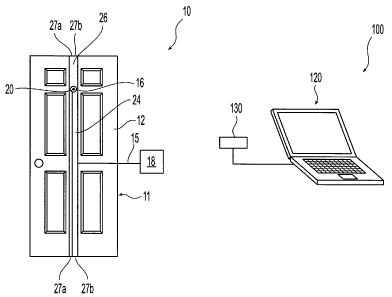
[0009] FIG. 1 is a front view of an exemplary door unit and viewing station of
the remote viewing system of the present invention;
-3-
CA 02532502 2006-O1-09
[0010] FIG. la is a partial front view of an exemplary door unit showing the
position of an exemplary camera lens;
[0011] FIG. 2 is a side section view of the door of FIG. 1 showing an
exemplary camera and associated processing board disposed between the door
panels;
[0012] FIG. 2a is a partial perspective view of the door of FIG. 1 showing the
venting holes disposed on the bottom of the door;
[0013] FIG. 3 is a schematic of the processing board of FIG. 2, showing the
main components of the board and the connections to a wireless driver;
[0014] FIG. 3a is a perspective view of the board and associated components
of FIG. 3;
(0015] FIG. 4 is a perspective view of an embodiment of the remote viewing
station comprising a laptop computer for use in receiving video and audio data
from
the wireless transmitter via a wireless USB connector.
DETAILED DESCRIPTION OF THE INVENTION
[0016] This invention is directed to a system for providing remote monitoring
of a doorway or entryway, in which a substantial portion of the system can be
installed within the panels of the door itself, thus rendering it unnoticeable
from the
exterior (as well as the interior) of the door. The system can be installed in
any of a
variety of standard door sizes, thus allowing a user to install the system
with a
minimum of disruption to the surroundings.
[0017] Referring to FIG. 1, an exemplary door unit 10 and remote viewing
station 100 are shown. The door unit 10 can comprise first and second door
panels
12, 14, and a video camera 16 disposed therebetween. The video camera 16 can
be
wireless or Bluetooth compatible, and can be controlled using a wireless
driver 18
(Fig. 3), such as a Bluetooth driver located adjacent to the door 10. The
wireless
driver 18 can power the camera 16, and can process the video data provided
from the
camera 16 and transmit that processed data to the remote viewing station 100
for
-4-
CA 02532502 2006-O1-09
review by a user. An example of an appropriate driver would be that contained
in the
VDH-2201 "Video Black Box," manufactured by ViVoDa Communications, Inc.
1072 S. De Anza Blvd., Ste. A107-301 San Jose, CA 95129. The remote viewing
station 100 can comprise a laptop computer 120 equipped with a wireless PC
card or a
S wireless USB adapter 130. The camera 16 can be any of a variety of
appropriate
miniature embeddable commercial video camera designs, such as bullet cameras
or
the like.
[0018] A microphone can also be provided as part of the door assembly, to
allow the user to monitor audio communications and/or to communicate with a
person
standing in the entryway. The microphone could connect to a port 184 on the
wireless driver 18 (see Figs. 3 and 3a), and would be controlled using the
driver 18 in
the same manner as the camera 16. For two-way communications, a speaker could
likewise be mounted in or near the door.
[0019] As noted the wireless driver 18 can be located adjacent to the door 10.
IS Thus, the driver can be located on or in an adjacent wall panel.
Alternatively, the
driver 18 could be located on the rear panel 14 of the door 10. Since the
driver 18
both powers and controls the camera 16, a connection between the two is
provided by
driver wires 24 that run between the door panels 12,14.
[0020] As can be seen from Fig. 1, the door 10 itself has the outward
appearance of a standard entryway door, and the camera 16 is positioned within
the
door 10 at about the same location as a standard viewing window ("peep hole").
A
custom port can be drilled in the door to fit the specific lens 17 size of the
camera
used. Thus, the system can be arranged so that a person approaching the door
will not
be aware of the camera or the associated electronics.
2S [0021] Referring to Fig. 2, the camera 16 can be directly mounted to the
door
10, or it can be located within a standard junction box 160 which itself is
embedded
within the door 10. A vent 26 can be provided within the door structure to
allow heat
generated by the camera 16 during operation to be adequately dissipated.
Proper heat
dissipation is important to ensure long term reliability of the device. The
vent 26 can
-S-
CA 02532502 2006-O1-09
comprise a vertical channel cut through the foam core 13 of the door. In the
illustrated embodiment, the channel runs the entire vertical height of the
door, and
connects to a pair of vent holes 27a, 6 located at the top and bottom ends of
the door.
The venting channel can run the entire thickness of the door panel, and can
also be
about 1-1/2" wide.
[0022] The door 10 has a foam core 13 which is sandwiched between the door
panels 12, 14. Suitable cavities are easily formed within the foam core 13 to
accommodate the components, as shown. Thus, the camera 16 and its junction box
160, along with the driver wires 24, can all be embedded within the foam. At
least a
portion of the camera should be exposed to the vent 26 to allow shedding of
heat.
[0023] One or more small openings can be provided in the hinge-side door
stile 11 (see Fig. 1), through which the driver wiring 24 can protrude for
connecting
to the wireless driver 18, which as noted can be mounted adjacent to the door
10.
Thus, the wiring 24 can pass from the door 10 directly through a corresponding
opening in the associated door jamb to connect to the wireless driver 18
located on, or
embedded within, the adjacent wall. Fig. 1 shows the wiring 24 exiting through
a
port 15 in hinge-side stile 11 near the center of the door 10.
[0024] Referring to FIG. 3, an exemplary schematic of the wireless driver 18
is shown. The driver 18 has a camera connection port 182 for receiving video
data
from the camera 16, an audio port 184 for receiving audio input from an
optional
microphone (not shown). A hard wire video output port 186 is also shown for
optional hard wired transmission of video data to a monitor. A wireless module
188
is provided for remote transmission of the collected video and/or audio data
to the
remote viewing station 100. Microprocessor 190 and memory 192 are also
provided.
The memory can be standard RAM, or can be flash-type memory for storing
instructions for the processor or for buffering audio and/or video data prior
to
transmission to the remote viewing station. An optional slot 196 can also be
provided
for addition of a separate memory card (not shown) for on-board storage of
audio and
video data.
-6-
CA 02532502 2006-O1-09
[0025] A power supply port 194 for connection to an external power supply is
provided. A backup battery power source 208 may also be provided on the driver
18
to prevent loss of data for cases in which external power is lost.
[0026] Additionally, a serial port 198 can be provided for connecting the
driver 18 to any of a variety of data acquisition devices, such as an external
data
logger (for long-term on-board storage of audio or video), or the like.
Alternatively, a
data modem can be connected via this port for transmitting audio or video data
directly to a user computer or network.
[0027] Although it is intended that the camera 16 and microphone will be
controlled using the Wireless driver 18 via the remote viewing station 100, a
port 200
can be provided for directly connecting a manual keypad 202 to the board for
controlling component functions directly. Additionally, an operational
indicator 204
can be connected to the driver 18 for providing constant indication of the
status of any
of the attached components. In the illustrated embodiment, the indicator 204
comprises a series of four LEDs. In one embodiment, a green indicator light
simply
would signal that the device is operational, while a red light would indicate
malfunction of one or more components. The indicator 204 could be mounted on
the
rear panel 14 of the door to provide a constant visual indication of the
status of the
device. In one embodiment, the indicator could provide a specific indication
when
the camera 16 or microphone are recording.
(0028] FIG. 5 shows an exemplary remote viewing station 100 comprising a
laptop computer 120 having a wireless USB connector 130 for receiving the
audio
and/or video data transmitted by the wireless module 188. A wireless-enabled
computer 100 (outfitted at the factory or retrofitted with a wireless PC card)
could
also be used, thus eliminating the need for the wireless USB connector 130.
The
audio and video data can be transmitted to a user having a wireless-enabled
PDA
(personal digital assistant, such as a Palm Pilot), or a cellular telephone.
[0029] The computer 120 the remote viewing station 100 will have
appropriate software loaded thereon for decompressing the transmitted audio
and
CA 02532502 2006-O1-09
video and for converting it into a form suitable for viewing, and which
further can be
made available for viewing over the Internet or other network.
[0030] Thus, once the audio and video data has been transmitted to the remote
viewing station 100 and converted, the information can be further provided via
the
S Internet, personal network, or the like, to any desired remote user having
access to the
Internet. For example, when the computer at the remote viewing station 100
receives
audio or video data from the driver 18, an alerting e-mail (or alternatively a
voice
mail or text message) could be sent from the computer 120 to a user situated
in a
different geographic location. The computer 120 could then make the
audio/video
available through a connection to a predefined Internet address. Based on the
alert,
the user could then receive the audio/video information in real time directly
on his or
her Internet connected electronic device. Alternatively the user could connect
remotely to their personal network to receive the audio/video information from
the
computer 120. Thus, the system could be used to allow a user to monitor the
entryway of their home, apartment, business, etc. while at work, on a business
trip, or
on vacation, anywhere in the world in which Internet access is available.
[0031] The system can be configured to operate continuously to collect video
and/or audio data from the camera 16 and microphone. Thus, in one embodiment,
the
processed audio and video data is continuously transmitted to the remote
viewing
station and is displayed to a user, and/or is recorded for later review as
necessary.
Alternatively, the processed audio and video data may be temporarily stored in
the
onboard memory card and batch-transmitted periodically.
[0032] Additionally, the system can be configured to have an operating mode
and a sleep mode. The system can be set up so that the normal system
configuration
is in sleep mode, which will reduce the power required to operate the system,
and will
eliminate the recording of a large amount of low-value audio and video data.
The
system can be "woken up" (i.e. switched from sleep mode to operating mode) by
a
triggering event, such as a person or object approaching the door. Thus a
motion
detector can be provided as a trigger, as can an audio receiver which is
configured to
trigger the device when it encounters sound above a certain decibel threshold.
_g_
CA 02532502 2006-O1-09
(0033] As an alternative to having only the camera 16 and associated driver
wiring 24 located within the door 10, the wireless driver 18 also could be
located
within the door, thus providing an entirely enclosed door without the need for
external
communications wiring. A power supply wire still may be needed for powering
the
device, and it is expected that a variety of appropriate powering arrangements
can be
provided. For example, a simple power supply wire could be provided having
sufficient play to allow opening and closing of the door without kinking the
wire and
without interfering with clearances between the stile 11 and the door jamb.
Alternatively, the power wiring could be integrated into one or more of the
hinges.
Alternatives to hard wiring are the use of solar power (for doors exposed to
the
outside). Additionally, the temperature differential between the front and
rear door
panels could be used as a further alternative source of power. It is also
contemplated
that inductive powering (e.g. using the normal opening and closing movement of
the
door) could be used to power the device.
[0034] It is noted that the remote viewing system will have applicability to a
wide range of applications, and is not limited to placement of a camera into
an
entryway door. Thus, a remote viewing video camera utilizing the described
Bluetooth or other wireless technology can be placed in window frames, walls,
patio
doors, garage doors, security doors, and the like. Additionally, the device
could be
used in a variety of automobile applications, and the video camera could be
installed
in automobile doors, hoods, front or rear bumpers, etc. Thus, the device can
be
implemented in nearly any application in which wireless remote viewing is
desired.
[0035] The present invention is also applicable to a system that allows a user
to remotely unlock the door to allow entry to a selected person. Thus, when
the
system is triggered to transmit audio or video data (e.g. when a person
approaches the
door), a signal can be sent via the computer 120 to prompt a remote user
(either via
the Internet using e-mail or by sending a text or voice mail message to the
user's cell
phone) informing them of such. The user can then remotely access the computer
120
using the Internet to view the audio and/or video data to determine the
identity of the
individual. If the user wishes to grant access to the individual, the user can
send an
instruction to the computer 120, again via the Internet, to unlock the door.
-9-
CA 02532502 2006-O1-09
[0036] The computer 120 could then send a signal to a controllable locking
mechanism located in the door or the door jamb that would unlock the door.
This
signal could be sent either via a hard wire connection or it could be a
digital wireless
signal, such as a Wi-Fi or Bluetooth wireless signal. The controllable locking
mechanism could be an electrically fired solenoid connected to a deadbolt or
other
latching element. The solenoid could be powered by a battery and could also
have a
sleep mode configuration that would enable the solenoid to use minimum power.
When the unlock signal is sent from the computer 120, the solenoid would "wake
up"
and operate to unlock the door. In one embodiment, the battery could be
rechargeable, or it could be powered using any of the powering arrangements
disclosed previously in relation to the driver 18 and camera.
[0037] Further, any of a variety of triggering mechanisms can be used for
triggering the computer 120 to send the previously described prompt to a
remote user.
For example, a motion detector or thermal detector could be used to detect
when an
individual approaches the door. Likewise, a doorbell press could serve as the
detector, as could a weight detector positioned in or beneath a door mat or
door step.
[0038] Accordingly, it should be understood that the embodiments disclosed
herein are merely illustrative of the principles of the invention. Various
other
modifications may be made by those skilled in the art which will embody the
principles of the invention and fall within the spirit and the scope thereof.
- 10-