Note: Descriptions are shown in the official language in which they were submitted.
CA 02532690 2006-O1-16
WO 2005/010284 PCT/US2004/022362
-1-
FLEXIBLE THERMALLY INSULATIVE AND WATERPROOF BARRIER
BACKGROUND OF THE INVENTION
The present invention relates to a thermally insulative and waterproof
barrier for protecting an exterior surface and, more particularly, to such a
barrier which is flexible.
It is known in the construction art to provide a thermally insulative and
waterproof barrier for protecting an exterior surface of a structure, whether
the
structure be a slab, a foundation, or a wall. Typically, the barrier is
substantially inflexible so that the several pieces forming the barrier, when
being installed, are placed both side-by-side and end-to-end to form butt
joints.
When butting the barrier pieces, the butting joints will be loose and, as a
result,
the barrier in the joint area is less- effective. Thus; moisture and cold air
can
work its way into and through the joint, thereby reducing or eliminating the
desired moisture and thermal barrier protection. The barrier cannot conform
itself to the subsoil or the foundation, but only hits or rests on the high
spots,
thereby leaving voids under the barner which can lead to breaking of the
barrier
in unsupported areas and possibly even structural problems with respect to
concrete or other material poured thereover since the material is not
installed to
an even thickness.
On the other hand, overlapping of substantially irdlexible barrier pieces
creates an unattractive appearance, allows ambient winds to drive under a
barrier piece to blow it out of position, and precludes the use of
conventional
flashing over the barrier. Most importantly, overlapping barner pieces may
interfere with formation of an operatively continuous barrier as substantially
inflexible barrier pieces will not substantially conform peripherally to a
subsoil,
foundation or wall, as necessary to provide an operatively continuous barrier.
Additionally, because of the voids caused by such overlapping of substantially
inflexible barrier pieces at and adjacent the overlap, even the limited amount
of
CA 02532690 2006-O1-16
WO 2005/010284 PCT/US2004/022362
-2-
walking on the barrier required for installation purposes may break the
barrier
pieces and thereby reduce the desired barrier properties.
As both butting joints and overlapping joints are not entirely satisfactory,
the industry has for the most part used butting joints, but then sealed the
butt
joints, for example, with an adhesive sealing tape or like sealant. For the
tape
or like sealant to be properly bonded with the butt joint, the exposed butt
joint
surface must be clean so as to be free of dirt, dust, etc. In addition to the
cost of
the sealing tape or like sealant, substantial time and labor must be expended
to
operatively seal the butt joints, thereby increasing the effective cost of the
barrier.
Additionally, in the known barrier materials, the thermal insulation
within is not operatively sealed against exposure to moisture, which can
deleteriously affect certain types of thermal insulation, such as aluminum.
Accordingly, it is an object of the present invention to provide a
thermally insulative and waterproof barrier for protecting an exterior surface
using a plurality of flexible blankets having overlapping edges, thereby to
avoid
the extra cost involved with the time, labor and materials required for
sealing of
butt joints.
Another object is to provide such a barrier which in a preferred
embodiment will substantially conform to a subsoil, foundation, or wall to
provide an operatively continuous burner.
A further object is to provide such a burner wherein in a preferred
embodiment the thermal insulation is sealed against attack by moisture.
It is also an object of the present invention to provide a burner which in a
preferred embodiment is simple and inexpensive to manufacture and use.
SUMMARY OF THE INVENTION
It has now been found that the above and related objects of the present
invention are obtained in a thermally insulative and waterproof burner for
protecting an exterior surface, comprising a plurality of generally
rectangular
flexible blankets. Each blanket defines a central body and a peripheral margin
CA 02532690 2006-O1-16
WO 2005/010284 PCT/US2004/022362
-3-
about the edges of the body. Edges of the bodies of adjacent blankets overlap.
The body includes at least one base layer of thermal insulation and two cover
layers of waterproof material, the cover layers being sealed together
peripherally about the base layer to form the peripheral margin and to exclude
water from the base layer.
In a preferred embodiment, the blankets are disposed with adjacent
blankets forming only a single pair of mutually overlapping edges. At least
one
of the blankets has all four edges overlapping the edges of other blankets.
Preferably, the overlapping edges (including the base layer) overlap by at
least
1.5 inches and by not more than 4.0 inches.
In another preferred embodiment, the peripheral margin of each blanket
is seamed and includes grommets extending therethrough. Securing means
extend through- at least some of the grommets for securing each blanket to one
of a substrate, a structural frame, and another blanket. A plurality of
fixation
means extend through each blanket body in order to fix the relative position
of
the base layer relative to the cover layers.
Preferably each blanket is sufficiently flexible to be rollable into a
generally cylindrical configuration, each blanket having a thickness of not
more
than 1.5 inches. Preferably the thermal insulation includes at least one
metallized surface of at least one cover layer. Preferably the waterproof
material is sheet-like, moistureproof and optionally impervious to soil gas.
BRIEF DESCRIPTION OF THE DRAWING
The above and related objects, features and advantages of the present
invention will be more fully understood by reference to the following detailed
description of the presently preferred, albeit illustrative, embodiments of
the
present invention when taken in conjunction with the accompanying drawing
wherein:
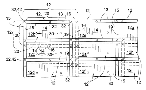
FIG. 1 is a fragmentary top plan view of a preferred layout of overlapping
flexible blankets to form a barrier according to the present invention;
CA 02532690 2006-O1-16
WO 2005/010284 PCT/US2004/022362
-4-
FIG. 2 is a top plan view, to an enlarged scale, of a single blanket, with
portions thereof removed to reveal details of internal construction; and
FIG. 3 is a fragmentary sectional view thereof taken along the lines 3-3 of
FIG. 2.
DETAILED DESCRIPTION OF THE PREFERRED EMBODIMENTS
Referring now to the drawing, and in particular to FIG. 1 thereof, therein
illustrated is a thermally insulative and waterproof barner according to the
present invention, generally designated by the reference numeral 10. The
barrier 10 is intended for the protection of an exterior (not shown)--for
example, a slab, foundation, wall or like structure, whether formed of
concrete,
brick or like construction material--against both heat (and loss of heat) and
moisture. The term "exterior" is used herein and in the claims to broadly
refer
to-any or all of he. outer surfaces, including the sides, top and bottom.
The barrier 10 is comprised of a plurality of generally rectangular,
substantially flexible blankets, generally designated 12, nine full blankets
being
illustrated in FIG. 1. Each blanket 12 defines a central body 14 having edges
l8
and a peripheral margin 16 extending about the edges 18. The blankets 12
forming the barrier 10 are disposed relative to one another such that adjacent
blankets 12 have overlapping central body edges 18, the overlap being
indicated
by the numeral 19. The overlapping central body edges 18 of adjacent blankets
12 may be on a longitudinal side 13 thereof, on a transverse end l5 thereof,
or
both. The term "overlapping" is used herein and' in the claims in its broad
sense
and includes both edges which go over other edges and edges which go under
other edges.
Accordingly, the peripheral margin 16 and central body edges 18 of the
centrally disposed blanket 12a overlaps to some degree each of the eight
contiguous blankets 12b through 12i. By way of contrast, a more isolated
corner blanket 12b may overlap only three contiguous blankets 12c, 12a and
12e, with the free edges 18 typically overlapping a wood construction frame or
the like (not shown). In other words, while at least one of the blankets 12
has
CA 02532690 2006-O1-16
WO 2005/010284 PCT/US2004/022362
-5-
all four central body edges 18 overlapping the edges 18 of other blankets 12,
other blankets 12 may have only two central body edges 18 overlapping other
blankets 12.
As best seen in FIG. 4, preferably the overlapping edges 18 of the central
bodies 14 of blankets 12 overlap by at least 1.5 inches and not more than 4.0
inches to provide an effective barrier seal, although lesser and greater
overlaps
maybe preferred in certain applications. ~f.course, the peripheral margins 16
overlap even more.
While the blankets have been illustrated as being of a common size and
configuration, clearly they may be provided in a variety of different sizes
and
confiigurations so that, with little if any modification, a variety of pre-
sized and
pre-configured blankets can be deployed to fully occupy the desired site.
Referring now to FIGS. 2 and 3 in particular, the central body 14 of each
blanket 12 includes at least one base layer 20 of thermal insulation and two
outer cover layers 22, 24 of waterproof material. The cover layers 22, 24
extend beyond the base layer 20 and are sealed together (e.g., heat sealed)
and/or seamed (e.g., sewn or stitched together) peripherally about the edges
18
of the base layer 20 to form the peripheral margin 16, thereby to exclude
water
and water vapor from the base layer 20. Preferably the cover layers 22, 24 are
coextensive.
The waterproof material of cover layers 22, 24 can be made of one or
more different types of sheet-like barrier materials which are effective
against
both water vapor and liquid water. The term "waterproof' as used herein and
in the claims refers to a barrier against both liquid and gaseous water (i.e.,
against both liquid water and water vapor). The material used must be flexible
and have a permeability rating of less than 1 (by Water Vapor Transmission
Test
ASTM- .E96) so that it is considered as a vapor barrier or vapor retarder.
Preferred waterproof materials include polyethylene, polyvinyl, polypropylene,
polyester, combinations thereof, sheeting made therefrom, and the like,
whether
or not metallized (for example, with light gauge aluminum). The waterproof
CA 02532690 2006-O1-16
WO 2005/010284 PCT/US2004/022362
-6-
cover layers 22, 24 are preferably not only moistureproof, but also impervious
to soil gases such as radon, methane and the like.
The thermal insulation base layer 20 can be made of one or more
conventional types of insulating materials. The key factor is, of course, that
it
must be sufficiently flexible so that it can be rolled and sufficiently thin
that
snugly overlapping joints can be made.
Preferred materials for base layer 20 include the flexible foams formed of
polyethylene, polypropylene, polystyrene, polyurethane, polyester, and the
like,
whether used in sponge, foam or bubble wrap Iayer form. As clearly illustrated
in FIG. 3, a preferred base layer 20 according to the present invention
includes
an outer pair of aluminized surface sub-layers 20a, 20b (on the facing inner
surfaces of the cover layers 22, 24), an inner pair of foam sub-layers 20c,
20d
(whether open-cell or closed-cell foam), and a bubble wrap sub-layer 20e
(either to one side of the pair of foam sub-layers 20c, 20d or therebetween).
These five sub-layers 20a-20e may be laminated together to form a unitary base
layer or merely lie in close juxtaposition. Thus, in a preferred construction
of
the blanket 12, the base layer 20 comprises the aluminized inner surfaces 20a,
20b of the cover layers 22, 24, and, intermediate the aluminized surfaces 20a,
20b, at least two sub-layers 20c, 20d of foam and at least one sub-layer 20e
of
bubble pack. The base layer 20 may, of course, consist of fewer or more than
five sub-layers.
As moisture is excluded from the thermal insulation base layer 20 by the
sealed waterproof cover layers 22, 24, the base layer 20 may be formed in part
of aluminum -- for example, thin aluminum foil adhered to the inner surface of
each waterproof cover layer 22, 24. Aluminum, a highly effective insulator or
reflector of radiant heat, is infamous for becoming dirty, dusty, dull or
damaged
during the typical construction process and thereafter. In the present
invention,
the aluminum of surfaces 20a, 20b is sealed within the blanket 12, and in
particular the envelope formed by the cover layers 22, 24, so that it is
protected
from direct contact with dirt, wet concrete or other moisture sources which
may
CA 02532690 2006-O1-16
WO 2005/010284 PCT/US2004/022362
-7_
adversely affect it. Where the aluminum is an aluminized surface 20a, 20b on
the inner surface of the cover layers 22, 24, it may be expedient to extend
the
aluminized surfaces 20a, 20b out into the peripheral margins 16 along with the
cover layers 22, 24, as illustrated. Alternatively, the aluminized surfaces
20a,
20b may be co-extensive only with the base layer 20 (that is, not extend into
the
peripheral margins 16).
Preferably the central body 14 of each blanket 12 has a thickness of not
more than 1.5 inches. Thus, the thickness increase of an overlapped joint
(relative to that of a single blanket 12) is at most 1.5 inches except for
those
corners where three blankets 12 overlap and the corner overlap is at most 3.0
inches.
In order to prevent shifting of the base layer 20 within the envelope
formed by the cover layers 22, 24, a pluraliiy.of fixation means 30 (best
illustrated in FIGS. 2 and 3) preferably extend through the central body 14 of
each blanket 12, thereby to fix the relative position of the base layer 20
relative
to the cover layers 22, 24. The fixation means 30 may be a simple solid
plastic
rod extending through the body 14 and held in place by means of enlarged
heads or buttons affixed thereto outwardly of the cover layers 22, 24.
In order to fix the blanket peripheral margins 16 in place -- either to a
substrate or a framework -- grommets 32 preferably extend through each
peripheral margin 16 of each blanket 12. The grommets 32 pass through the
cover layers 22, 24 (but not the base layer 20) and are used to fix the
relative
position of the blankets 12 with respect to one another. Conventional securing
means 42 (such as pins or stakes) may be inserted through the grommets 32
into the substrate or a framework (not shown) at the edge of the barrier 10.
It
will be appreciated that, if desired, the securing means 42 passing through a
grommet 32 of one blanket 12 will pass through an aligned grommet 32 of an
adjacent blanket 12 to fix the relative disposition of the two blankets,
assuming
the two grommets 32 have been appropriately placed on the respective blankets
to take into account the desired body overlap.
CA 02532690 2006-O1-16
WO 2005/010284 PCT/US2004/022362
_g_
The substantial flexibility of the blankets 12 enables them to be formed,
stored, transported and deployed in larger sizes (e.g., up to 6 x 50 feet)
relative
to a conventional more rigid, non-rollable barrier piece which is typically
limited to no more than 8 feet in length. Accordingly, the larger blankets of
the
present invention can more easily and rapidly be installed, thereby saving
time
and labor expenses.
The blanket configuration can easily be modified to compensate for
obstructions, such as pipes, drains and the like, simply using a urility knife
or a
pair of scissors to trim the blankets about the obstruction, and then applying
a
moistureproof sealing tape to seal the trimmed area. Such a modification can
usually be performed economically at the construction site without the use of
special tools (such as the saw or hot knife typically required to modify the
configuration of a rigid insulation) . _
The substantial flexibility of the blanket enables it to be delivered to a
construction site in a tight roll and to be so stored at the construction site
prior
to use. When used, the blanket conforms perfectly to the subsoil, around the
foundation, and up a concrete or brick wall. The grommets enable the blankets
to be staked down to a substrate or wooden framework at the job site in order
to prevent them from being blown out of position by ambient winds, etc. The
overlapping joints of the barrier provide a relatively attractive finish to
the
exterior at the construction site, prior to covering of the barrier, and avoid
the
unsightly appearance of the sealants. The staked-down barrier can be walked
on without damage thereto, if desired, since there are essentially no voids
beneath the blankets.
The substantially uniform thickness of the barrier enables a relatively
even pour of concrete over the barrier, thereby to form a concrete slab of
substantially uniform strength. The overlapping of the edges provides both a
very high R-V value and an effective barrier against liquid water, moisture
vapor
and optionally soil gases (e.g., radon, methane and the like). Aluminum
flashing (thicker and more rigid than aluminum foil) may easily be installed
CA 02532690 2006-O1-16
WO 2005/010284 PCT/US2004/022362
-9-
over the barrier 10 since the overlapping edges of the blankets cause only a
minor variation (typically not exceeding 1.5 inches, the blanket thickness) in
the
thickness of the barrier.
To summarize, the present invention provides a thermally insulative and
waterproof barrier for protecting an exterior surface using a plurality of
flexible
sheets having overlapping edges, thereby to avoid the extra expense involved
with the time, labor and materials required for the sealing of butt joints.
The
burner will conform substantially to a subsoil, foundation or wall to provide
an
operatively continuous barrier, the thermal insulation within the barrier
being
sealed against attack by moisture. The burner is simple and inexpensive to
manufacture and use.
Now that the preferred embodiments of the present invention have been
shown and described in detail, various modifications and improvements therein
will become readily apparent to those skilled in the art. Accordingly, the
spirit
and scope of the present invention is to be construed broadly and limited only
by the appended claims, and not by the foregoing specification.