Note: Descriptions are shown in the official language in which they were submitted.
CA 02532775 2006-01-31
METHOD AND APPARATUS FOR DELIVERING TWO FUELS
TO A DIRECT INJECTION INTERNAL COMBUSTION ENGINE
Field of the Invention
[0001] The present invention relates to a method and apparatus for
delivering two fuels to a direct injection internal combustion engine. More
specifically, the invention relates to a fuel system that keeps the two fuels
separate until they are separately and independently introduced directly
into the engine's combustion chamber and a drain system for draining both
fuels from the fuel system.
Background of the Invention
[0002] Engines that burn diesel fuel are the most popular type of
compression ignition engines. So-called diesel engines introduce fuel at
high pressure directly into the combustion chamber. Diesel engines are
very efficient because this allows high compression ratios to be employed
without the danger of knocking, which is the premature detonation of the
fuel mixture inside the combustion chamber. Because diesel engines
introduce their fuel directly into the combustion chamber, the fuel
injection pressure must be greater than the pressure inside the combustion
chamber when the fuel is being introduced, and, for liquid fuels the
pressure must be significantly higher so that the fuel is atomized for
efficient combustion.
[0003] Diesel engines are favored by industry because they are proven
performers that are known to give operators the best combination of
power, performance, efficiency and reliability. For example, diesel
engines are generally much less expensive to operate compared to gasoline
fueled spark-ignited engines, especially in high-use applications where a
lot of fuel is consumed. However, a disadvantage of diesel engines is that
they can produce more pollution, such as particulate matter (soot) and
CA 02532775 2006-01-31
-2-
NOx, which are subject to increasingly stringent regulations that require
such emissions to be progressively reduced over time. To comply with
such regulations, engine manufacturers are developing catalytic converters
and other aftertreatment devices to remove pollutants from the exhaust
stream. Improvements to the fuel are also being introduced, for example to
reduce the amount of sulfur in the fuel, to prevent sulfur from de-
activating catalysts and to reduce air pollution. Research is being
conducted to improve combustion efficiency to reduce engine emissions,
for example by making refinements to engine control strategies. However,
most of these approaches add to the capital cost of the engine and/or the
operating costs.
[0004] Recent developments have been directed to substituting some of
the diesel fuel with cleaner burning gaseous fuels such as, for example,
natural gas, pure methane, butane, propane, hydrogen, and blends thereof.
However, in this disclosure "gaseous fuel" is defined more broadly than
these examples, as any combustible fuel that is in the gaseous phase at
atmospheric pressure and ambient temperature. Since gaseous fuels
typically do not auto-ignite at the same temperature and pressure as diesel
fuel, a small amount of liquid fuel can be introduced into the combustion
chamber to auto-ignite and trigger the ignition of the gaseous fuel. One
approach for consuming gaseous fuel on board a vehicle involves
introducing the gaseous fuel into the engine's intake air manifold at
relatively low pressures. However, with this approach, engines have been
unable to match the performance and efficiency of diesel engines. In a
preferred method, it is possible to substantially match the performance and
efficiency of a conventional diesel engine by delivering a high-pressure
gaseous fuel to an engine for injection directly into the combustion
chamber.
CA 02532775 2006-01-31
-3-
[00051 A problem with delivering two different fuels for injection directly
into the combustion chambers of an internal combustion engine, is that it
can be difficult to find the physical space for two fuel injection valves per
cylinder and space near the fuel injection valves to provide two high
pressure fuel rails in addition to drain lines for taking away fuel that may
leak from the fuel injection valves and fluid that is drained from control
chambers of hydraulically actuated fuel injection valves.
[0006] High-pressure liquid fuel that leaks from a conventional diesel fuel
injection valve is normally collected and directed to a drain rail that
returns the fuel back to a fuel tank. Such a drain can also be employed to
collect diesel fuel that is drained from a control chamber of a hydraulic
actuator for the valve needle, when the diesel fuel is also employed as a
hydraulic fluid for actuating the fuel injection valve. In a conventional
diesel engine, the low-pressure drain rail adds to the piping around the fuel
injection valves, but this is manageable with only one fuel. With an
engine that is fueled with a liquid fuel and a gaseous fuel, there is a need
to
drain liquid fuel and vent high-pressure gaseous fuel that leaks from the
gaseous fuel injection valve. If gaseous fuel leaks from a gaseous-fuel
injection valve and is not collected and somehow vented, the high-pressure
gaseous fuel can collect between the fuel injection valve body and the
cylinder head, exerting forces on the fuel injection valve that can act
against the clamps that are typically employed to hold the fuel injection
valve in position. For a common rail direct injection fuel system, the
gaseous fuel can be delivered to the fuel injection valve at a pressure of at
least 20 MPa (about 3000 psi), and depending upon the engine
characteristics, such as its compression ratio, for some engines the desired
fuel injection pressure can be even higher. Accordingly, there is a need to
provide for a means for venting any gaseous fuel that leaks from the fuel
CA 02532775 2006-01-31
-4-
injection valve without adding to the complexity of the piping to and from
the fuel injection valves.
Summary of the Invention
[0007] An apparatus is provided for separately delivering a liquid fuel and
a gaseous fuel into a combustion chamber of an internal combustion
engine. The apparatus comprises a liquid-fuel supply system, a gaseous-
fuel supply system and a drain system. The liquid-fuel supply system
comprises a liquid-fuel storage vessel that is fillable with the liquid fuel;
a
liquid-fuel pump with a liquid-fuel inlet fluidly connected by a liquid-fuel
passage to the liquid-fuel storage vessel; and a liquid-fuel rail fluidly
connected to an outlet of the liquid-fuel pump and to a liquid-fuel
accumulator chamber inside at least one liquid-fuel injection valve that is
operable to introduce the liquid fuel from the liquid-fuel accumulator
chamber through a first nozzle directly into the combustion chamber. The
gaseous-fuel supply system comprises a gaseous-fuel supply pipe; a
gaseous-fuel pressurizing device with a gaseous-fuel inlet fluidly
connected by a gaseous-fuel passage to the gaseous-fuel supply pipe; and a
gaseous-fuel rail fluidly connected to an outlet of the gaseous-fuel
pressurizing device and to a gaseous-fuel accumulator chamber inside at
least one gaseous-fuel injection valve that is operable to introduce the
gaseous fuel from the gaseous-fuel accumulator chamber through a second
nozzle directly into the combustion chamber. The drain system comprises
a drain rail with a receiving end fluidly connected to at least one drain
passage from the liquid-fuel injection valve and at least one drain passage
from the gaseous-fuel injection valve, and a discharge end fluidly
connected to the liquid-fuel storage vessel; a venting device through which
CA 02532775 2006-01-31
-5-
gaseous fuel can be vented from the drain rail or the liquid-fuel storage
vessel.
[0008] In a preferred embodiment of the apparatus, the gaseous-fuel
injection valve comprises a body with a drain passage with an opening to
the outside of the body to recover gaseous fuel that leaks from the body
and to direct the gaseous fuel through the drain passage to the drain rail.
[0009] The gaseous-fuel supply system can comprise a gaseous-fuel
storage vessel that communicates with the gaseous-fuel supply pipe and
that is fillable with the gaseous fuel or the gaseous-fuel supply pipe can be
connected to a pipeline distribution network. If a gaseous-fuel storage
vessel is part of the gaseous-fuel supply system, the gaseous-fuel storage
vessel can be a thermally insulated vessel in which a liquefied gaseous fuel
can be stored at cryogenic temperatures, and the gaseous-fuel pressurizing
device is a pump for pumping the liquefied gaseous fuel at cryogenic
temperatures. The gaseous-fuel supply system can further comprise a heat
exchanger disposed between the pump and the gaseous-fuel rail for
heating the gaseous fuel after it is discharged from the pump.
[0010] An advantage of storing a gaseous fuel in liquefied form at a
cryogenic temperature is that a much higher energy density can be
achieved compared to the same gaseous fuel stored at high pressure in the
gaseous phase. However, if the gaseous-fuel supply system is for a vehicle
with only short range routes and/or where high-pressure gaseous fuel is
readily available for re-fueling, it is possible to use a gaseous-fuel storage
vessel that is a pressure vessel in which the gaseous fuel can be stored
under pressure and in such embodiments the gaseous-fuel pressurizing
device can be a compressor. In some markets this can be a preferred
approach if there is greater familiarity with handling high pressure gases,
versus cryogenic fluids, and where there is an established re-filling
CA 02532775 2006-01-31
-6-
network for gaseous fuels. When a compressor is employed to pressurize
the gaseous fuel the gaseous-fuel supply system can further comprise a
heat exchanger disposed between the compressor and the gaseous-fuel rail
for cooling the gaseous fuel after it is discharged from the compressor.
[0011] In preferred embodiments, a portion of the liquid-fuel rail
comprises a bore disposed within a cylinder head of the internal
combustion engine. An advantage of having the liquid-fuel rail disposed
within the cylinder head comprising either a bore in the cylinder head or
pipes disposed in opening provided in the cylinder head is that it simplifies
the arrangement above the cylinder head which includes ignition devices
such as spark plugs or ow plugs, actuators for the fuel injection valves
and actuators for the engine intake and exhaust valves. In a preferred
embodiment the engine has a plurality of cylinder heads with each one of
the plurality of cylinder heads being associated with a plurality of in-line
cylinders and the liquid-fuel rail comprises a bore through one of the
plurality of cylinder heads for delivering the liquid fuel to a plurality of
liquid-fuel injection valves that are associated with the at least one of the
plurality of cylinder heads.
[0012] In addition to a portion of the liquid-fuel rail being disposed within
the cylinder head, similar advantages can be realized if a portion of the
gaseous-fuel rail and/or the drain rail comprises a bore disposed with the
cylinder head. That is, in a preferred embodiment, portions of each one of
the liquid-fuel rail, the gaseous-fuel rail, and the drain rail all comprise
respective bores disposed within the cylinder head.
[0013] In preferred embodiments, the venting device for venting gaseous
fuel from the drain rail or the liquid-fuel storage vessel comprises a
pressure relief valve. If associated with the liquid-fuel storage vessel, the
pressure relief valve can be mounted to vent gas from a vapor space of the
CA 02532775 2006-01-31
-7-
liquid-fuel storage vessel. Instead of a pressure relief valve, the venting
device can be a roll-over vent valve mounted on top of the liquid-fuel
storage vessel. The roll-over vent valve can comprise a valve meinber that
is actuated by gravity. The venting device can further comprise a vent
pipe connecting the venting device to a holding tank or to the gaseous-fuel
supply pipe for re-introduction into the gaseous-fuel supply system.
[0014] The venting device can further comprises a gas-liquid separator
disposed in a drain pipe that connects the drain rail to the liquid-fuel
storage vessel. In this embodiment the gas-liquid separator has a liquid
outlet communicating with the liquid-fuel storage vessel and a gas outlet
communicating with a vent pipe.
100151 In preferred embodiments, the liquid-fuel injection valve and the
gaseous-fuel injection valve are housed within one valve body. That is,
the liquid-fuel injection valve and the gaseous-fuel injection valve are
integrated within one valve assembly that can be installed in one opening
in the cylinder head. The liquid-fuel injection valve and the gaseous-fuel
injection valve can be co-axial with the liquid-fuel injection valve at the
centre and the gaseous-fuel injection valve disposed in an annular space
around the liquid-fuel injection valve. In this embodiment the liquid-fuel
injection valve comprises a nozzle that is movable to function as the
needle for the gaseous-fuel injection valve. The liquid-fuel injection valve
and the gaseous-fuel injection valve are preferably independently operable
so that the gaseous-fuel can be injected independently from the liquid fuel
and the respective timing for the liquid and gaseous fuel injection events is
also independent.
[0016] The liquid-fuel injection valve can comprise a valve needle that is
spring biased and hydraulically actuated by manipulating hydraulic fluid
pressure within a first control chamber between two pressures. The first
CA 02532775 2006-01-31
-8-
control chamber can be fluidly connectable by fluid passages with the
drain rail and the liquid-fuel rail, and a control valve associated with at
least one of the fluid passages, is operable to switch hydraulic fluid
pressure between liquid-fuel rail pressure and drain rail pressure.
Similarly, the gaseous-fuel injection valve can comprise a valve needle
that is spring biased and hydraulically actuated by manipulating hydraulic
fluid pressure within a second control chamber between two pressures.
The second control chamber can be likewise fluidly connectable by fluid
passages with the drain rail and the liquid-fuel rail, and a control valve
associated with at least one of the fluid passages, is operable to switch
hydraulic fluid pressure between liquid-fuel rail pressure and drain rail
pressure.
[0017] A method is provided of separately delivering a liquid fuel and a
gaseous fuel into a combustion chamber of an internal combustion engine.
The method comprises supplying a liquid fuel from a liquid-fuel storage
vessel, pumping the liquid fuel and delivering the liquid fuel at injection
pressure from the liquid-fuel storage vessel to a liquid-fuel injection valve
through a liquid-fuel rail, and actuating the liquid-fuel injection valve to
introduce the liquid fuel directly into the combustion chamber. The
method further comprises supplying a gaseous fuel from a gaseous-fuel
supply pipe, pressurizing the gaseous fuel, delivering the gaseous fuel at
injection pressure from the gaseous-fuel supply pipe to a gaseous-fuel
injection valve through a gaseous-fuel rail, and actuating the gaseous-fuel
injection valve to introduce the gaseous fuel directly into the combustion
chamber. In addition, the method comprises collecting in a drain rail,
liquid fuel and gaseous fuel from the liquid-fuel injection valve and the
gaseous-fuel injection valve respectively, and directing liquid fuel from the
CA 02532775 2006-01-31
-9-
drain rail to the liquid-fuel storage vessel, and directing gaseous fuel from
the drain rail to a vent pipe.
[0018] According to the method, gaseous fuel can be supplied to the
gaseous-fuel supply pipe from a distribution pipe, or in preferred
embodiments, the method can further comprise supplying the gaseous fuel
to the gaseous-fuel supply pipe from a gaseous-fuel storage vessel.
[0019] The method can further comprise venting gaseous fuel through the
vent pipe when gas pressure exceeds a predetermined set point. In
addition, the method can further comprise directing the gaseous fuel from
the vent pipe to a holding tank or to the gaseous fuel supply pipe.
[0020] In preferred methods pressure within the liquid-fuel storage vessel
is maintained at or near atmospheric pressure by connecting the vent pipe
to the liquid-fuel storage vessel. The method can further comprise
preventing liquid fuel from escaping through the vent line by blocking
fluid flow through the vent pipe if the liquid-fuel storage vessel tips onto
its side or up-side-down.
[0021] Like in the preferred apparatus, in-a preferred method comprises
directing at least one of the liquid fuel and the gaseous fuel through a bore
in a cylinder head of the engine that is at least a portion of a respective
one
of the liquid-fuel rail, the gaseous-fuel rail, and the drain rail. More
preferably, each one of the liquid-fuel rail, the gaseous-fuel rail, and the
drain rail comprises at least a portion that is a bore provided within a
cylinder head of the engine.
[0022] Preferred methods comprise hydraulically actuating at least one of
the liquid-fuel injection valve and the gaseous-fuel injection valve by
controlling liquid-fuel pressure in a control chamber associated with a
plunger that is associated with a fuel injection valve needle.
CA 02532775 2006-01-31
-10-
[0023] Preferred methods further comprise supplying high pressure liquid
fuel to the control chamber from the liquid-fuel rail, draining liquid fuel
from the control chamber to the drain rail, and operating a control valve to
switch liquid-fuel pressure inside the control chamber between liquid-fuel
rail pressure and drain rail pressure, wherein drain rail pressure is lower
than liquid-fuel rail pressure.
[0024] An objective of the presently disclosed invention is to reduce air
pollution by substituting cleaner burning gaseous fuels instead of
conventional liquid fuels like diesel, for most of the fuel that is consumed
by the engine. Accordingly, the liquid fuel that is delivered to the engine
constitutes only a small quantity of fuel that is employed as a pilot fuel to
ensure ignition of the gaseous fuel. The liquid fuel can be conventional
diesel fuel, or other liquid fuels such as kerosene, biodiesel, or
dimethylether, that will auto-ignite in a compression ignition engine. By
way of example, the liquid fuel can be, on average, less than 10% of the
total fuel consumed by the engine.
[0025] There can also be economic advantages associated with
substituting a gaseous fuel for diesel fuel, since in many markets around
the world, gaseous fuels are less expensive than diesel fuel on an energy
basis, and if the gaseous fuels can be consumed in an engine with the same
efficiencies as diesel fuels, this can result in a significant savings in the
operating costs for the engine. In addition, geographically, compared to
oil, natural gas as a resource is more broadly available, with many more
countries having larger natural gas reserves than oil reserves, providing a
potentially more secure supply of fuel.
CA 02532775 2006-01-31
-11-
Brief Description of the Drawinas
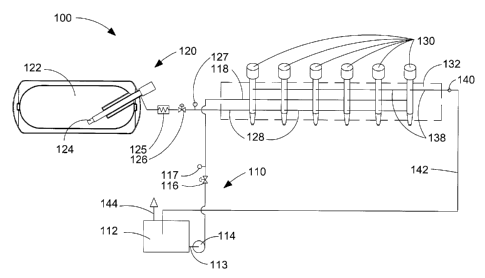
[0026] Figure 1 is a schematic diagram of an apparatus for delivering a
liquid fuel and a gaseous fuel into a combustion chamber of an internal
combustion engine. The apparatus comprises: a liquid-fuel supply system
comprising a liquid-fuel storage vessel, a liquid-fuel pump, a liquid-fuel
rail, and a liquid-fuel injection valve; a gaseous-fuel supply system
comprising a gaseous-fuel cryogenic storage vessel for storing a liquefied
gaseous fuel, a pump for pumping liquefied gaseous fuel, a gaseous-fuel
rail, and a gaseous fuel injection valve; and a drain rail for returning low
pressure liquid fuel and vented gaseous fuel to the liquid-fuel storage
vessel.
[0027] Figure 2 is a schematic diagram of an apparatus for delivering a
liquid fuel and a gaseous fuel into a combustion chamber of an internal
combustion engine. The apparatus of Figure 2 is similar to that of Figure 1
with a few exceptions such as-that the gaseous fuel beingis stored in the
gaseous phase and pressurized by a compressor instead of a pump.
[0028] Figure 3 is a schematic view of a fuel injection valve that has co-
axial liquid-fuel and gaseous-fuel injection valves, and side ports for
communicating with fuel supply rails and drain rails that can be routed
through the engine's cylinder head.
Detailed Description of Preferred Embodiment(s)
[0029] Figure 1 is a schematic view of apparatus 100, which delivers a
liquid fuel and a gaseous fuel into a combustion chamber of an internal
combustion engine. Apparatus 100 comprises liquid-fuel supply system
110, which itself comprises liquid-fuel storage vessel 112, suction line
113, liquid-fuel pump 114, pressure control valve 116, optional pressure
sensor 117, and liquid-fuel rail 118. Apparatus 100 further comprises
CA 02532775 2006-01-31
-12-
gaseous-fuel supply system 120, which itself comprises gaseous-fuel
storage vessel 122, gaseous-fuel pump 124, heat exchanger 125, pressure
control valve 126, optional pressure sensor 127, and gaseous-fuel rail 128.
Optional pressure sensors 117 and 127 can be employed to respectively
monitor liquid and gaseous fuel pressure to ensure that liquid-fuel supply
system 110 and gaseous-fuel supply system 120 are functioning normally.
[0030] The engine comprises a plurality of fuel injection valves 130,
which are mounted in cylinder head 132. In Figure 1, cylinder head 132 is
schematically shown in dashed outline. In the illustrated embodiment the
engine can have a cylinder block with six in-line cylinders (not shown),
with one fuel injection valve associated with the combustion chamber
defined by each cylinder. In the illustrated embodiments, each fuel
injection valve 130 is capable injecting the liquid fuel and the gaseous fuel
into a respective combustion chamber (not shown), so each fuel injection
valve 130 is associated with liquid-fuel rail 118 and gaseous-fuel rail 128.
Even though the liquid-fuel injection valve and the gaseous-fuel injection
valve are integrated into a single dual fuel injection valve, the liquid-fuel
injection valve and the gaseous-fuel injection valve are preferably
independently operable to separately introduce the liquid fuel and gaseous
fuel into the combustion chambers. This allows separate timing for the
liquid fuel and gaseous fuel injection events and more precise control over
the quantity of each fuel that is injected into the combustion chambers.
[0031] Persons skilled in the technology will understand that the disclosed
apparatus and method can be applied to internal combustion engines of
different sizes and with any number of cylinders. For engines with more
than one cylinder head, fuel supply and drain rails can have branches
associated with each cylinder head.
CA 02532775 2006-01-31
-13-
[0032] Drain rail 138 collects liquid fuel and/or gaseous fuel from drain
passages provided internal to fuel injection valves 130 (as shown in Figure
3). Fuel in drain rail 138 is at a lower pressure than that of the fuels in
fuel
supply rails 118 and 128. Valve 140 ensures that a predetermined
minimum back-pressure is maintained during normal operation to prevent
cavitation inside the internal passages of fuel injection valves 130. Valve
140 can be a one-way check valve to ensure that fluid only flows in one
direction from drain rail 138 to drain pipe 142. Fluid flows through drain
pipe 142 to liquid-fuel storage vessel 112. Liquid-fuel storage vessel 112
is equipped with vent 144 so that the fuel can be stored at or near
atmospheric pressure. Vent 144 can be a simple open vent tube, but
preferably vent 144 further comprises a valve. For example, the valve can
be a pressure relief valve or a roll-over valve that has a gravity actuated
valve member that closes if the liquid-fuel storage vessel is rolled onto its
side or inverted (to prevent fuel spillage from a vehicle fuel tank if the
vehicle rolls over). If the vent pipe is a simple open vent tube or a vent
tube with a gravity-actuated roll-over valve, the liquid fuel is stored at
atmospheric pressure. If a pressure relief valve is employed, vapor
pressure in the liquid-fuel storage vessel can increase until it is just below
the predetermined set point that is the relief pressure, which is preferably
near atmospheric. To comply with local regulations, the set point for the
relief pressure is at least the requisite factor of safety below the burst
pressure of the liquid-fuel storage vessel.
[0033] Vent 144 can also be connected to a holding tank for storing
gaseous fuel instead of venting it to atmosphere. In another embodiment
(not shown) a gas-liquid separator can be disposed in drain pipe 142
between drain rai1132 and liquid-fuel storage vessel 112, to separate the
CA 02532775 2006-01-31
-14-
collected gaseous fuel from drain pipe 142 before it reaches liquid-fuel
storage vessel 112.
[0034] The amount of liquid fuel that flows to drain can be much more
than the amount of gaseous fuel that flows to drain, because in addition to
small amounts of fuel that may leak from the integrated fuel injection
valve assembly, in a preferred embodiment the liquid fuel can also be
employed as the hydraulic fluid for actuating the liquid-fuel injection valve
needle and/or the gaseous-fuel injection valve needle. Hydraulically
actuated fuel injection valves are well known. By controlling hydraulic
fluid pressure in a control chamber to switch hydraulic fluid pressure from
high-pressure to drain pressure, and vice versa, a fuel injection valve
needle can be actuated between open and closed positions under the
influence of fuel pressure and/or springs that also exert forces that act on
the valve needle. When liquid fuel, serving as hydraulic actuation fluid, is
drained from a control chamber for actuating the associated valve needle,
the liquid fuel from the control chamber can be drained through drain rail
138.
[0035] In another embodiment, not shown, the liquid-fuel injection valve
can be separate from the gaseous-fuel injection valve. However, such an
embodiment is less preferred for a number of reasons. For example,
separate liquid-fuel and gaseous-fuel injection valves complicate the
arrangement of drain rail 138, which in accordance with the presently
disclosed invention is connected to drain passages from both the liquid-
fuel injection valve and the gaseous-fuel injection valve. Separate liquid-
fuel and gaseous-fuel injection valves also complicate the supply of high
pressure hydraulic fluid if the liquid-fuel and gaseous-fuel injection valves
are both hydraulically actuated. A further disadvantage of separate liquid-
fuel and gaseous-fuel injection valves is that more space in the cylinder
CA 02532775 2006-01-31
-15-
head is required to mount two injection valves per cylinder instead of one,
whereas one integrated dual fuel injection valve can be made to fit in the
same location as a conventional diesel-only fuel injection valve, reducing
the modifications needed to convert a conventional diesel engine into an
engine that substitutes a gaseous fuel for most of the diesel fuel.
[0036] The method of operating apparatus 100 is described as follows.
Fuel injection valves 130 are preferably so-called common rail injection
valves. That is, the fuel is supplied at injection pressure to each one of
fuel injection valves 130 through the same fuel rail. People familiar with
this technology will understand that the term "rail" as it is defined herein
means a conduit, bore, or pipe that functions as a manifold for distributing
fuel to the fuel injection valves. Accordingly, when the engine is running,
liquid-fuel rail 118 and gaseous-fuel rail 128 are each filled with a
pressurized fuel at injection pressure, and fuel can be injected by actuating
a respective valve needle from a closed position to an open position. The
term "rail" can also be used to describe a drain manifold, such as drain rail
13 8, which communicates with a drain port of each one of the fuel
injection valves for collecting fluid from drain passages provided within
the fuel injection valves.
[0037] Liquid fuel in liquid-fuel rail 118 is maintained at the desired
injection pressure by operating pump 114 and by operation of pressure
control valve 116, which is disposed in the liquid-fuel delivery pipe
between pump 114 and liquid-fuel rail 118. Pressure control valve 116
can be set to control liquid-fuel pressure in liquid-fuel rail 118 so that it
is
maintained at a predetermined fixed pressure when the engine is running.
In other embodiments, pressure control valve 116 can be controlled by an
electronic controller to regulate liquid-fuel pressure within liquid-fuel rail
118 responsive to engine operating conditions, for example to adjust
CA 02532775 2006-01-31
-16-
pressure within liquid-fuel rail 118 to predetermined pressures defmed by
an engine map.
[0038] In the schematic illustration of Figure 1, the fuel rails are shown
extending through the six fuel injection valves 130, and in the physical
arrangement passages can be provided around the fuel injection valves in
annular recesses provided in cylinder head 132 around fuel injection
valves 130 or by annular passages provided between land areas protruding
from the surface of fuel injection valves 130.
[0039] Gaseous fuel in gaseous-fuel rail 128 is maintained at the desired
injection pressure by operating pump 124 and by operation of pressure
control valve 126, which is located in the gaseous-fuel delivery pipe
between heat exchanger 125 and gaseous-fuel rail 128. When the liquid-
fuel injection valve and the gaseous-fuel injection valve are integrated into
a dual fuel injection valve assembly, to reduce pressure differentials
between the two high-pressure fuels, gaseous-fuel injection pressure is
preferably set to be equal or slightly less than the liquid-fuel injection
pressure, so that gaseous fuel does not leak into the liquid-fuel passages.
An apparatus and method of dynamically controlling liquid-fuel and
gaseous-fuel pressures in an integrated liquid-fuel and gaseous-fuel
injection valve is disclosed in co-owned United States Patent No.
6,298,833. Accordingly, the operation of pressure control valve 126 is
preferably linked to the operation of pressure control valve 116, or one
pressure control valve can be employed to maintain a pressure differential
between the pressure in liquid-fuel rail 118 and the pressure in gaseous-
fuel rail 128.
[0040] Like liquid-fuel rail 118, in the schematic illustration of Figure 1,
gaseous-fuel rail 128 is shown extending through the six fuel injection
valves 130, and in the physical arrangement passages can be provided
CA 02532775 2006-01-31
-17-
around the fuel injection valves in annular recesses provided in cylinder
head 132 around fuel injection valves 130 or by annular passages provided
between land areas protruding from the surface of fuel injection valves
130.
[0041) Gaseous-fuel storage vessel 122 can be a double-walled vacuum
insulated vessel for storing a liquefied gaseous fuel at cryogenic
temperatures and relatively low pressures. Pump 124 is immersed in the
liquefied gas and in preferred embodiments is a reciprocating piston pump.
The pump drive is located outside of gaseous-fuel storage vessel 122 and
connected by an elongated shaft, the length of which helps to reduce heat
leak into the cryogen space defined by gaseous-fuel storage vessel 122,
and freezing of the drive unit. For actuating pump 124 at the desired
speeds, the drive unit is preferably a hydraulic motor with a reciprocating
piston.
[0042] Figure 2 is a schematic view of apparatus 200 which is another
preferred embodiment for delivering a liquid fuel and a gaseous fuel to a
direct injection internal combustion engine. Like-illustrated components
with like reference numbers separated by multiples of one hundred refer to
like components unless otherwise noted. For example, liquid-fuel supply
system 210 is essentially the same as liquid-fuel supply system 110 that is
shown in Figure 1. Liquid fuel is stored in liquid-fuel storage vessel 212
and liquid fuel flows through suction pipe 213 to pump 214, which is
operable to supply liquid fuel and maintain the desired pressure in liquid-
fuel rai1218. Liquid-fuel pressure control valve 216 which is disposed in
the liquid-fuel supply pipe between pump 214 and liquid-fuel rai1218 is
operable to regulate liquid-fuel pressure in liquid-fuel rail 218. Optional
pressure sensor 217 can be employed to monitor pressure in liquid-fuel rail
218 to make sure that liquid-fuel supply system 210 is functioning
CA 02532775 2006-01-31
- 18-
normally. In this embodiment liquid-fuel rai1218 is shown having a
plurality of branches 219 with branches 219 connecting liquid-fuel rail 218
to each one of fuel injection valves 230. Branches 219, which are shown
schematically in Figure 2 can be a bore in the cylinder head or if liquid-
fuel rai1218 is a pipe, branches 219 can be pipes that connect to fuel
injection valves 230 above the cylinder head or through an opening
provided in the cylinder head.
[0043] The main difference between the embodiment of Figure 2 and that
of Figure 1 relates to how the gaseous fuel is stored. In the embodiment of
Figure 2, the gaseous fuel is stored in gaseous-fuel storage vesse1222 in
the gaseous phase at relatively high pressures (not liquefied and at a
cryogenic temperature as in the embodiment illustrated by Figure 1).
Accordingly, gaseous-fuel storage vessel 222 is a so-called "pressure
vessel" that is rated for storing a gaseous fuel at pressures at least as high
as about 25 MPa (about 3600 psi). Since the gaseous fuel is stored in the
gaseous phase, to pressurize the gaseous fuel, compressor 224 is employed
instead of a cryogenic pump. In Figure 1, heat exchanger 125 is used to
heat the gaseous fuel since it is stored at a cryogenic temperature, whereas
in Figure 2, heat exchanger 225 can be employed to cool the gaseous fuel
after it has been compressed. Gaseous-fuel compressor 224 is shown
schematically in Figure 2, but in a preferred embodiment compressor 224
can be one or a plurality of reciprocating piston compressors. Like in the
embodiment of Figure 1, gaseous-fuel supply system 220 comprises
pressure control valve 226 and can optionally comprise pressure sensor
227, disposed in the gaseous-fuel supply pipe between heat exchanger 225
and gaseous-fuel rail 228. Like liquid-fuel rai1218, gaseous-fuel rai1228
is shown having branches 229 that connect gaseous-fuel rail 228 to
respective ones of fuel injection valves 230.
CA 02532775 2006-01-31
-19-
[0044] Like the embodiment of Figure 1, in the embodiment of Figure 2 a
plurality of fuel injection valves are mounted in cylinder head 232 above
the engine's combustion chambers for injecting the liquid and gaseous
fuels separately, independently, and directly into the combustion
chambers. In Figure 2, drain rail 238, valve 240, drain pipe 242 and vent
244 are like drain rail 138, valve 140, drain pipe 142 and vent 144 in
Figure 1. Like the fuel rails in the embodiment shown by Figure 2, drain
rai1238 is connected to respective drain ports of fuel injection valves 230
by branches 237.
[0045] While not shown in Figure 1 or Figure 2, gaseous-fuel supply
system 120, 220 can further comprise an accumulator vessel upstream of
pressure regulator 126, 226. If the volume defined by the gaseous-fuel
supply pipe and gaseous-fuel rail 128 is small, an accumulator vessel can
be employed to facilitate maintaining the desired gaseous-fuel pressure by
ensuring that an adequate supply of high-pressure gaseous fuel is always
available.
[0046] In yet another embodiment, not illustrated, instead of a gaseous-
fuel storage vessel, gaseous fuel can be supplied from a pipeline
distribution network. For example, such a system could be employed for
an engine that is used for stationary power generation. The supply
pressure for gaseous fuel delivered from a pipeline is typically lower than
the pressure of gaseous fuel that can be stored in a pressure vessel.
Accordingly, when the gaseous fuel is supplied from a pipeline the
gaseous fuel supply system can comprise a multi-stage compressor for
pressurizing the gaseous fuel to the requisite pressure for direct injection
into the engine's combustion chamber.
[0047] Figure 3 is a schematic section view of fuel injection valve assembly
300, showing co-axial liquid-fuel and gaseous-fuel injection valves that are
CA 02532775 2006-01-31
-20-
integrated into assembly 300. The liquid-fuel injection valve is at the center
and the gaseous-fuel injection valve is disposed in the annular space that
surrounds the liquid-fuel injection valve. In this schematic illustration,
valve
body 310 is shown as one piece but for manufacturability, valve body 310
can comprise a plurality of pieces. In addition, all of the fluid passages are
not normally all provided within one plane, but for illustrative purposes, all
of the fluid passages are shown schematically in Figure 3 in the plane shown
by one section view of fuel injection valve assembly 300. Nozzle 312 is
shown as a separate piece, with a flat contact face seal between valve body
310 and nozzle 312. If valve body 310 and nozzle 312 are both made of
metal, then the contact face seal is a metal-to-metal face seal. Nozzle 312
can be made from a metal or ceramic material that is compatible with
exposure to combustion chamber temperatures. What is important is that the
contact face seal preferably does not employ a gasket or resilient seal
between valve body 310 and nozzle 312. Valve body 310 need not be made
from the same material as nozzle 312. For example, nozzle 312 can be
made from M50 tool steel and valve body 310 can be made from M2 tool
steel. Valve body 310 is provided with fluid openings at three different
levels, for fluidly connecting with two high-pressure fuel rails and one drain
rail.
[0048] High-pressure liquid fuel is introduced into valve body 310 from a
liquid-fuel rail through inlet 314, which is disposed in a recess of annular
land 316, which also defines annular grooves for receiving annular ring seals
317 and 318, which can be resilient o-rings. Liquid fuel can flow through
inlet 314 through passage 320 to liquid-fuel accumulator chamber 322. A
branch passage from passage 320 can also be provided to direct liquid fuel to
a fluid seal 324, which is an annular cavity that provides a seal between
valve body 310 and liquid-fuel valve body 362. While a match fit canbe
CA 02532775 2006-01-31
-21-
used to reduce the size of the gap and thereby reduce leakage between valve
body 310 and liquid-fuel valve body 362, in the illustrated embodiment a
dynamic seal such as fluid sea1324 is desirable between valve body 310 and
liquid-fuel valve body 362 since liquid-fuel valve body 362 is moveable
with respect to valve body 310 to operate as the valve needle for the
gaseous-fuel injection valve.
[0049] In the illustrated embodiment of Figure 3, the liquid-fuel and
gaseous-fuel injection valves are both hydraulically actuated. That is,
hydraulic fluid pressure in a control chamber is manipulated by operation of
a control valve to open and close the fuel injection valves. While an
arrangement is shown that employs orifices in the supply passages and two-
way control valves in the drain passages to regulate hydraulic fluid pressure,
other embodiments are well known, and equally applicable, such as three-
way control valves to alternatively connect the control chambers to pressure
and drain hydraulic fluid passages. In the illustrated embodiment, high-
pressure liquid fuel supplied from the liquid-fuel rail is employed as the
hydraulic fluid.
[0050] When control valve 325 is closed, as it is shown in Figure 3,
hydraulic fluid (liquid fuel) is prevented from draining to drain outlet 350
through drain passage 353 so that control chamber 328 is filled with
hydraulic fluid at liquid-fuel rail pressure, which exerts a force on liquid-
fuel
valve needle 364 to hold it in a closed position against a valve seat in the
nozzle tip. Spring 366 also acts on liquid-fuel valve needle 364 to bias it in
the closed position even if there is a drop in liquid fuel pressure, such as
when the engine is shut down. When control valve 325 is actuated to lift its
needle away from its seat, because flow of hydraulic fluid into control
chamber 328 is restricted by orifice 327, hydraulic fluid drains from control
chamber 328 through drain passage 352 faster than it can be replaced. As a
CA 02532775 2006-01-31
-22-
consequence, hydraulic fluid pressure in control chamber 328 drops to drain
rail pressure, and liquid-fuel which is at liquid-fuel rail pressure in liquid-
fuel accumulator chamber 322 acts on shoulder 367 to lift liquid-fuel valve
needle 364 upwards and away from its seat, allowing liquid fuel to flow
through orifices 368. Control valve 325 is electronically actuated, for
example by a solenoid that can be energized to lift the control valve needle
from its seated (closed) position.
[0051] Control valve 329 functions in generally the same way as control
valve 325, but control valve 329 is operable to actuate the gaseous-fuel
injection valve by controlling the flow of high-pressure liquid fuel from
control chamber 332 to drain outlet 350 through passage 356. When control
valve 329 is closed, fluid in control chamber 332 is at liquid-fuel rail
pressure since fluid is free to flow into control chamber 332 through passage
330 and orifice 331 and the liquid fuel pressure in control chainber 332
exerts a closing force on the gaseous fuel injection valve needle that urges
it
against the valve seat in nozzle 312. In the illustrated embodiment, liquid-
fuel injection valve body 362 also serves as the needle for the gaseous fuel
injection valve. When the needle of control valve 329 is lifted, hydraulic
fluid drains from control chamber 332 because orifice 331 prevents high-
pressure liquid fuel from flowing into control chamber 332 faster than it can
flow through drain passage 356; without the assistance of the closing force
provided by pressurized fluid in control chamber 332, gaseous-fuel, which is
at gaseous-fuel rail pressure in gaseous-fuel accumulator chamber 344 acts
on the surface of shoulder 371 to overcome the closing force of spring 370,
causing liquid-fuel injection valve body 362 to lift away from its seated
position to open the gaseous-fuel injection valve and inject gaseous fuel into
the combustion chamber through nozzle orifices 372. Spring 370 biases the
CA 02532775 2006-01-31
-23-
needle of the gaseous fuel injection valve in the closed position when the
engine is shut down and pressure is relieved from the fuel supply rails.
[0052] Gaseous fuel flows into gaseous-fuel accumulator chamber 344 from
a gaseous-fuel rail through gaseous-fuel inlet 340 and fuel passage 342.
Similar to liquid-fuel inlet 314, gaseous-fuel inlet 340 can be disposed in a
recess formed in an annular land, with grooves provided for receiving
annular ring seals, which can be resilient o-ring seals. Because the gaseous
fuel is stored in gaseous-fuel accumulator chamber 344 at injection pressure,
which can be at least 20 MPa (about 3000 psi), and preferably higher, the
surfaces of the flat contact face seals are made with a superfine finish.
Compared to gasket seals, flat contact face seals have been found to be more
durable and effective for sealing high-pressure gas since gasket seals can
require higher compressive forces to effect a gas-tight seal and since gasket
seals can deteriorate from being subjected to pressure and/or temperature
cycling. However, even with flat contact face seals it is possible for high-
pressure gaseous fuel to leak from gaseous-fuel accumulator chamber 344
between valve body 310 and nozzle 312, and if high-pressure gaseous fuel
accumulates between the cylinder head and valve body 310, it can exert
forces against the clamp or other device that holds valve body 310 in its
installed position. To prevent the accumulation of high-pressure gaseous
fuel between valve body 310 and the cylinder head, valve assembly 300
comprises drain passage 360 to collect gaseous fuel that leaks from gaseous-
fuel accumulator chamber 344, and direct it to the drain rail via drain outlet
350.
[0053] As described above in the description of integrated valve assembly
300, drain outlet 350 collects liquid fuel that is employed as hydraulic
actuation fluid from control chamber 328 via drain passage 352, from
control chamber 332 via drain passage 356, and gaseous fuel that leaks from
CA 02532775 2006-01-31
-24-
gaseous-fuel accumulator chamber 344 via drain passage 360. Liquid fuel
that leaks through the gap between liquid-fuel injection valve body 362 and
valve body 310 can also flow into one of drain passages 352 or 356 or into
gaseous-fuel accumulator chamber 344, since pressure in the liquid-fuel rail
is preferably maintained at a higher pressure than the pressure in the
gaseous-fuel rail. Liquid fuel that leaks into gaseous-fuel accumulator
chamber 344 is simply injected into the combustion chamber together with
the gaseous fuel, however, it is, of course desirable to reduce the amount of
liquid fuel that leaks into the gaseous fuel, and this can be achieved by
reducing the gap between liquid-fuel injection body 362 and valve body 310
by using a match fit, and by keeping the pressure differential small between
the liquid fuel and the gaseous fuel. Drain outlet 350, like inlets 314 and
340, can be disposed in a recess provided in an annular land, wherein the
recess provides an annular channel through which a drain rail that comprises
a bore in a cylinder head can be connected from one fuel injection valve
assembly to the next. Like the fuel inlets, annular seals disposed in grooves
in the land area can be employed to seal around drain outlet 350.
[0054] While particular elements, embodiments and applications of the
present invention have been shown and described, it will be understood, that
the invention is not limited thereto since modifications can be made by those
skilled in the art without departing from the scope of the present disclosure,
particularly in light of the foregoing teachings.