Note: Descriptions are shown in the official language in which they were submitted.
CA 02532793 2006-O1-17
WO 2004/022903 PCT/US2003/028341
TITLE
"TOP DRIVE SWIVEL APPARATUS AND METHOD"
TNVENTORS: Kip M. ROBICHAUX, a US citizen, of Houma, Louisiana; Terry P.
ROBICHAUX, a US citizen, of Houma, Louisiana; Steve JACOBS, a US citizen, of
Houma, Louisiana; Bryan CLEMENT, a US citizen, of Houma, Louisiana; Murray
PELLEGR1N, a US citizen, of Houma, Louisiana; Kenneth G. CAILLOUET, a US
citizen, of Thibodaux, Louisiana; and Philip K. WATSON, a US citizen, of
Houma,
Louisiana;
CROSS-REFERENCE TO RELATED APPLICATIONS
Priority of US Provisional Patent Application Serial No. 60/409,177, filed 09
September 2002, incorporated herein by reference, is hereby claimed.
STATEMENT REGARDING FEDERALLY SPONSORED RESEARCH OR
DEVELOPMENT
Not applicable
REFERENCE TO A "MICROFICHE APPENDIX"
Not applicable
BACKGROUND
In top drive rigs, the use of a top drive unit, or top drive power unit is
employed
to rotate drill pipe, or well string in a well bore. Top drive rigs can
include spaced guide
rails and a drive frame movable along the guide rails and guiding the top
drive power
unit. The travelling block supports the drive frame through a hook and swivel,
and the
driving block is used to lower or raise the drive frame along the guide rails.
For rotating
the drill or well string, the top drive power unit includes a motor connected
by gear
means with a rotatable member both of which are supported by the drive frame.
During drilling operations, when it is desired to "trip" the drill pipe or
well string
into or out of the well bore, the drive frame can be lowered or raised.
Additionally,
during servicing operations, the drill string can be moved longitudinally into
or out of
the well bore.
The stem of the swivel communicates with the upper end of the rotatable
-1-
CA 02532793 2006-O1-17
WO 2004/022903 PCT/US2003/028341
member of the power unit in a manner well known to those skilled in the art
for
supplying fluid, such as a drilling fluid or mud, through the top drive unit
and into the
drill or work string. The swivel allows drilling fluid to pass through and be
supplied
to the drill or well string connected to the lower end of the rotatable member
of the top
drive power unit as the drill string is rotated and/or moved up and down.
Top drive rigs also can include elevators are secured to and suspended from
the
frame, the elevators being employed when it is desired to lower joints of
drill string into
the well bore, or remove such joints from the well bore.
At various times top drive operations, beyond drilling fluid, require various
substances to be pumped downhole, such as cement, chemicals, epoxy resins, or
the
like. In many cases it is desirable to supply such substances at the same time
as the top
drive unit is rotating and/or moving the drill or well string up and/or down,
but
bypassing the top drive's power unit so that the substances do not
damage/impair the
unit. Additionally, it is desirable to supply such substances without
interfering with
and/or intermittently stopping longitudinal and/or rotational movement by the
top drive
unit of the drill or well string.
A need exists for a dev ice facilitating insertion of various substances
downhole
through the drill or well string, bypassing the top drive unit, while at the
same time
allowing the top drive unit to rotate and/or move the drill or well string.
One example includes cementing a string of well bore casing. In some casing
operations it is considered good practice to rotate the string of casing when
it is being
cemented in the wellbore. Such rotation is believed to facilitate better
cement
distribution and spread inside the annular space between the casing's exterior
and
interior of the well bore. In such operations the top drive unit can be used
to both
support and continuously rotate/intermittently reciprocate the string of
casing while
cement is pumped down the string's interior. During this time it is desirable
to by-pass
the top drive unit to avoid possible damage to any of its portions or
components.
The following US Patents are incorporated herein by reference: US Patent
Number 4,722,389.
While certain novel features of this invention shown and described below are
pointed out in the annexed claims, the invention is not intended to be limited
to the
-2-
CA 02532793 2006-O1-17
WO 2004/022903 PCT/US2003/028341
details specified, since a person of ordinary skill in the relevant art will
understand that
various omissions, modifications, substitutions and changes in the forms and
details of
the device illustrated and in its operation may be made without departing in
any way
from the spirit of the present invention. No feature of the invention is
critical or
essential unless it is expressly stated as being "critical" or "essential."
BRIEF SUMMARY
The apparatus of the present invention solves the problems confronted in the
art
in a simple and straightforward manner. The invention herein broadly relates
to an
assembly having a top drive arrangement for rotating and longitudinally moving
a drill
or well string. In one embodiment the present invention includes a swivel
apparatus,
the swivel generally comprising a mandrel and a sleeve, the swivel being
especially
useful for top drive rigs.
The sleeve can be rotatably and sealably connected to the mandrel. The swivel
can be incorporated into a drill or well string and enabling string sections
both above
and below the sleeve to be rotated in relation to the sleeve. Additionally,
the swivel
provides a flow path between the exterior of the sleeve and interior of the
mandrel while
the drill string is being moved in a longitudinal direction (up or down)
and/or being,
rotated/reciprocated. The interior of the mandrel can be fluidly connected to
the
longitudinal bore of casing or drill string thus providing a path from the
sleeve to the
interior of the casing/drill string.
In one embodiment an obj ect of the present invention is to provide a method
and
apparatus for servicing a well wherein a swivel is connected to and below a
top drive
unit for conveying pumpable substances from an external supply through the
swivel for
discharge into the well string, but bypassing the top drive unit.
In another embodiment of the present invention is provided a method of
conducting servicing operations in a well bore, such as cementing, comprising
the steps.
of moving a top drive unit longitudinally and/or rotationally to provide
longitudinal
movement and/or rotation/reciprocation in the well bore of a well string
suspended from
the top drive unit, rotating the drill or well string and supplying a pumpable
substance
to the well bore in which the drill or well string is manipulated by
introducing the
-3-
CA 02532793 2006-O1-17
WO 2004/022903 PCT/US2003/028341
pumpable substance at a point below the top drive power unit and into the well
string.
In other embodiments of the present invention a swivel placed below the top
drive unit can be used to perform jobs such as spotting pills, squeeze work,
open
formation integrity work, kill jobs, fishing tool operations with high
pressure pumps,
sub-sea stack testing, rotation of casing during side tracking, and gravel
pack or frack
j obs. In still other embodiments a top drive swivel can be used in a method
of pumping
loss circulation material (LCM) into a well to plug/seal areas of downhole
fluid loss to
the formation and in high speed milling jobs using cutting tools to address
down hole
obstructions. In other embodiments the top drive swivel can be used with free
point
indicators and shot string or cord to free stuck pipe where pumpable
substances are
pumped downhole at the same time the downhole string/pipe/free point indicator
is
being rotated and/or reciprocated. In still other embodiments the top drive
swivel can
be used for setting hook wall packers and washing sand.
In still other embodiments the top drive swivel can be used for pumping
pumpable substances downhole when repairs/servicing is being done to the top
drive
unit and rotation of the downhole drill string is being accomplished by the
rotary table.
Such use for rotation and pumping can prevent sticking/seizing of the drill
string
downhole. In this application safety valves, such as TIW valves, can be placed
above
and below the top drive swivel to enable routing of fluid flow and to ensure
well
20. control.
The drawings constitute a part of this specification and include exemplary
embodiments to the invention, which may be embodied in various forms.
BRIEF DESCRIPTION OF THE SEVERAL VIEWS OF THE DRAWINGS
For a further understanding of the nature, obj ects, and advantages of the
present
invention, reference should be had to the following detailed description, read
in
conjunction with the following drawings, wherein like reference numerals
denote like
elements and wherein:
Figure 1 is a schematic view showing a top drive rig with one embodiment of
a top drive swivel incorporated in the drill string;
Figure 2 is a schematic view of one embodiment of a top drive swivel;
Figure 3 is a sectional view of a mandrel which can be incorporated in the top
-4-
CA 02532793 2006-O1-17
WO 2004/022903 PCT/US2003/028341
drive swivel of Figure 2;
Figure 4 is a sectional view of a sleeve which can be incorporated into the
top
drive swivel of Figure 2;
Figure 5 is a right hand side view of the sleeve of Figure 4;
Figure 6 is a sectional view of the top drive swivel of Figure 2;
Figure 6A is a sectional view of the packing unit shown in Figure 6;
Figure 6B is a top view of the packing inj ection ring shown in Figures 6 and
6A;
Figure 6C is a side view section of the packing injection ring shown in Figure
6B;
Figure 7 is a top view of a clamp which can be incorporated into the top drive
swivel of Figure 2;
Figure 8 is a side view of the clamp of Figure 7;
Figure 9 is a perspective view and partial sectional view of the top drive
swivel
shown in Figure 2.
DETAILED DESCRIPTION
Detailed descriptions of one or more preferred embodiments are provided
herein. It is to be understood, however, that the present invention may be
embodied in
various forms. Therefore, specific details disclosed herein are not to be
interpreted as
limiting, but rather as a basis for the claims and as a representative basis
for teaching
one skilled in the art to employ the present invention in any appropriate
system,
structure or manner.
Figure 1 is a schematic view showing a top drive rig 1 with one embodiment of
a top drive swivel 30 incorporated into drill string 20. Figure 1 is shows a
rig 1 having
a top drive unitl0. Rig 5 comprises supports 16,17; crown block 2; traveling
block 4;
and hook 5. Draw works 11 uses cable 12 to move up and down traveling block 4,
top
drive unit 10, and drill string 20. Traveling block 4 supports top drive unit
10. Top
drive unit 10 supports drill string 20.
During drilling operations, top drive unit 10 can be used to rotate drill
string 20
which enters wellbore 14. Top drive unit 10 can ride along guide rails 15 as
unit 10 is
moved up and down. Guide rails 15 prevent top drive unit 10 itself from
rotating as top
-5-
CA 02532793 2006-O1-17
WO 2004/022903 PCT/US2003/028341
drive unit 10 rotates drill string 20. During drilling operations drilling
fluid can be
supplied downhole through drilling fluid line 8 and gooseneck 6.
At various times top drive operations, beyond drilling fluid, require
substances
to be pumped downhole, such as cement, chemicals, epoxy resins, or the like.
In many
cases it is desirable to supply such substances at the same time as top drive
unit 10 is
rotating and/or moving drill or well string 20 up and/or down and bypassing
top drive
unit 10 so that the substances do not damage/impair top drive unit 10.
Additionally, it
is desirable to supply such substances without interfering with and/or
intermittently
stopping longitudinal and/or rotational movements of drill or well string 20
being
moved/rotated by top drive unit 10. This can be accomplished by using top
drive swivel
30.
Top drive swivel 30 can be installed between top drive unit 10 and drill
string
20. One or more joints of drill pipe 18 can be placed between top drive unit
10 and
swivel 30. Additionally, a valve can be placed between top drive swivel 30 and
top
drive unit 10. Pumpable substances can be pumped through hose 31, swivel 30,
and
into the interior of drill string 20 thereby bypassing top drive unit 10. Top
drive swivel
30 is preferably sized to be connected to drill string 20 such as 41/Z inch IF
API drill
pipe or the size of the drill pipe to which swivel 30 is connected to.
However, cross
over subs can also be used between top drive swivel 30 and connections to
drill string
20.
Figure 2 is a schematic view of one embodiment of a top drive swivel 30. Top
drive swivel 30 can be comprised ofmandrel 40 and sleeve 150. Sleeve 150 is
rotatably
and sealably connected to mandrel 30. Accordingly, when mandrel 40 is rotated,
sleeve
150 can remain stationary to an observer insofar as rotation is concerned. As
will be
discussed later inlet 200 of sleeve 150 is and remains fluidly connected to a
the central
longitudinal passage 90 of mandrel 40. Accordingly, while mandrel 40 is being
rotated
and/or moved up and down pumpable substances can enter inlet 20 and exit
central
longitudinal passage 90 at lower end 60 of mandrel 40.
Figure 3 is a sectional view of mandrel 40 which can be incorporated in the
top
drive swivel 30. Mandrel 40 is comprised of upper end 50 and lower end 60.
Central
longitudinal passage 90 extends from upper end 50 through lower end 60. Lower
end
-6-
CA 02532793 2006-O1-17
WO 2004/022903 PCT/US2003/028341
60 can include a pin connection or any other conventional connection. Upper
end 50
can include box connection 70 or any other conventional connection. Mandrel 40
can
in effect become a part of drill string 20. Sleeve 150 fits over mandrel 40
and becomes
rotatably and sealably connected to mandrel 40. Mandrel 40 can include
shoulder 100
to supper sleeve 150. Mandrel 40 can include one or more radial inlet ports
140
fluidly connecting central longitudinal passage 90 to recessed area 130.
Recessed area
130 preferably forms a circumferential recess along the perimeter of mandrel
40 and
between packing support areas 131,132. In such manner recessed area will
remain
fluidly connected with radial passage 190 and inlet 200 of sleeve 150 (see
Figures 4, 6).
To reduce friction between mandrel 40 and packing units 305, 415 (Figure 6)
and increase the life expectancy of packing units 305, 415, packing support
areas 131,
132 can be coated and/or sprayed welded with a materials of various
compositions, such
as hard chrome, nickel/chrome or nickel/aluminum (95 percent nickel and 5
percent
aluminum) A material which can be used for coating by spray welding is the
chrome
alloy TAFA 95MX Ultrahard Wire (Armacor M) manufactured by TAFA Technologies,
Inc., 146 Pembroke Road, Concord New Hampshire. TAFA 95 MX is an alloy of the
following composition: Chromium 30 percent; Boron 6 percent; Manganese 3
percent;
Silicon 3 percent; and Iron balance. The TAFA 95 M~ can be combined with a
chrome
steel. Another material which can be used for coating by spray welding is TAFA
BONDARC WIRE - 75B manufactured by TAFA Technologies, Inc. TAFA
BONDARC WIRE - 75B is an alloy containing the following elements: Nickel 94
percent; Aluminum 4.6 percent; Titanium 0.6 percent; Iron 0.4 percent;
Manganese 0.3
percent; Cobalt 0.2 percent; Molybdenum 0.1 percent; Copper 0.1 percent; and
Chromium 0.1 percent. Another material which can be used for coating by spray
welding is the nickel chrome alloy TAFALOY NICKEL-CHROME-MOLY WIRE-71 T
manufactured by TAFA Technologies, Inc. TAFALOY NICKEL-CHROME-MOLY
WIRE-71 T is an alloy containing the following elements: Nickel 61.2 percent;
Chromium 22 percent; Iron 3 percent; Molybdenum 9 percent; Tantalum 3 percent;
and
Cobalt 1 percent. Various combinations of the above alloys can also be used
for the
coating/spray welding. Packing support areas 131,132 can also be coated by a
plating
method, such as electroplating. The surface of support areas 131, 132 can be
CA 02532793 2006-O1-17
WO 2004/022903 PCT/US2003/028341
ground/polished/finished to a desired finish to reduce friction and wear
between support
areas 131, 132 and packing units 305, 415.
Figure 4 is a sectional view of sleeve 150 which can be incorporated into top
drive swivel 30. Figure 5 is a right hand sectional view of sleeve 150 taken
along the
lines 4-4. Sleeve 150 can include central longitudinal passage 180 extending
from
upper end 160 through lower end 170. Sleeve 150 can also include radial
passage 190
and inlet 200. Inlet 200 can be attached by welding or any other conventional
type
method of fastening such as a threaded connection. If welded the connection is
preferably heat treated to remove residual stresses created by the welding
procedure.
Also shown is protruding section 155 along with upper and lower shoulders
156,157.
Lubrication port 210 can be included to provide lubrication for interior
bearings.
Packing ports 220, 230 can also be included to provide the option of injecting
packing
material into the packing units 305,415 (see Figure 6). A protective cover 240
can be
placed around packing port 230 to protect packing injector 235 (see Figure 6).
~ptionally, a second protective cover can be placed around packing port 220,
however,
it is anticipated that protection will be provided by clamp 600 and inlet 200.
Sleeve 150
can include peripheral groove 205 for attachment of clamp 600. Additionally,
key way
206 can be provided for insertion of a key 700. Figure 5 illustrates how
central
longitudinal passage 180 is fluidly connected to inlet 200 through radial
passage 190.
It is preferred that welding be performed using Preferred Industries Welding
Procedure
number T3,1 SSOREV-A 4140HT (285/311 bhn) RMT to 4140 HT (285/311 bhn(RMT)
It is also preferred that welds be X-ray tested, magnetic particle tested, and
stress
relieved.
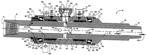
Figure 6 is a sectional view of the assembled top drive swivel 30 of Figure 2.
As can be seen sleeve 150 slides over mandrel 40. Bearings 145,146 rotatably
connect
sleeve 150 to mandrel 40. Bearings 145, 146 are preferably thrust bearings
although
many conventionally available bearing will adequately function, including
conical and
ball bearings. Packing units 305, 415 sealingly connect sleeve 150 to mandrel
40. Inlet
200 of sleeve 150 is and remains fluidly connected to central longitudinal
passage 90
of mandrel 40. Accordingly, while mandrel 40 is being rotated andlor moved up
and
down pumpable substances can enter inlet 200 and exit central longitudinal
passage 90
_g_
CA 02532793 2006-O1-17
WO 2004/022903 PCT/US2003/028341
at lower end 60 of mandrel 40. Recessed area 130 and protruding section 155
form a
peripheral recess between mandrel 40 and sleeve 150. The fluid pathway from
inlet 200
to outlet at lower end 60 of central longitudinal passage 90 is as follows:
entering inlet
200(arrow 201); passing through radial passage 190(arrow 202); passing through
recessed area 130(arrow 202); passing through one of the plurality of radial
inlet ports
140(arrow 202), passing through central longitudinal passage 90(arrow 203);
and
exiting mandrel 40 via lower end 60 at pin connection 80(arrows 204, 205).
Figure 6A shows a blown up schematic view of packing unit 305. Packing unit
305 can comprise packing end 320; packing ring 330, packing ring 340, packing
lubrication ring 350, packing end 360, packing ring 370, packing ring 380,
packing ring
390, packing ring 400, and packing end 410. Packing unit 305 sealing connects
mandrel 40 and sleeve 150. Packing unit 305 can be encased by packing retainer
nut
310 and shoulder 156 of protruding section 155. Packing retainer nut 310 can
be a ring
which threadably engages sleeve 150 at threaded area 316. Packing retainer nut
310 and
shoulder 156 squeeze packing unit 305 to obtain a good seal between mandrel 40
and
sleeve 150. Set screw 315 can be used to lock packing retainer nut 310 in
place and
prevent retainer nut 310 from loosening during operation. Set screw 315 can be
threaded into bore 314 and lock into receiving area 317 on sleeve 150. Packing
unit 415
can be constructed substantially similar to packing unit 305. The materials
for packing
unit 305 and packing unit 415 can be similar.
Packing end 320 is preferably a bronze female packing end. Packing ring 330
is preferably a "Vee" packing ring - - Teflon such as that supplied by CDI
part number
0500700-VS-720 Carbon Reflon (having 2 percent carbon). Packing ring 340 is
preferably a "Vee" packing ring - - Rubber such as that supplied by CDI part
number
0500700-VS-850NBR Aramid. Packing lubrication ring 350 is described below in
the
discussion regarding Figures 6B and 6C. Packing end 360 preferably a bronze
female
packing end. Packing ring 370 is preferably a "Vee" packing ring - - Teflon
such as that
supplied by CDI part number 0500700-VS-720 Carbon Reflon (having 2 percent
caxbon). Packing ring 380 is preferably a "Vee" packing ring - - Rubber such
as that
supplied by CDI part number 0500700-VS-850NBR Aramid. Packing ring 390 is
preferably a "Vee" packing ring - - Teflon such as that supplied by CDI part
number
-9-
CA 02532793 2006-O1-17
WO 2004/022903 PCT/US2003/028341
0500700-VS-720 Carbon Reflon (having 2 percent carbon). Packing ring 400 is
preferably a "Vee" packing ring - - Rubber such as that supplied by CDI part
number
0500700-VS-850NBR Aramid. Packing end 410 is preferably a bronze male packing
zing. Various alternative matexials for packing rings can be used such as
standard
chevron packing rings of standard packing materials. Bronze rings preferably
meet or
exceed an SAE 660 standard.
A packing injection option can be provided for top drive swivel 30. Injection
fitting 225 can be used to inject additional packing material such as teflon
into packing
unit 305. Head 226 for injection fitting 225 can be removed and packing
material can
then be inserting into fitting 225. Head 226 can then be screwed back into
injection
fitting 225 which would push packing material through fitting 225 and into
packing port
220. The material would then be pushed into packing ring 350. Packing ring 350
can
comprise radial port 352 and transverse port 3 51. The material would proceed
through
radial port 352 and exit through transverse port 351. The material would tend
to push
out and squeeze packing rings 340, 330, 320 and packing rings 360, 370, 380,
390, 400
tending to create a better seal between packing unit 305 with mandrel 40 and
sleeve
150. The interaction between injection fitting 235 and packing unit 415 can be
substantially similar to the interaction between injection ftting 225 and
packing unit
305. A conventionally available material which can be used for packing
injection
fittings 225, 235 is DESCO~ 625 Pak part number 6242-12 in the form of a 1
inch by
3/8 inch stick and distributed by Chemola Division of South Coast Products,
Inc.,
Houston, Texas. In Figure 6, injection fitting 235 is shown ninety degrees out
ofphase
and, is preferably located as shown in Figure 9.
Injection fittings 225, 23S have a dual purpose: (a) provide an operator a
visual
indication whether there has been any leakage past either packing units 305,
415 and (b)
allow the operator to easily inject additional packing material and stop seal
leakage
without removing top drive swivel 30 from drill string 20.
Figures 6B and 6C shows top and side views of packing injection ring 350.
Packing injection ring 350 includes a male end 355 at its top and a flat end
356 at its
rear. Ring 350 includes peripheral groove 353 around its perimeter.
Optionally, ring
350 can include inferior groove along its interior. A plurality of transverse
ports 351,
-10-
CA 02532793 2006-O1-17
WO 2004/022903 PCT/US2003/028341
351', 351", 351"', etc. extending from male end 355 to flat end 356 can be
included and
can be evenly spaced along the circumference of ring 350. A plurality of
radial ports
352, 352', 352", 352" ', etc. can be included extending from peripheral groove
353 and
respectively intersecting transverse ports 351, 351', 351", 351"', etc.
Preferably, the
radial ports can extend from peripheral groove 353 through interior groove
354.
Retainer nut 800 can be used to maintain sleeve 150 on mandrel 40. Retainer
nut 800 can threadably engage mandrel 40 at threaded area 801. Set screw 890
can be
used to lock in place retainer nut 800 and prevent nut 800 from loosening
during
operation. Set screw 890 threadably engages retainer nut 800 through bore 900
and sets
in one of a plurality of receiving portions 910 formed in mandrel 40.
Retaining nut
800 can also include grease injection fitting 880 for lubricating bearing 145.
Wiper ring
271 set in area 270 protects against dirt and other items from entering
between the
sleeve 150 and mandrel 40. Grease ring 291 set in area 290 holds in lubricant
for
bearing 145.
Bearing 146 can be lubricated through grease injection fitting 211 and
lubrication port 210. Bearing 145 can be lubricated through grease inj ection
fitting 881
and lubrication port 880.
Figure 7 is a top view of clamp 600 which can be incorporated into top drive
swivel 30. Figure 8 is a side view of clamp 600. Clamp 600 comprises first
portion 610
and second portion 620. First and second portions 610, 620 can be removably
attached
by fasteners 670, 680. Clamp 600 fits in groove 605 of sleeve 150 (Figure 6).
I~ey 700
can be included in keyway 690. A corresponding keyway 691 is included in
sleeve 150
oftop drive swivel 30. Keyways 690, 691 and key 700 prevent clamp 600 from
rotating
relative to sleeve 150. A second key 720 can be installed in keyways 710, 711.
Shackles 650, 660 can be attached to clamp 600 to facilitate handing top drive
swivel
when clamp 600 is attached. Torque arms 630, 640 can be included to allow
attachment of clamp 600 (and sleeve 150) to a stationary part of top drive rig
1 and
prevent sleeve 150 from rotating while drill string 20 is being rotated by top
drive 10
(and top drive swivel 30 is installed in drill string 20). Torque arms 630,
640 are
30 provided with holes for attaching restraining shackles. Restrained torque
arms 630, 640
prevent sleeve 150 from rotating while mandrel 40 is being spun. Otherwise,
frictional
-11-
CA 02532793 2006-O1-17
WO 2004/022903 PCT/US2003/028341
forces between packing units 305, 415 and packing support areas 131, 135 of
rotating
mandrel 40 would tend to also rotate sleeve 150. Clamp 600 is preferably
fabricated
from 4140 heat treated steel being machined to fit around sleeve 150.
Figure 9 is an overall perspective view (and partial sectional view) of top
drive
swivel 30. Sleeve 150 is shown rotatably connected to mandrel 40. Bearings
145,146
allow sleeve 150 to rotate in relation to mandrel 40. Packing units 305, 415
sealingly
connect sleeve 150 to mandrel 40. Retaining nut 800 retains sleeve 150 on
mandrel 40.
Inlet 200 of sleeve 150 is fluidly connected to central longitudinal passage
90 of
mandrel 40. Accordingly, while mandrel 40 is being rotated and/or moved up and
down pumpable substances can enter inlet 200 and exit central longitudinal
passage 90
at lower end 60 of mandrel 40. Recessed area 130 and protruding section 155
form a
peripheral recess between mandrel 40 and sleeve 150. The fluid pathway from
inlet 200
to outlet at lower end 60 of central longitudinal passage 90 is as follows:
entering inlet
200; passing through radial passage 190; passing through recessed area 130;
passing
through one of the plurality of radial inlet ports 40; passing through central
longitudinal
passage 90; and exiting mandrel 40 through central longitudinal passage 90 at
lower end
60 and pin connection 80. In Figure 9, injection fitting 225 is shown ninety
degrees out
of phase and, for protection, is preferably located between inlet 200 and
clamp 600.
Mandrel 40 takes substantially all of the structural load from drill string
20. The
overall length of mandrel 40 is preferably 52 and 5/16 inches. Mandrel 40 can
be
machined from a single continuous piece of heat treated steel bar stock. NC50
is
preferably the API Tool Joint Designation for the box connection 70 and pin
connection
80. Such tool joint designation is equivalent to and interchangeable with 4 %Z
inch IF
(Internally Flush), 5 inch XH (Extra Hole) and 5 '/2 inch DSL (Double Stream
Line)
connections. Additionally, it is preferred that the box connection 70 and pin
connection 80 meet the requirements of API specifications 7 and 7G for new
rotary
shouldered tool joint connections having 6 5/8 inch outer diameter and a 2 3/4
inch
inner diameter. The Strength and Design Formulas of API 7G -Appendix A
provides
the following load carrying specification for mandrel 40 of top drive swivel
30: (a)
1,477 pounds tensile load at the minimum yield stress; (b) 62,000 foot-pounds
torsion
load at the minimum torsional yield stress; and (c) 37,200 foot-pounds
recommended
-12-
CA 02532793 2006-O1-17
WO 2004/022903 PCT/US2003/028341
minimum make up torque. Mandrel 40 can be machined from 4340 heat treated bar
stock.
Sleeve 150 is preferably fabricated from 4140 heat treated round mechanical
tubing having the following properties: (120,000 psi minimum tensile
strength,100,000
psi minimum yield strength, and 2851311 Brinell Hardness Range). The external
diameter of sleeve 150 is preferably about 11 inches. Sleeve 150 preferably
resists high
internal pressures of fluid passing through inlet 200. Preferably top drive
swivel 30
with sleeve 150 will withstand a hydrostatic pressure test of 12,500 psi. At
this pressure
the stress induced in sleeve 150 is preferably only about 24.8 percent of its
material's
yield strength. At a preferable working pressure of 7,500 psi, there is
preferably a 6.7:1
structural safety factor for sleeve 150.
To minimize flow restrictions through top drive swivel 30, large open areas
are
preferred. Preferably each area of interest throughout top drive swivel 30 is
larger than
the inlet service port area 200. Inlet 200 is preferably 3 inches having a
flow area of
4.19 square inches. The flow area of the annular space between sleeve 150 and
mandrel
40 is preferably 20.81 square inches. The flow area through the plurality of
radial inlet
ports 140 is preferably 7.36 square inches. The flow area through central
longitudinal
bore 90 is preferably 5.94 square inches.
The following is a list of reference numerals:
LIST FQR REFERENCE NUMERALS
(Part No.) (Description)
Reference Numeral Description
1 rig
2 crown block
3 cable means
4 travelling block
5 hook
6 gooseneck
7 swivel
-13-
CA 02532793 2006-O1-17
WO 2004/022903 PCT/US2003/028341
8 drilling fluid line
10 top drive unit
11 draw works
12 cable
13 rotary table
14 well bore
15 guide rail
16 support
17 support
18 drill pipe
19 drill string
20 drill string or work string
30 swivel
31 hose
40 swivel mandrel
50 upper end
60 lower end
70 box connection
80 pin connection
90 central longitudinal passage
100 shoulder
101 outer surface of shoulder
102 upper surface of shoulder
110 interior surface
120 external surface (mandrel)
130 recessed area
i 31 packing support area
132 packing support area
140 radial inlet ports (a plurality)
145 bearing (preferably combination
6.875
inch bearing cone, Timken Part number
-14-
CA 02532793 2006-O1-17
WO 2004/022903 PCT/US2003/028341
67786, and 9.75 inch bearing cup bearing
cup, Timken part number 67720)
146 bearing (preferably combination
7 inch
bearing cone, Timken Part number
67791, and 9.75 inch bearing cup
bearing
cup, Timken part number 67720)
150 swivel sleeve
155 protruding section
156 shoulder
157 shoulder
158 packing support area
159 packing support area
160 upper end
170 lower end
180 central longitudinal passage
190 radial passage
200 inlet
201 arrow
202 arrow
203 arrow
204 arrow
205 peripheral groove
206 key way
210 lubrication port
211 grease injection fitting (preferably
grease
zerk (ll4 - 28 td. in. streight,
mat.-monel
Alemite part number 1966-B)
220 packing port
225 injection fitting(preferably packing
injection fitting (10,000 psi) Vesta
- PGI
Manufacturing part number PF 1 ON4-
-15-
CA 02532793 2006-O1-17
WO 2004/022903 PCT/US2003/028341
10)(alternatively Pressure Relief
Tool for
packing injection fitting Vesta -
PGI
Manufacturing part number PRT -PIF
12-20)
226 head
230 packing port
235 injection fitting (preferably packing
injection fitting (10,000 psi) Vesta
- PGI
Manufacturing part number PF 1 ON4-
10)(alternatively Pressure Relief
Tool for
packing injection fitting Vesta -
PGI
Manufacturing part number PRT -PIF
12-20)
240 cover
250 uppershoulder
260 lower shoulder
270 area for wiper ring
271 wiper ring (preferably Parker part
number 959-65)
280 area for wiper ring
281 wiper ring (preferably Parker part
number 959-65)
290 ~ area for grease ring
291 grease ring (preferably Parker part
number 2501000 Standard Polypak)
300 area for grease ring
301 grease ring (preferably Parker part
number 2501000 Standard Polypak)
305 packing unit
310 packing retainer nut
314 bore for set screw
-16-
CA 02532793 2006-O1-17
WO 2004/022903 PCT/US2003/028341
315 set screw for packing retainer
nut
316 threaded area
317 set screw for receiving area
320 packing end
3 3 0 packing ring
340 packing ring
350 packing injection ring
351 transverse port
352 radial port
353 peripheral groove
354 interior groove
3 5 5 male end
356 flat end
360 packing end
370 packing ring
380 packing ring
390 packing ring
400 packing ring
410 packing end
415 packing unit
420 packing retainer nut
425 set screw for packing retainer
nut
430 packing end
440 packing ring
450 packing ring
460 packing lubrication ring
470 packing end
480 packing ring
490 packing ring
500 packing ring
510 packing ring
-17-
CA 02532793 2006-O1-17
WO 2004/022903 PCT/US2003/028341
520 packing end
600 clamp
605 groove
610 first portion
620 second portion
630 torque arm
640 torque arm
650 shackle
660 shackle
670 fastener
680 fastener
690 keyway
691 keyway
700 key
710 keyway
711 keyway
720 key
730 peripheral groove
800 retaining nut
801 threaded area
810 outer surface
820 inclined portion
830 bore
840 inner surface
850 threaded portion
860 upper surface
870 bottom surface
880 lubrication port
8 81 grease inj ection fitting (preferably
grease
zerk (ll4 - 28 td. in. streight,
mat.-monel
Alemite part number 1966-B)
-18-
CA 02532793 2006-O1-17
WO 2004/022903 PCT/US2003/028341
890 set screw
900 bore for set screw
910 receiving portion for set screw
All measurements disclosed herein are at standard temperature and pressure, at
sea level on Earth, unless indicated otherwise. All materials used or intended
to be used
in a human being are biocompatible, unless indicated otherwise.
It will be understood that each of the elements described above, or two or
more
together may also find a useful application in other types of methods
differing from the
type described above. Without further analysis, the foregoing will so fully
reveal the
gist of the present invention that others can, by applying current knowledge,
readily
adapt it for various applications without omitting features that, from the
standpoint of
prior art, fairly constitute essential characteristics of the generic or
specific aspects of
this invention set forth in the appended claims. The foregoing embodiments are
presented by way of example only; the scope of the present invention is to be
limited
only by the following claims.
-19-