Note: Descriptions are shown in the official language in which they were submitted.
CA 02532911 2007-08-10
1
TITLE OF THE INVENTION
Drill Bit
FlELD OF THE INVENTION
[D001] The present invention relates to the general field of dri[ling,
and is particularly concemed with a driH bit.
BAGKGR(4UNU OF THE INVENTION
[000ZJ in the geological exptoration, mining and construction
industries, among others, drin bits are used to drM through rock, concrete and
other materials. Typically, these bits Include a crown made of a mixture of
metal and diamonds. This crown is the por8on of the bit that erodes the
material through which a bore is drilled
[0003] Some bits Indude a cermal passageway through which water
is injected. To let water and debris flow out of the drill's way, the crown
typically indudes a plurality of segments separated by openings.
[0004] The crown material used to manutaoture the crowns of the
bits is typically substant'rally harder than the material through which
drilling is
perPormed. However, this crown material Is typically nufatively brittle_
AcCordingly, the dimensions of the openings between the segments in the
crown are fimited by the brittleness of the material used to manufacture these
crowns.
CA 02532911 2006-01-16
2
[0005] Indeed, if these openings extend too deep within the crown,
there is a risk that a segment will be broken while drilling. In this case,
there is
a need to remove the bit from the drilling apparatus and to use a new bit.
[0006] Since these drill bits are relatively expensive, the size of the
segments are typically limited in currently existing bits, as shallower
openings
between the segments render the latter typically less prone to being ruptured
or
otherwise damaged. This shallowness of openings is a desired characteristic
as breaking a segment typically means that the whole bit must be discarded. In
addition, the time required to remove the drill bit and to position the new
bit
inside the bore that was being bored is typically relatively long as the bit
and
drilling apparatus need to be removed entirely from this bore in order to
replace
the damaged bit
[0007] However, bits including relatively shallow openings will be
wom from drilling in a relatively short amount of time. Therefore, once more,
there is a need to take time to remove the bit from the bore to drill at
relatively
short time intervals to replace the worn out drill bit.
[0008] US Patent Serial Number 5,316,416 issued on May 31, 1994
to Kim describes a drill bit that attempts to alleviate this disadvantage of
previously known drill bits. In this patent, a drill bit including a tool body
having
an open upper end and an annular diamond blade portion is described. The
diamond blade portion includes an upper circumferential edge and a lower
circumferential edge, the diamond blade portion being attached at the lower
circumferential edge to the open upper end of the tool body. A plurality of
upper
cuts each extends downwardly from the upper circumferential edge of the
diamond blade portion. The upper cuts terminate at a depth of the diamond
blade portion above the lower circumferential edge. A plurality of lower slots
each extends upwardly from the lower circumferential edge of the diamond
CA 02532911 2006-01-16
3
blade portion and terminate at a height below the upper circumferential edge.
The lower slots are positioned under and between the upper cuts and extend
higher than the bottom of the upper cuts.
[0009] However, the configuration of this drill bit is not suitable for
use in wet drilling wherein water is injected inside the drill bit during the
drilling
process. Indeed, the configuration of the cuts in this drill bit does not
allow the
water to flow radially outwardly towards the outside of the drill bit as no
longitudinal passageways are present that would allow the water to move away
from the crown of the drill bit after it exits the crown.
[0010] Another problem that sometimes occurs in prior art drill bit is
that the drilling process may produce a radially uneven abrasion of the crown.
In cases wherein this phenomenon occurs, the efficiency of the drilling
process
is reduced relatively to cases wherein the crown is abraded substantially
uniformly.
[0011] Against this background, there exists a need in the industry to
provide an improved drill bit.
OBJECT OF THE INVENTION
[0012] An object of the present invention is therefore to provide an
improved driil bit.
SUMMARY OF THE INVENTION
[0013] In a broad aspect, the invention provides a bit for drilling a
hole. The bit includes:
CA 02532911 2006-01-16
4
[0014] - a support member, the support member defining a support
member proximal end and a substantially longitudinally opposed support
member distal end, the support member having a passageway extending
substantially longitudinally therethrough;
[0015] - a substantially annular crown defining a crown distal end
and an opposed crown proximal end, a radially inwardly located crown inner
surface and a radially outwardly located crown outer surface, a crown inner
diameter and a crown outer diameter, the crown extending from the support
member such that the crown proximal end is located substantially adjacent the
support member distal end;
[0016] - a slot extending between the crown inner and outer
surfaces from the crown distal end substantially longitudinally towards the
crown proximal end, the slot defining a slot first side wall, a substantially
circumferentially opposed slot second side wall and a slot proximal wall
extending therebetween substantially opposed the crown distal end; and
[0017] - a reinforcing member extending substantially
circumferentially across the slot between the slot first and second walls;
[0018] - wherein the slot indudes a slot proximal segment
extending between the reinforcing member and the slot proximal wall and a slot
distal segment extending between the reinforcing member and the crown distal
end.
[0019] In a variant, the bit indudes a plurality of slots each having a
reinforcing member extending substantially circumferentially thereacross. The
slots define a plurality of drilling segments, the reinforcing members
CA 02532911 2006-01-16
interconnecting the segments.
[0020] Advantageously, the reinforcing members increase the
robustness of the segments. Accordingly, such segments can extend
longitudinally away from the support over a greater distance than in drill
bits
wherein reinforcing members are not provided. These segments are relatively
less prone to failure than non-reinforced segments and allow to manufacture
drill bits having a relatively longer useful life because of the presence of
the
reinforcing members.
[0021] In addition, in some embodiments of the invention, the
reinforcing members allow to correct an uneven abrasion of the segments.
[0022] The bit is relatively easy to manufacture and is typically
compatible with existing drilling equipments and methods. In some
embodiments of the invention, the manufacturing method used to manufacture
the crown causes deviations in the shape of the crown from a perfectly annular
shape to be relatively small.
[0023] In another broad aspect, the invention provides a bit for
drilling a hole. The bit includes:
[0024] - a support member, the support member defining a support
member proximal end and a substantially longitudinally opposed support
member distal end, the support member having a passageway extending
substantially longitudinally therethrough;
[0025] - a substantially annular crown defining a crown distal end
and an opposed crown proximal end, a radially inwardly located crown inner
CA 02532911 2006-01-16
6
surface and a radially outwardly located crown outer surface, a crown inner
diameter and a crown outer diameter, the crown having a crown radial
thickness equal to a difference between the crown outer and inner diameters,
the crown extending from the support member such that the crown proximal
end is located substantially adjacent the support member distal end;
[0026] - a slot extending between the crown inner and outer
surfaces from the crown distal end substantially longitudinally towards the
crown proximal end, the slot defining a slot first side wall, a substantially
circumferentially opposed slot second side wall and a slot proximal wall
extending therebetween substantially opposed the crown distal end; and
[0027] - a reinforcing member extending substantially
circumferentially across the slot between the slot first and second walls, the
reinforcing member extending substantially radially within the slot over a
reinforcing member radial extension, the reinforcing member radial extension
being substantially smaller than the crown radial thickness.
[0028] Other objects, advantages and features of the present
invention will become more apparent upon reading of the following non-
restrictive description of preferred embodiments thereof, given by way of
example only with reference to the accompanying drawings.
BRIEF DESCRIPTION OF THE DRAWINGS
[0029] In the appended drawings:
[0030] Figure 1, in a perspective view, illustrates a bit for drilling a
hole in accordance with an embodiment of the present invention;
CA 02532911 2006-01-16
7
[0031] Figure 2, in a top elevation view, illustrates the bit of Figure 1;
[0032] Figure 3, in a partial side cross-sectional view along the line
III-III of Figure 2, illustrates the bit of Figure 1;
[0033] Figure 4A, in a partial side cross-sectional view along the line
III-III of Figure 2, illustrates a stage in the wearing out of the bit of
Figure 1;
[0034] Figure 413, in a partial side cross-sectional view along the line
Iii-ill of Figure 2, illustrates another stage in the wearing out of the bit
of Figure
1;
[0035] Figure 4C, in a partial side cross-sectional view along the line
III-III of Figure 2, illustrates yet another stage in the wearing out of the
bit of
Figure 1;
[0036] Figure 4D, in a partial side cross-sectional view along the line
III-III of Figure 2, illustrates yet another stage in the wearing out of the
bit of
Figure 1;
[0037] Figure 5A, in a partial side cross-sectional view along the line
III-III of Figure 2, illustrates the bit of Figure 1;
[0038] Figure 513, in a side cross-sectional view, illustrates the detail
VB of the drill bit of Figure 5A;
[0039] Figure 5C, in a side cross-sectional view, illustrates a region
corresponding to the detail VB in a bit in accordance with an altemative
embodiment of the present invention having altemative reinforcing members
CA 02532911 2006-01-16
8
extending within slots of a crown of the drill bit;
[0040] Figure 5D, in a side cross-sectional view, illustrates a region
corresponding to the detail VB in a bit in accordance with another alternative
embodiment of the present invention having other altemative reinforcing
members extending within slots of a crown of the drill bit;
[0041] Figure 5E, in a side cross-sectional view, illustrates a region
corresponding to the detail VB in a bit in accordance with yet another
alternative embodiment of the present invention having yet other alternative
reinforcing members extending within slots of a crown of the drill bit;
[0042] Figure 5F, in a side cross-sectional view, illustrates a region
corresponding to the detail VB in a bit in accordance with yet another
alternative embodiment of the present invention having yet other alternative
reinforcing members extending within slots of a crown of the drill bit;
[0043] Figure 5G, in a side cross-sectional view, illustrates a region
corresponding to the detail VB in a bit in accordance with yet another
alternative embodiment of the present invention having yet other alternative
reinforcing members extending within slots of a crown of the drill bit;
[0044] Figure 5H, in a side cross-sectional view, illustrates a region
corresponding to the detail VB in a bit in accordance with yet another
alternative embodiment of the present invention having yet other alternative
reinforcing members extending within slots of a crown of the drill bit;
[0045] Figure 6A, in a top elevation view, illustrates a bit in
accordance with an altemative embodiment of the present invention having
CA 02532911 2006-01-16
9
alternatively shaped slots formed into a crown of the drill bit;
[0046] Figure 6B, in a top elevation view, illustrates a bit in
accordanoe with another alternative embodiment of the present invention
having other alternatively shaped slots formed into a crown of the drill bit;
and
[0047] Figure 6C, in a top elevation view, illustrates a bit in
accordance with yet another an altemative embodiment of the present
invention having yet other alternatively shaped slots formed into a crown of
the
drill bit.
DETAILED DESCRIPTION
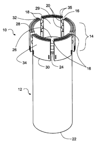
[0048] Figure 1 illustrates a bit 10 for drilling a hole (not shown in the
drawings). The bit 10 includes a support member 12 and a crown 14 extending
from the support member 12. A plurality of slots 16 is formed into the crown
14
and defines a plurality of drilling segments 18. The bit 10 further includes a
plurality of reinforcing members 20, each reinforcing member 20 extending
between adjacent segments 18.
[0049] The reinforcing members 20 improve the structural integrity of
the crown 14. Therefore, the crown 14 may extend longitudinally from the
support member 12 over a distance that is larger than distances that would be
achievable using prior art crown configurations.
[0050] Although the crown 14 shown in the drawings includes 5
slots, it is within the scope of the invention to have crowns that include
fewer or
more slots. Furthermore, in some embodiments of the invention, only one slot
is formed into a crown of a bit.
CA 02532911 2006-01-16
[0051] The support member 12 defines a support member proximal
end 22 and a substantially longitudinally opposed support member distal end
24. The support member 12 has a passageway 26 extending substantially
longitudinally therethrough. In some embodiments of the invention, the support
member 12 is substantially tubular and cylindrical. In these embodiments, the
support member 12 defines support member intemal and external diameters.
[0052] The crown 14 is substantially annular and defines a crown
distal end 28 and an opposed crown proximal end 30, a crown distal surface 29
at the crown distal end 28, a radially inwardly located crown inner surface 32
and a radially outwardly located crown outer surface 34, a crown inner
diameter
and a crown outer diameter. The crown 14 has a crown radial thickness equal
to a difference between the crown outer and inner diameters. The crown 14
extends from the support member 12 such that the crown proximal end 30 is
located substantially adjacent the support member distal end 24.
[0053] The crown inner and outer surfaces 32 and 34 are
substantially cylindrical. However, in altemative embodiments of the
invention,
the crown inner and outer surfaces 32 and 34 have any other suitable shape.
[0054] In some embodiments of the invention, the crown distal
surface 29 is substantially perpendicular to the crown inner and outer
surfaces
32 and 34. Also, while not necessarily present in all embodiments of the
invention, two substantially annular circumferential grooves 35 are formed
into
the crown distal surface 29. The grooves 35 have a substantially V-shaped
cross-section.
[0055] In some embodiments of the invention, as better seen from
Figures 2 and 3, the crown outer diameter is substantially larger than the
support member outer diameter and the crown inner diameter is substantially
CA 02532911 2006-01-16
11
smaller than the support member inner diameter. In these embodiments, the
slots 16 allow the passage of water from the passageway 26, into the slots 16
and outside of the support member 12. However, in other embodiments of the
invention no water is used for drilling and the crown 14 may then have radial
dimensions substantially similar to the radial dimensions of the support
member
12.
[0056] The slots 16 extend between the crown inner and outer
surfaces 32 and 34 from the crown distal end 28 substantially longitudinally
towards the crown proximal end 30. As better seen in Figure 2, the slots 16
define a slot first side wall 36, a substantially circumferentially opposed
slot
second side wall 38 and a slot proximal wall 40 extending therebetween
substantially opposed the crown distal end 28. The first and second slot side
walls 36 and 38 extend substantially radially. In some embodiments of the
invention, the slot proximal wall 40 is defined by the support member 12.
However, in other embodiments of the invention, the slot proximal wall 40 is
formed by the crown 14 (not shown in the drawings).
[0057] Referring to Figure 2, in some embodiments of the invention,
the reinforcing members 20 extend substantially circumferentially across the
slots 16 between the slot first and second walls 36 and 38. One, two or more
reinforcing members 20 extend across at least some of the slots 16. For
example, Figure 3 shows an embodiment of the invention wherein two
reinforcing members 20 are substantially longitudinally spaced apart relative
to
each other within each slot 16. Figure 5E shows an embodiment of the
invention wherein two reinforcing members 20e are substantially radially
spaced apart relative to each other within each slot 16. Figures 5D, 5F, 5G
and
5H show embodiments of the invention wherein only one reinforcing member
20d, 20f, 20g and 20h extends within each slot 16.
CA 02532911 2006-01-16
12
[0058] The reinforcing members 20 are substantially cylindrical.
However, as described in further details hereinbelow, the reinforcing members
20 may have other suitable shapes.
[0059] As seen on Figure 3, in some embodiments of the invention,
the reinforcing members 20 are spaced apart from the slot bottom wall 40 and
from the crown distal end 28. In these embodiments, the slots 16 each include
a slot proximal segment 42 extending between the reinforcing member 20 and
the slot proximal wall 40 and a slot distal segment 44 extending between the
reinforcing member 20 and the crown distal end 28. The reader skilled in the
art
will readily appreciate that the slot distal and proximal segments 44 and 42
have been defined with respect with one of the reinforcing members 20
extending across one of the slots 16. However, slot segments may be defined
relatively to other reinforcing member 20 extending across this slot 16.
[0060] The reinforcing members 20 extend substantially radially
within each slot 16 over a reinforcing member radial extension, the
reinforcing
member radial extension being substantially smaller than the crown radial
thickness. Typically, the reinforcing member radial extension is from about 1
percent to about 90 percents of the crown radial thickness.
[0061] Indeed, if the reinforcing members 20 had a reinforcing
member radial extension substantially equal to the crown radial thickness,
there
would be a moment during the wearing out of the crown 14 at which the whole
circumference of the crown 14 would be in contact with the material through
which a hole is drilled. Typically, this situation would result in relatively
inefficient drilling.
[0062] In some embodiments of the invention, the reinforcing
member radial extension is selected such that it is as small as possible while
CA 02532911 2006-01-16
13
providing a suitable degree of reinforcement of the crown 14. For example, and
non-limitingly, it has been found that reinforcing member radial extensions of
from about 20 percents to about 50 percents of the crown radial thickness
produce good results. In terms of absolute dimensions, and non-limitingly, it
has been found that reinforcing member radial extensions of from about 1.5
mm to about 5 mm produce good results.
[0063] In some embodiments the reinforcing member longitudinal
dimension must be sufficiently small to allow water and drilling debris to
flow
radially within the slots 16 at a sufficient rate. For example, and non-
limitingly, it
has been found that reinforcing members 20 extending substantially
longitudinally within the slots 16 over a reinforcing member longitudinal
dimension smaller than about 25 percent of a distance between the crown
distal end 28 and the slot proximal wall 40 produce good results in operation.
[0064] Typically, the bit 10 is manufactured using graphite molds.
For example, such a mold is substantially annular. 1NWithin the mold, inserts
are
provided at locations corresponding to the slotsl6. Then, a mixture of metal
and diamonds in a powder form is inserted within the mold and pressure is
applied onto the mixture to squeeze the particles fonning the powder together.
[0065] After the powder has been tightened, the segments are
infiltrated with a compatible brazing alloy at a predetermined temperature.
This
infiltration process confers solidity to the crown 14, as the brazing alloy
acts as
a binder for the metal and diamonds particles. In addition, the brazing alloy
also
reinforces a link between the crown 14 and the support member 12.
[0066] The reinForcing members 20 are formed by using inserts
shaped substantially similarly to the slots 16, each insert including one or
more
bores having a shape substanfia11y simitar'to~heshape nf a"
CA 02532911 2006-01-16
14
20. Then, when pressure is applied onto the powder, the mixture of diamonds
and metal flows into the bores and forms the reinforcing members 20.
[0067] In an altemative embodiment of the invention, the bores of
the inserts are filled with the mixture that forms the reinforcing members 20.
Then, filling the sections of the molds corresponding to the segments 18
produces the crown 14.
[0068] In yet another manner of manufacturing the bit 10, the
segments 18 are manufactured separately and simply positioned within a mold
with inserts including the reinforcing members 20. Subsequently, the powder is
squeezed and brazing is performed as described hereinabove.
[0069] In yet another manner of manufacturing the bit 10, the
segments 18 and the reinforcing members 20 are manufactured separately.
The reinforcing members 20 are either manufactured using the same materials
as those used in manufacturing the segments 14, or they are simply
manufactured using a metal. Thereafter, the reinforcing members 20 are
brazed, welded, soldered or otherwise secured to the segments 18.
[0070] Other steps performed in manufacturing the bit 10 are well
known in the art and will therefore not be described in further details.
[0071] In addition to diamonds dispersed in a metal matrix, the
crown 14 may be manufactured using any other suitable abrasive dispersed in
a suitable matrix. For example, so-called artificial diamonds might be used.
Also, in some embodiments of the invention, the matrix inGudes a composite
material, such as for example carbon fibers in a suitable resin.
CA 02532911 2006-01-16
[0072] In use, the bit 10 is inserted at the end of a drilling apparatus
and used to drill through rock, concrete or any other material. If required,
water
is forced through the passageway 26. The water lubricates the contact
between the bit 10 and the material being drilled and carries the debris
produced by the drilling process away from the bit 10. To that effect, the at
least part of the debris and the water passes through the slots16.
[0073] The reinforcing members 20 improve the solidity of the drill bit
10. When the bit 10 is used, the segments 18 are progressively worn. When
the segments 18 are wom up to a point wherein the crown distal surface 29
reaches the reinforcing members 18, the reinforcing members 18 are eroded
along with the segments 18.
[0074] After the reinforcing members 20 have been worn out, the
segments 18 extend away from the support member 12 over a distance small
enough that the risk of breaking the segments 18 by the drilling process is
significantly reduced.
[0075] In a specific example of implementation, it was possible to
manufacture bits similar to the bit 10 with slots 16 that were 16 mm deep.
These bit were at least as strong and at least as resistant to accidental
damage
to the segments 18 as a bit that did not indude reinforcing members 20 but
that
had slots of a depth of only 12 mm.
[0076] Figures 4A to 4D illustrate an example of wearing out of the
bit 10 wherein uneven wear is produces. In Figure 4A, the bit 10 has not been
used. After some use, as seen in Figure 4B, the bit 10 is worn out so that a
crown distal surface 29b is convex between the crown inner and outer surfaces
32 and 34. This convex shape is undesirable as it affects the drilling
performance of the bit 10.
CA 02532911 2006-01-16
16
[0077] It has been observed that when the crown distal surface 29b
reaches the reinforcing member 20, further use of the drill accelerates the
wear
of the portion of the crown 14 located at the radial location of the
reinforcing
member 20. After the reinforcing member has been abraded, a crown distal
surface 29c is convex between the crown inner and outer surfaces 32 and 34,
as seen in Figure 4C. Further use of the bit 10 results in an increase in wear
adjacent the crown inner and outer surfaces 32 and 34, which produces a
substantially flat crown distal surface 29d, as seen in Figure 4D.
[0078] It is hypothesized that this evening out of the wear of the
crown in a radial direction is produced by an increase in the heat produced in
the crown by the reinforcing member 20. However, other mechanisms may be
involved in the production of this result.
[0079] Figures 5C through 5H illustrate the cross-section of
alternative reinforcing members 20c through 20h. The reinforcing members
20c through 20h are all substantially elongated and of substantially uniform
cross-section.
[0080] The reinforcing members 20c are of a substantially
rectangular cross-section. The reinforcing members 20f are of a substantially
square cross-section. The reinforcing members 20d are substantially plate-
shaped and extend at an angle relatively to a longitudinal axis of the bit 10.
The reinforcing members 20e are substantially plate-shaped and extend
substantially longitudinally. The reinforcing members 20h are of a
substantially
star-shaped cross-section.
[0081] The reader skilled in the art will readily appreciate that the
examples of reinforcing members 20 and 20c through 20h are only examples
and that many other suitable reinforcing members ~ar-e -wnthin-1he :soope
vf,#he
CA 02532911 2006-01-16
17
invention. For example, reinforcing members having attemative uniform cross-
sections and reinforcing members having non-uniform cross-sections are also
within the scope of the invention.
[0082] Figures 6A, 6B and 6C illustrate altemative slots 16a, 16b
and 16c and atternative segments 18a, 18b and 18c of altemative bits 10a, 10b
and 10c. The slots 16a do not extend perfectly radially. Instead, the slots
16a
are angled relatively to radiuses of the bit. The slots 16b are similar to the
slots
16. The slots 16c are tapered in a radially outwardly directed orientation.
[0083] The segments 18a have a shape different than the segments
18 because of difference in shape between the slots 16 and 16a. The
segments 18b and 18c each have a radially outwardly located outer groove 19
and 19' formed longitudinally thereinto.
[0084] The illustrated slot and segments shapes shown in Figures
6A, 6B and 6C are well-known in the art and will therefore not be described in
further details. Also, the segments and slots may take any other altemative
shapes in altemative embodiments of the invention.
[0085] Although the present invention has been described
hereinabove by way of preferred embodiments thereof, it can be modified,
without departing from the spirit and nature of the subject invention as
defined
in the appended claims.