Note: Descriptions are shown in the official language in which they were submitted.
CA 02533093 2006-01-19
WO 2005/013749 PCT/EP2004/007551
DESCRIPTION
SELF-TAPPING STUD FOR RUBBER SUPPORTS OF SHOES, TYRES
AND THE LIKE, AND A TOOL FOR MOUNTING SAID STUD
TECHNICAL FIELD
The present invention relates to a self-tapping stud for rubber supports of
shoes, tyres and the like, and to a tool for mounting said stud.
PRIOR ART
Studs of the stated type are often used to ensure correct gripping of shoes
or tyres under conditions of poor adherence (for example on snow) or, in
to other cases, to limit shoe sole wear (for example in certain motorcycle
competitions in which equilibrium is maintained with the aid of the feet).
Studs of this type currently exist comprising a body provided with a
threaded portion to be connected to a rubber support (for example a shoe
sole or a tyre) and, at its opposite end, a head of particularly hard material
to ensure that the shoe or tyre grips the ground or to protect the sole
against wear.
The threaded portion of said studs presents a cylindrical core from which
a thread projects with its free helical edge contained substantially within a
conical surface converging towards the free end of the thread (to facilitate
its insertion into the rubber). Hence in practice the thread and core are
similar to those of self-tapping wood screws.
In addition the free end of the thread (that which enters first into the
rubber support when the stud is applied) presents in some cases a small
cutting edge positioned substantially in a direction perpendicular to a core
axis.
This stud is applied to rubber supports by a tool comprising two mutually
CA 02533093 2006-01-19
WO 2005/013749 PCT/EP2004/007551
2
communicating seats, the more inner seat receiving the head of the stud
and the more outer its body; for its insertion, the stud is mounted on the
tool with the threaded portion projecting, and is screwed into the support
such that during its screwing, the stud leaves the seats naturally and
remains locked in the support.
However, traditional studs and tools present numerous drawbacks, of
which the most serious has proved to be the poor engagement between
the traditional stud and the support, requiring threaded portions of very
large dimensions to ensure good retention of the stud in the support. For
1o the same reason (poor engagement), traditional studs are able to bend,
escape and sometimes tear the rubber.
This is evidently damaging, both because considerable support
thicknesses are required, and because even when very thick supports are
available, very deep insertion of an extraneous component such as the
stud causes problems in the overall support structure and possible
damage to the support surface.
Traditional tools are also problematic as in many cases they do not enable
studs to be correctly applied to a rubber support.
In this respect, the depth of the tool seat and the height of the stud head
have to be calculated to achieve optimum positioning of the body within
the rubber support. The stud should self-release naturally.
However because of the friction between the contacting surfaces, the stud
often does not automatically leave the seats in which it is housed but,
because of rotation, the threaded part tears the rubber from the support,
leaving the support surface damaged and the stud badly positioned.
CA 02533093 2011-05-17
3
DISCLOSURE OF THE INVENTION
The technical aim of the present invention is therefore to provide a self-
tapping stud for rubber supports of shoes, tyres and the like, and a tool for
mounting said stud, by which the stated technical drawbacks of the known
art are overcome.
Within the framework of this technical aim an object of the' invention is to
provide a stud which grips the rubber support in an optimum manner even
if the threaded portions are of small dimensions (in the longitudinal
direction, i.e. along the axis of the stud core).
According to the present invention, there is provided a self-tapping stud for
rubber
supports, comprising a body presenting a threaded portion fixable into said
rubber
support and a head which projects from said support when said stud has been
mounted, characterised in that said threaded portion presents a thread having
a
given inclination and being provided with a free helical edge which extends
along a
substantially cylindrical surface; in that said threaded portion presents a
core which
is substantially conical or frusto-conical having sloped sides for a length of
said
threaded portion; and in that said threaded portion presents a thread provided
at its
free start with a cutting edge, said cutting edge being orientated with the
same
inclination as said thread.
In this manner the stud of the invention does not escape, does not bend,
and can project from the rubber support to. a sufficiently large extent,
depending on requirements.
Another object of the invention is to provide a stud which can be applied to
the rubber support without causing problems to the support structure or
CA 02533093 2011-05-17
3a
damage to its surface.
A further object of the invention is to provide a mounting tool for said stud
which enables the stud to be applied in an extremely reliable manner, with
a very low risk of tearing rubber portions of the support.
The technical aim together with these and further objects are attained
according to the present invention by a self-tapping stud for rubber
supports of shoes, tyres and the like together with a mounting tool for said
stud, in accordance with the accompanying claims.
BRIEF DESCRIPTION OF THE DRAWINGS
Further characteristics and the advantages of the invention will be more
apparent from the description of a preferred but non-exclusive
embodiment of the self-tapping stud for rubber supports of shoes, tyres
CA 02533093 2006-01-19
WO 2005/013749 PCT/EP2004/007551
4
and the like, and the tool for mounting said stud, illustrated by way of non-
limiting example in the accompanying drawings, in which:
Figure 1 is front elevation of a stud according to the invention, inserted
into a rubber support such as a shoe sole or a tyre;
Figure 2 is a longitudinal section (through one half) of the stud of the
invention;
Figure 3 is an exploded view of a first embodiment of a tool for applying
the studs of the invention;
Figure 4 shows the tool of Figure 3 in a first operative configuration
1o particularly for stud mounting;
Figure 5 shows the tool of Figure 3 in a second operative configuration,
particularly suitable for stud removal;
Figure 6 is a view in partial section of a second embodiment of a stud
application and removal tool according to the invention;
Figure 7 is a view in partial section of a third embodiment of a stud
application and removal tool;
Figure 8 is a plan view of the stud body part in another embodiment;
Figure 9 is a view in partial section of a tool particularly suitable for
mounting or removing the stud of Figure 8; and
Figures 10-12 show other embodiments of the stud according to the
invention.
BEST MODE FOR CARRYING OUT THE INVENTION
Said figures show a self-tapping stud for rubber supports of shoes, tyres
and the like indicated overall by the reference numeral 1.
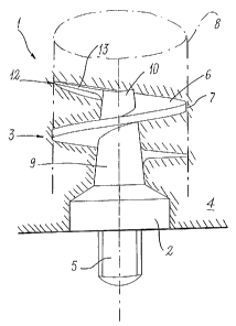
The stud 1 comprises a body 2 presenting a threaded portion 3 lockable
into the rubber support 4 (the stud 1 is shown locked into the support 4 in
CA 02533093 2006-01-19
WO 2005/013749 PCT/EP2004/007551
Figure 1) and a head 5 which projects from the support 4 when the stud is
mounted.
Advantageously the threaded portion 3 presents a thread 6 provided with
a free helical edge 7 which extends along a substantially cylindrical
5 surface 8.
The threaded portion 3 also presents a substantially conical or frusto-
conical core 9, with its converging end 10 disposed towards the free end
of the core 9.
Advantageously the thread 6 of the threaded portion 3 is provided at its
1o free start 12 with a cutting edge 13, which is orientated with the same
inclination as the thread and could reach the centre of the core.
In this manner the thread 6 presents a good capacity for penetration and
retention within the support 4 along its entire length.
Preferably, as shown in the accompanying figures and in particular in
1s Figure 2, a first thread profile 15 facing the convergent end 10 of the
core
9 is substantially perpendicular to an axis 16 of the core 9, while a second
thread profile 17 facing the body 2 of the core 9 is substantially inclined to
the axis 16 of the core 9; preferably the second profile 17 is inclined at an
obtuse angle of between 95 and 110 degrees to the axis of said core,
20 depending on the rubber mix.
In addition, the free helical edge 7 presents a substantially flat
longitudinal
profile having dimensions between 0.4 and 1.6 millimetres based on the
stud dimensions.
For example, for a rally tyre rubber, which is known to be very soft, the
25 angle between the second profile 17 and the core axis is approximately
CA 02533093 2011-05-17
6
95 and the longitudinal profile of the free helical edge 7 presents a length
of approximately 1.6 millimetres.
The present invention also relates to a mounting tool for studs of the
stated type, the tool being indicated overall by the reference numeral 20.
In a first embodiment of the tool, shown in Figures 3, 4, 5, the tool 20
comprises a seat 21 to receive as an exact fit the head 5 of the stud 1
and/or the body 2 if this is faceted (in the form of an ellipse 3A or having a
notch 4A at its end) and an abutment surface 22 adjacent to the mouth 23
of the seat 21, so that the tool 20 enables the stud 1 to be screwed into
the support 4 such that the abutment surface 4 abuts against the support
4, an indication that the stud is completely mounted being given when the
surface of the first element 24 abuts against the surface of the second
element 25.
The tool 20 also comprises a body 24, 25 in which an operating element
26 is slidable, carrying at its end the seat 21,
The body presents a first element 24 and a second element 25 which are
slidable one in the other against and by the action of elastic means 27
such that the body can assume a first extended position (in which as
shown in Figure 4 the element 24 and the element 25 are spaced apart
from each other longitudinally), in which the first element 24 defines a
widened chamber 28 facing the seat 21 of the operating element 26, to
receive as an exact fit at least a part of the body 2 of the stud 1, and a
CA 02533093 2011-05-17
6a
second contracted position (in which as shown in Figure 5 the element 24
and element 25 are inserted longitudinal one into the other until they
mutually abut), in which the seat 21 of the operating element 26 projects from
the
first element 24.
CA 02533093 2006-01-19
WO 2005/013749 PCT/EP2004/007551
7
The seat also preferably comprises magnetic means 29 such as a magnet
to retain the stud 1 in the seat during mounting and removal.
The tool of the first embodiment enables studs to be both applied and
extracted; specifically, in the configuration shown in Figure 4 the tool is
particularly suitable for applying studs, whereas in that of Figure 5 it is
particularly suitable for extracting them.
In a second embodiment of the tool of the invention, shown by way of
example in Figure 6, the tool 20 comprises a body 24 from which the seat
21 projects.
to Magnetic means in the form of a magnet 29 are again provided in this
case.
This embodiment of the tool 20 of the invention is suitable both for
mounting studs 1 and for extracting them.
In a third embodiment of the tool, shown by way of example in Figure 7,
the tool 20 comprises the body 24 from which the seat 21 projects, the
body 24 presenting close to said seat an end portion 31 which converges
to facilitate visibility in the seat region.
This embodiment of the tool is particularly suitable for removing studs 1,
as it provides high visibility in the seat region; the tool can evidently also
be used for mounting.
In all the described embodiments, the tool 20 presents a faceted shank 32
for its connection to an electric screwdriver or drill, enabling the studs to
be applied easily and quickly; in other examples the tool can be used with
a manual handgrip.
In a further embodiment shown in Figure 8, the stud has its body 2
elliptically faceted at 3A and notched at 2a, with the head 5 presenting
CA 02533093 2006-01-19
WO 2005/013749 PCT/EP2004/007551
8
rounded or round profiles. Correspondingly the mounting and/or removal
tool 20 presents a very wide seat 21 for receiving the faceted portions of
the body. Adjacent to the seat 21 this tool carries the retention magnet
29.
The operation of the self-tapping stud for rubber supports of shoes, tyres
and the like and of the mounting tool for said stud according to the
invention are apparent from that described and illustrated, and is
substantially as follows.
With reference to the first embodiment of the tool 20, mounting is
to achieved by setting the tool in the configuration shown in Figure 4,
enabling it to correctly receive the stud 1.
The stud 1 is then inserted by inserting its head 5 into the seat 21 and its
body 2 at least partially into the wide chamber 28 (the body 2 is preferably
completely housed in the wide chamber 28).
At this point the threaded portion 3 of the stud 1 can be rested against the
surface of the rubber support 4 and, by exerting pressure, be screwed into
said support.
Insertion is very simple because the cutting edge 13 has the same
inclination as the thread and the thread presents large longitudinal
dimensions (pitch), the connection obtained being very secure because of
the large surface of the thread 6 which is obtained by making the free
edge of the thread 6 with an obtuse angle along the cylindrical surface 8
and by making the core 9 cylindrical to increase the dimensions of the
thread for gripping along the free portion of the stud 1.
The stud is extracted with the tool of Figures 3-5 by firstly setting the tool
in the configuration of Figure 5; the head of the stud 1 (which projects
CA 02533093 2006-01-19
WO 2005/013749 PCT/EP2004/007551
9
from the support) is then inserted into the seat 21 and the tool rotated to
unscrew the stud.
When the tool is changed over from one configuration to another, it is
locked by a setscrew 30.
The magnet 29 enables the stud to be retained within the seat 21, 28 until
it has been brought into contact with and properly positioned on the
support.
The second embodiment of the tool is used by inserting the head 5 of the
stud 1 into the seat 21 of the tool 20 and then rotating the tool 20 while
to pressing it against the surface of the support to screw in the stud 1 (the
stud is mounted when the surface 22 abuts against the support 4).
This tool can also be used for unscrewing, although for this function the
third embodiment of the tool 20 is particularly suitable.
The third embodiment of the tool is particularly suitable for unscrewing
because it provides excellent visibility around the seat 21, enabling the
head 5 of the stud 1 projecting from the support to be easily and quickly
inserted therein; it can also be used for screwing and hence for mounting
studs in the rubber support.
When the tool has been mounted on the head it merely needs to be
rotated to unscrew the stud.
It has been found in practice that the self-tapping stud for rubber supports
of shoes, tyres and the like and the tool for mounting said stud of the
invention are particularly advantageous because studs can be very
securely fixed into a rubber support without damaging the support.
The self-tapping stud for rubber supports of shoes, tyres and the like and
the tool for mounting said stud conceived in this manner are susceptible to
CA 02533093 2006-01-19
WO 2005/013749 PCT/EP2004/007551
numerous modifications and variants, all falling within the scope of the
inventive concept; moreover all details can be replaced by technically
equivalent elements.
In practice the materials used and the dimensions can be chosen at will
5 according to requirements and to the state of the art.