Note: Descriptions are shown in the official language in which they were submitted.
CA 02533534 2006-01-23
WO 2005/009729 PCT/US2004/023514
ASSEMBLED NON-RANDOM FOAMS
SUMMARY OF THE PREFERRED EMBODIMENTS
[00011 In one embodiment, the present invention is a porous structure having a
plurality of
bonded sheets each sheet having at least one aperture that partially overlaps
at least one
aperture of at least one other sheet. A preferred embodiment of the present
invention is a
porous structure having a plurality of bonded sheets having at least one
aperture and having a
transverse dimension and a longitudinal dimension that is no more than
approximately four
times the transverse dimension. In one embodiment, the structure is a
cancellous structure.
In one embodiment, the transverse and longitudinal dimensions are between
approximately
100 microns and 5000 microns and preferably between 100 microns and 450
microns. In one
embodiment, the longitudinal and transverse dimensions are sufficient to
promote the
ingrowth of tissue. Preferably the sheets have a multiplicity of apertures. In
a further
preferred embodiment the resulting three-dimensional structure has a porosity
between 5%
and 90%, or higher. In a still further preferred embodiment the sheets have a
porosity of
between 5% and 90%. In a preferred embodiment the porosity of the sheets is
between 70%
and 85%. The aperatures can have any shape or dimension. In another
embodiment, the
porosity of the sheets is between 90% and 95% porosity. In another preferred
embodiment,
apertures in each sheet are defined by a regular repeatable pattern. In one
embodiment, the
regular repeatable pattern is pseudorandom. In yet another preferred
embodiment, the
apertures of at least one sheet are arranged in substantially the same regular
repeating pattern
as another sheet. In a still further preferred embodiment a first sheet is
aligned askew to a
second sheet. In a still further preferred embodiment, a first sheet is
aligned offset to a
second sheet.
1
CA 02533534 2006-01-23
WO 2005/009729 PCT/US2004/023514
[0002] In a still further preferred embodiment, the structure includes a
refractory metal such
as titanium, tantalum, zirconium, oxidized zirconium, hafnium, platinum,
rhodium, niobium
and alloys thereof. In other embodiments, the structure is cobalt-chrome or
chrome-cobalt-
molybdenum alloys. In another embodiment, the structure includes a material
such as gold,
aluminum, stainless steel and alloys thereof. In another preferred embodiment,
the structure
is porous in three-dimensions (e.g., fluid can flow through the structure in
three dimensions).
In another preferred embodiment, at least one aperture extends to an edge of
at least one sheet
or the structure. In another preferred embodiment the structure includes at
least one edge that
is substantially solid (e.g., with any aperature adjacent to the edge). In
another preferred
embodiment, the porous structure has a differential porosity. In another
preferred
embodiment, the porous structure has the differential porosity that is a
stepped differential
porosity. In another preferred embodiment, the porous structure has a
graduated porosity. In
another preferred embodiment, the porous structure has adjacent sheets with
differing
aperture-to-web ratios. In another preferred embodiment, the porous structure
has a first
sheet with a thickness that is different from a second sheet.
[0003] A preferred method of producing a porous structure includes designing
one or more
sheet patterns (e.g., a pattern of apertures and webs); applying the one or
more patterns to a
plurality of sheets; forming apertures in the plurality of sheets; stacking
the plurality of
sheets; and bonding the sheets; and post processing the sheets (e.g., each
sheet or the bonded
sheets). In a further preferred embodiment, the bonding method is chemical
bonding. In a
still further preferred embodiment, the bonding method is mechanical bonding.
In a yet a
further preferred embodiment, the bonding method is physical bonding or vacuum
diffusion
bonding. In one embodiment, the porous structure has a plurality of sheets in
a preformed
shape. Preferably the preformed shape is configured to connect to a solid
material. In one
embodiment the preformed shape is configured to connect to a component of a
medical
2
CA 02533534 2006-01-23
WO 2005/009729 PCT/US2004/023514
implant such as an orthopedic implant, a spinal implant, a dental implant a
digital implant, an
augmentation implant or an articulating implant.
[0004] In one embodiment, there is a composite material having a porous
structure and a
solid material. The porous structure and solid material are substantially
similar or
substantially dissimilar materials.
[0005] In one embodiment, there is a porous structure that includes at least
one barrier layer
that is preferably, solid, semi-solid and/or textured.
[0006] In one embodiment, the porous structure has at least one sheet that is
textured. In a
further embodiment, a first sheet is bonded to second sheet and the first
sheet and second
sheets are different materials. In one embodiment, a first textured sheet is
bonded to a second
non-textured sheet. Textured sheets are preferably configured to effect the
surface roughness
of the cancellous structure.
[0007] In one embodiment, the porous structure has a tissue engaging surface,
a polymer
engaging structure, and/or a compliant surface engaging structure. In one
embodiment, the
porous structure has at least one sheet that is polymer.
[0008] Preferably the porous structure has a textured sheet that is configured
to effect the
surface roughness of the porous structure. The porous structure preferably has
a tissue
engaging surface. In one embodiment, the porous structure is configured to
accept bone
ingrowth.
[0009] Preferably, the porous structure is configured to form a component of a
medical
implant. A preferred method of producing a porous structure includes a post
processing step
including machining the bonded plates. In another preferred embodiment the
post-processing
step includes etching (e.g., any type of etching including photochemical or
wet etching). In
another preferred embodiment, the post-processing step includes increasing the
porosity of
the porous structure.
3
CA 02533534 2006-01-23
WO 2005/009729 PCT/US2004/023514
[0010] In one embodiment the invention includes is a cancellous structure that
includes a
plurality of stacked sheets, each sheet having a multiplicity of webs and
apertures. At least
one web of each sheet of the cancellous structure is bonded to at least one
web of an adjacent
sheet. The bonded webs of the cancellous structure are configured to form at
least one
structural element and the apertures of adjacent sheets have an alignment
configured to form
a plurality of tortuous pores throughout the cancellous structure. Preferably
the cancellous
structure is configured to approximate at least one predetermined mechanical
property. In
one embodiment, the cancellous structure has at least one structural element
that is a post, a
beam or a scaffold.
[0011] In another preferred embodiment, a tissue engaging structure includes a
plurality of
stacked bonded sheets having a plurality of apertures. The apertures of the
stacked sheets
have an alignment configured to form a plurality of tortuous pores through the
plurality of
stacked sheets and, the plurality of apertures are dimensioned to accommodate
tissue
ingrowth. In some embodiments, the sheets are stacked in an aligned or
misaligned
orientation such that the plurality of apertures have an alignment configured
to create
tortuous pores.
[0012] In another embodiment, there is an orthopedic implant having a first
and second tissue
engaging bone substitute component. Each bone substitute has a plurality of
sheets with a
multiplicity of webs defining a multiplicity of apertures. The plurality of
sheets preferably
are bonded together to form an open pore structure. The orthopedic implant
also has an
elastic (e.g., polymer) component at least partially infused within a portion
of the first and
second tissue engaging bone substitute components. In one embodiment, the
elastic
component is polymer such as UHMWPE, PTFE, HDPE, hydroxyapetite, PEEK,
polyglycolic acid, polylactic acid, polyoxyethylenes, and co-polymers thereof.
4
CA 02533534 2006-01-23
WO 2005/009729 PCT/US2004/023514
[0013] A preferred method of producing a cancellous structure includes
stacking a plurality
of sheets each sheet having a multiplicity of apertures and bonding each sheet
to its adjoining
sheet. In one embodiment, the bonding is chemical bonding, mechanical bonding,
physical
bonding, diffusion bonding, soldering and/or brazing. In one embodiment, the
method,
includes post-processing the bonded sheets preferably by etching, increasing
the porosity of
the porous structure, and/or by infusing at least a portion of the plurality
of sheets with
polymer. In one embodiment, the infused polymer is UHMWPE, PTFE, HDPE,
hydroxyapetite, PEEK, polyglycolic acid, polylactic acid, polyoxyethylenes,
and/or co-
polymers thereof. In one embodiment, the multiplicity of apertures are
arranged in a regular
repeating pattern and the stacking includes orienting the regular repeating
pattern of a first of
the plurality of sheets askew to the regular repeating pattern of a second of
the plurality of
sheets. In one embodiment of the method, the sheets comprise a refractory
metal such as
titanium, tantalum, zirconium, oxidized zirconium, hafnium, platinum, rhodium,
niobium and
alloys thereof. In another embodiment, the plurality of sheets are gold,
aluminum, stainless
steel and alloys thereof. In yet another embodiment, the plurality of sheets
are cobalt-chrome
or chrome-cobalt-molybdenum alloys. In one embodiment, the stacking includes
assembling
the sheets in a fixture that is not flat. In one embodiment the fixture is a
rolled fixture. In
one embodiment, the stacking includes assembling the sheets in a mold.
[0014] A preferred embodiment of the present invention includes, a porous
structure having a
lattice stacked to form the porous structure and a bond for securing the
lattice.
[0015] Another preferred embodiment of the porous structure includes an open-
pore network
structure having a multiplicity of stacked sheets each having a web in a
regular and/or
irregular pattern and at least one web of each sheet is bonded to a web of an
adjacent sheet
and the web of at least one of stacked sheets is askew to the web of at least
another of the
stacked sheets. In one embodiment, the web is a serpentine web.
CA 02533534 2006-01-23
WO 2005/009729 PCT/US2004/023514
[0016] Yet another preferred embodiment includes an open-pore structure having
a
multiplicity of stacked bonded sheets, each sheet having a reticulated web
defining a
multiplicity of perforations, and a plurality of apertures defined by the web.
In one
embodiment, the apertures extending through the perforations of at least three
adjacent plates.
BRIEF DESCRIPTION OF THE DRAWINGS
[0017] Reference is made to the accompanying drawings in which are shown
illustrative
embodiments of the invention, from which its novel features and advantages
will be apparent.
[0018] In the drawings:
[0019] FIGS. IA -1 G show samples of porous structures according to the
present invention.
[0020] FIGS. 2A-C show porous sheets according to the present invention.
[0021] FIG. 2D is a top view of a porous structure formed from the porous
sheets in FIGS.
2A-2C.
[0022] FIG. 2E shows a porous sheet according to the present invention.
[0023] FIGS. 3A - D show exemplary embodiments of porous sheets according to
the
present invention.
[0024] FIG. 3A-1 shows an exemplary embodiment of a porous sheet according to
the
present invention.
[0025] FIG. 4 shows a of a modeled stack of sheets according to the present
invention.
[0026] FIG. 5 shows a perspective view of an open pore structure having open
pore regions
and blank regions according to the present invention.
[0027] FIG. 6A-1 shows a method of forming a porous structure according to the
present
invention.
[0028] FIG. 6A-2 shows one embodiment of a series of open pore sheets, and an
open pore
structure of stacked sheets according to the present invention.
6
CA 02533534 2006-01-23
WO 2005/009729 PCT/US2004/023514
[0029] FIG. 6B shows one embodiment of open pore sheets, and an open pore
structure
according to the present invention.
[0030] FIG. 7A-B shows a porous structure of the present invention.
[0031] FIG. 7C shows one embodiment of a fixture for manufacturing the porous
structure of
the present invention.
[0032] FIG. 7D shows one embodiment of a fixture for manufacturing the porous
structure of
the present invention.
[0033] FIGS. 8A - C show exemplary porous structures according to the present
invention.
[0034] FIG. 9 shows a cross section of one embodiment of an open pore
structure having two
sides of varying porosity and separated by a solid section according to the
present invention.
[0035] FIG. 10 shows an exemplary porous structure including a polymer infused
portion
according to the present invention.
[0036] FIGS. 11A- B shows one embodiment of a spinal implant including a
porous structure
according to the present invention.
[0037] FIGS. 11C -11F shows embodiments of spinal implants including a porous
structure
of the present invention.
[0038] FIGS. 11G -11H shows embodiments of porous sheets according to the
present
invention.
[0039] FIG. 12A shows one embodiment of a ball and socket joint of a structure
according to
the present invention.
[0040] FIGS. 12B-E show hip and knee implants including a porous structure
according to
the present invention.
[0041] FIG. 12F shows an embodiment of a device including a porous structure
of the
present invention.
7
CA 02533534 2006-01-23
WO 2005/009729 PCT/US2004/023514
[0042] FIG. 12G shows an embodiment of a device including a porous structure
of the
present invention.
[0043] FIGS. 12H -12I show an embodiment of a patella button including a
porous structure
of the present invention.
[0044] FIG. 13A show a polymer infused porous structure according to the
present invention.
[0045] FIG. 13B shows a cross section of a polymer infused porous structure
according to the
present invention.
[0046] FIG. 13C-E shows a hybrid porous structure according to the present
invention.
[0047] FIGS. 14A-C show one embodiment of a dental implant having a porous
structure
according to the present invention.
[0048] FIG. 14D shows one embodiment of a porous structure with a solid core
portion
according to the present invention.
[0049] FIG. 14E shows one embodiment of a dental implant having a porous
structure
according to the present invention.
[0050] FIG. 15 shows one embodiment of a porous disc structure according to
the present
invention.
[0051] FIG. 16A shows one embodiment of a porous structure fused to a non-
porous
structure according to the present invention.
[0052] FIG. 16B - D show one embodiment of a multi-substrate composite
according to the
present invention.
[0053] FIGS. 17 show one embodiment of a digital implant including a porous
structure
according to the present invention.
[0054] FIGS. 18A-C show one embodiment of a digital implant including a porous
structure
according to the present invention.
8
CA 02533534 2011-01-27
WO 2005/009729 PCTIUS2004/023514
[0055] FIGS. 19A - B show one embodiment of a shoulder implant including a
porous
structure according to the present invention.
[0056] FIGS. 20A -D shows embodiments of a fasteners including a porous
structure
according to the present invention.
100571 FIG. 21 shows one embodiment of a porous structure according to the
present
invention including bearing elements.
[0058] FIG. 22 shows one embodiment of a negative sponge structure according
to the
present invention.
[0059] FIGS. 23A - 23E shows one embodiment of a composite structure according
to the
present invention.
[0060] FIG. 24 shows one embodiment of a composite structure according to the
present
invention.
DESCRIPTION OF THE PREFERRED EMBODIMENTS
[0062] There is a need for lightweight open pore material with high strength
that can be
rapidly produced at very low cost. The structure of the present invention has
applications as
medical implants (e.g., implants with which tissue ingrowth is desired)
including, spinal
fusion and articulating devices, cancellous bone substitutes, trabecula bone
substitutes,
reconstructive trauma or aesthetic surgery implants and prosthetics for hips,
knees, ankles,
shoulders, fingers, toes, elbows or any other application that requires
attachment to tissue
such as bone or ligaments. In one embodiment of medical applications of the
open pore
structure of the present invention, such as in medical implants, the open pore
structure of the
9
CA 02533534 2006-01-23
WO 2005/009729 PCT/US2004/023514
present invention is preferably engineered to mimic one or more cell
structures of the host
material (e.g., cancellous bone, hard tissue, soft tissue, ligament).
[0063] The present invention is also useful for any application calling for
high strength
lightweight materials such as aerospace, construction and automotive
applications.
[0064] Reference will now be made in detail to preferred embodiments of the
present
invention, examples of which are illustrated in the accompanying drawings.
Wherever
possible, the same reference numbers will be used throughout the drawings to
refer to the
same or like parts. To provide a thorough understanding of the present
invention, numerous
specific details of preferred embodiments are set forth including material
types, dimensions,
and procedures. Practitioners having ordinary skill in the art, will
understand that the
embodiments of the invention may be practiced without many of these details.
In other
instances, well-known devices, methods, and processes have not been described
in detail to
avoid obscuring the invention.
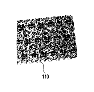
[0065] Figures 1A-1G illustrate a porous structure 110 of the present
invention. Porous
structure 110 is lightweight compared to a solid structure formed of the same
materials and
having the same dimensions. In one embodiment, porous structure 110 has a
density that is
approximately 15% to 50% that of a corresponding solid volume made from the
same
material. In one embodiment, porous structure 110 maintains a high dimensional
stability
under load. For example, the size, shape and porosity of porous structure 110
remains
substantially unchanged under heavy load and/or machining (e.g. cold working).
[0066] In a preferred embodiment, porous structure 110 of the present
invention is used
wherever a prosthesis is to have contact with bone or tissue to stabilize the
prosthesis and
induce an integrated bond between the prosthesis and the host tissue.
[0067] Porous structure 110 preferably includes a plurality of stacked bonded
sheets 200a-c
(e.g., layers, foils, plates). Each sheet 200a-c (see, e.g., Fig. 2A-2C)
preferably has at least
CA 02533534 2006-01-23
WO 2005/009729 PCT/US2004/023514
one aperture 202 that partially overlaps an aperture 202 of at least one other
sheet (e.g., of an
adjacent or non-adjacent sheet) when two or more sheets 200a-c are stacked on
one another.
In a preferred embodiment, a resulting porous structure 110 includes a sponge-
like highly
porous three-dimensional lattice having tortuous pores 210 that propagate
through structure
110. In one embodiment, at least some of apertures 202 are aligned in
substantially perfect
register to achieve a channel through at least a portion of the porous
structure 110 (e.g., as
shown in more detail below in Figs. 1D2, lE and 6B). In a preferred
embodiment, web 204
of adjoining layers are aligned to achieve a structural element through at
least a portion of
porous structure 110 (e.g., as discussed in more detail below in connection
with Fig. 6B). In
one embodiment, web 204 is a serpentine web.
[0068] MATERIALS FOR FORMING SHEETS AND STRUCTURES
[0069] In Fig. 2A-2C, there is illustrated sheet 200a, 200b, and 200c. Sheets
200a-c may be
formed from any of the materials that may be useful for constructing a porous
structure. In
one embodiment sheet 200a-c of porous structure 110 is of the same material.
In other
embodiments, two or more of sheets 200a-c of porous structure 110 are of
different materials.
In one embodiment, two or more sheets 200a-c of differing materials are bonded
together to
form porous structure 110. In some embodiments sheets 200a-c are made from non-
metals
such as ceramics, glass, polymer, paper or other manmade or natural materials.
In one
embodiment, porous structure 110 is formed by combining sheets of different
materials (e.g.,
glass, ceramic, metal, polymer, or combinations thereof) to form a hybrid
structure. In one
embodiment one or more of sheets 200a-c are textured. For example, textured
sheets are
bonded to textured or non-textured sheets. In one embodiment, at least one of
sheets 200 a-c
is a textured sheet configured to effect the surface roughness of porous
structure 110.
[0070] In one embodiment, porous structure 110 can be made in any size from
any metal or
non-metal material. In some embodiments, porous structure 110 and/or sheets
200a-c (e.g.,
11
CA 02533534 2006-01-23
WO 2005/009729 PCT/US2004/023514
as shown in FIG. 2A-D) are made from base metals such as refractory metals
(e.g., titanium,
tantalum, zirconium, hafnium, platinum, rhodium, niobium and alloys thereof)
gold, cobalt-
chrome alloys, chrome-cobalt-molybdenum alloys, aluminum, stainless steel, any
alloys
thereof or any other metal or alloy that may be chosen for its bonding
properties, chemical
inertness, bio-compatibility, mechanical strength or properties that would
render porous
structure 110 (e.g., in the form of foam or sponge) made of such material a
useful product for
a particular application.
[0071] In some embodiments, porous structure 110 and/or sheet 200a-c are made
from non-
metals such as polymers (e.g., ultra high molecular weight polyethylene
(UHMWPE),
polytetrafluoroethylene (PTFE), high density polyethylene (HDPE),
hydroxyapetite,
polyether ether ketone (PEEK), polyglycolic acid, polylactic acid,
polyoxyethylenes and
similar materials and co-polymers thereof). In one embodiment, sheets 200a
and/or structure
110 is formed from natural or synthetic, resorbable polymers preferably
biocompatible
resorbable polymers.
[0072] In one embodiment, sheet 200 and/or structure 110 is formed from woven
or non-
woven mesh.
[0073] In another embodiment, natural fibrous, protein-based or cellulosic
materials such as
papers, meshes, leathers, glass films can be made into sheets and thereafter
formed into
porous structure 110 according to the present invention. In one embodiment,
sheets 200
and/or structure 110 is made from carbonaceous materials.
[0074] In one embodiment, porous structure 110 is oxidized or otherwise
processed (e.g. as
described in U.S. Patent Publication No. 2003/0125808) to include an oxidized
coating on,
for example, the base metals. The coating preferably includes oxidized
zirconium. In one
embodiment, porous structure 110 is combined with an antifriction surface
(examples of
which are discussed herein), by for example, coating, infusing or
encapsulating.
12
CA 02533534 2006-01-23
WO 2005/009729 PCT/US2004/023514
[0075] Sheets 200a-c may also be of any width (w), length (1) or thickness
(not illustrated).
In one embodiment, the thickness of the individual sheets range from
approximately 0.001 to
approximately one (1) inch; preferably from approximately 0.001 to 0.25
inches; more
preferably from 0.005 to 0.060 inches. In one embodiment, the preferred
thickness is
determined by the type of cell or tissue growth desired. For bone ingrowth,
for example, the
preferred thickness of sheets 200a-c is between 100 to 450 microns. In one
embodiment,
sheets 200a-c have a thickness of approximately 0.012 inches and preferably
0.015 inches.
Sheets 200a-c are preferably of a substantially uniform thickness though
sheets 200a-c of
varying thickness are within the scope of this invention. In one embodiment,
the length and
width of sheets 200a-c are limited only by the size of the environment into
which it is placed
(e.g., a bonding fixture). In one embodiment sheet 200 is a two inch square
sheet of metal
(e.g., titanium) which is 0.015 inches thick.
[0076] In one embodiment, porous structure 110 is formed from polymer sheets.
In
embodiments of the present invention when sheets 200 are formed of a polymer,
aperture 202
may be directly laser machined, CNC drilled, die-cut, stamped, or injection or
compression
molded, water jet machined or otherwise formed.
[0077] In one embodiment, porous structure 110 is formed from ceramic or glass
frits. In
embodiments when sheets 200 are formed of ceramic or glass frits, aperatures
202 may be
machined by laser, abrasive jet machined, or fired as a compact or sintered
mass to the net
shape or pattern 206.
[0078] As shown in Fig. 2A, sheet 200a preferably contains at least one
aperture 202 and
more preferably a multiplicity of apertures 202. Aperture 202 is defined by
web 204. In one
embodiment, apertures 202 are 10 microns to 1000 microns wide, preferably 25
microns to
1000 microns wide and more preferably 100 microns to 450 microns wide (e.g.,
for some
13
CA 02533534 2006-01-23
WO 2005/009729 PCT/US2004/023514
bone graft applications). In a preferred embodiment, there are a multiplicity
of apertures 202
and webs 204.
100791 In one embodiment, webs 204 and apertures 202 are configured in a
predetermined
pattern 206. In one embodiment, webs 204 define pattern 206. In one embodiment
pattern
206 is a network of geometric shapes. The geometric shapes may be regular or
irregular and
may include one or more angular or curved portions. The geometric shapes may
be
pentagons, hexagons, squares, parallelograms, rectangles, circles, ovals or
any other regular
or irregular geometric shape. For example, in Fig. 2A, sheet 200a includes a
tessellation of
hexagons and pentagons assembled in a network. In one embodiment, the
selection of
pentagons and hexagons promotes a desired open pore structure such that when
sheets 200a-c
are stacked (discussed in more detail below), it is unlikely that two
apertures will precisely
align on all sides. In another embodiment, pattern 206 is random or pseudo-
random. In still
another embodiment pattern 206 is a chaotic or fractal pattern. Aperture 202
may be of any
geometric shape and may include one or more curved, straight, undercut or
beveled portions
and combinations thereof.
f00801 In one embodiment, illustrated in Fig. 2E, webs 204 define apertures
202 having a
longitudinal dimension 205a and a transverse dimension 205b. In one
embodiment,
longitudinal dimension 205a is different or equal to transverse dimension
205b. In one
embodiment, longitudinal dimension 205 a is up to 100 times or greater than
the transverse
dimension 205b. Preferably longitudinal dimension 205a is not greater than
approximately
four times the transverse dimension. In one embodiment, the transverse and
longitudinal
dimensions are between approximately 10 microns and approximately 5000
microns.
Preferably the longitudinal dimension and transverse dimension are between
approximately
100 microns and approximately 1000 microns and more preferably between
approximately
100 microns and approximately 450 microns.
14
CA 02533534 2006-01-23
WO 2005/009729 PCT/US2004/023514
100811 In one embodiment, sheets 200 are designed such that porous structure
110 is a
biomimetic structure preferably mimicking the structure of tissue (e.g.,
bone). In one
embodiment, sheet 200a-c and/or porous structure 110 is a hierarchical
structure preferably
resembling the hierarchical structures used in engineering to build rigid and
lightweight
solids. As an illustration one may consider a large complex structure that are
preferably
made of structural elements (e.g., three-dimensional pyramids or tetrahedrons)
that are
themselves made of structural elements (e.g., basic triangular structural
elements).
[0082] In one embodiment, such structures are not scale-independently self-
similar. In
another embodiment, two-dimensional scale-independently self-similar
structures (e.g.,
patterns) are stacked in a third dimension to produce a three-dimensional
structure (e.g.,
porous structure 110). The Sierpinski Fractal is an example of a scale-
independently self-
similar object, which, when repeated or stacked into a third dimension,
produces a series of
hierarchical networks or hierarchical elements.
[0083] In one embodiment, aperture 202 perforates the entire thickness of
sheet 200a. In
another embodiment, aperture 202 partially perforates (i.e., does not
penetrate through the
entire thickness) sheet 200a. In one embodiment, sheet 200a contains various
apertures 202
of a variety of penetration depths.
[0084] In one embodiment, (e.g., as illustrated in Figure 3), sheet 200 has a
first face 302 and
a second face 304. In Fig. 3A, aperture 202 passes through sheet 200 such that
passage 306
is extends from face 302 to face 304. In Fig. 3A, passage 306 include
substantially straight
walls 305a. In this embodiment, walls 305a in Fig. 3A also substantially
perpendicular to
faces 302 and 304. In one embodiment, walls 305a are at an angle that is
obtuse or acute
with respect to either face 302 or 304. Walls 305a, in one example, are a
substantially a
single surface (e.g., a single planar surface). In another embodiment, walls
305 have a
CA 02533534 2006-01-23
WO 2005/009729 PCT/US2004/023514
plurality of surfaces. For example, in one embodiment, walls 305 are of
intersecting planar
surfaces (Fig. 3A-1).
[0085] In the embodiment illustrated in Fig. 3B, passage 306 include curved
faces 305b.
Curved faces 305b may be continuous from face 302 to face 304 or the may be
discontinuous
(e.g., having a point of inflection) as illustrated in Fig. 3B. The curved
faces 305b illustrated
in Fig. 3B have undercut portion 303. In one embodiment, curved face 305b
include more
than one undercut portion (e.g., at face 302 and at face 304).
[0086] In the embodiment illustrated in Fig. 3C, aperture 202 does not extend
from face 302
to face 304. As illustrated in Fig. 3C, wall 305c may define an indentation
307 in one or both
of the faces 302 or 304. Indentation 307 may have a curvilinear cross-section,
a rectangular
cross section, an undercut cross section, a cross section that combines a
plurality of geometric
shapes (e.g., curvilinear, undercut and rectangular), a cross section that is
regular, irregular or
any other geometric cross section.
[0087] In the embodiment in Fig. 3D, there are shown a plurality of
indentations 307, some
of which are intersecting one another. Indentations 307 preferably are
oriented in varying
spatial relation to one another. In one embodiment indentations 307 create
mesas 308 at
varying distances from face 302. This effect preferably is achieved with
curved faces and/or
straight faces 305a, 305b or 305c as shown in Figs. 3A-3C. The faces can be
oriented at any
angle to the face into which indentation 307 is made.
[0088] By varying the shape of aperture 202, and by varying the face (e.g.,
302 or 304) into
which the indentation or aperture is made, one is able to specify a multitude
of combinations
of pores between and through adjacent sheets 200. Some of these combinations
are
illustrated below.
[0089] Fig. 1 G, shows one embodiment of porous structure 110 formed from
bonding two or
more sheets together and having different patterns 206a-c with apertures 202
of varying
16
CA 02533534 2006-01-23
WO 2005/009729 PCT/US2004/023514
depths. Top sheet 102a has a pattern 206a that is characterized by an X-shaped
web 204a. In
this embodiment, web 204a defines apertures 202a that perforate both sides of
top sheet 102a.
Second sheet 102b has a pattern 206b that is characterized by a web 204b that
defines a
plurality of hexagon apertures 202b. Second sheet 102b preferably is bonded to
top sheet
102a and to a third sheet 102c as described herein. Third sheet 102c has
pattern 206
including apertures 202c that perforate both sides of sheet 102c and apertures
202d that
partially perforate sheet 102c. In one embodiment, partially perforating
apertures 202d form
a meandering channel 208 in sheet 202c that intersects apertures 202c. In one
embodiment,
sheets 102a-c form a sheet set 2008. In one embodiment, a plurality of sheet
sets 2008 are
bonded together as described herein to produce porous structure 110.
[0090] PREFERRED METHODS FOR PRODUCING SHEETS 200
[0091] Fig. 6A-1 illustrates one exemplary method 6000 of producing porous
structure 110.
In step 6002, porous structure 110 is engineered at the sheet 200 level.
[0092] In one embodiment, a computer aided design file ("CAD file") is
prepared of a
candidate pattern for each sheet 200 that makes up porous structure 110. The
"CAD file"
may then be used to create pattern 206 in a predetermined configuration such
as by any of the
methods described herein. In one embodiment illustrated in Fig. 4, a model 400
of porous
structure 110 is created. Model 400 was created using SolidWorks software and
is embodied
in an assembled structure 500 Fig. 5. Model 400 preferably is previewed and if
necessary
adjustments are made so as to achieve the desired resulting network. In one
embodiment, the
artwork including, for example, details of the tortuous path of pores within
the porous
structure 110 are modeled. In one embodiment of model 400, each of the
apertures 202 and
webs 204 on each sheet 200 are modeled.
[0093] In one embodiment, design optimization is achieved, by manipulating the
order and/or
orientation of sheets 200 and/or apertures 202 and/or webs 204 in Model 400.
In one
17
CA 02533534 2006-01-23
WO 2005/009729 PCT/US2004/023514
embodiment, the size and shape of apertures 202 and/or webs 204 in sheets 200
are modeled
to achieve a desired porous structure 110. In one embodiment, the pattern 206
for each sheet
is modeled in this fashion.
[0094] In step 6004, pattern 206 is applied to sheets 200. In one embodiment,
a working
photographic master film ("photo-tool") reflecting pattern 206 is prepared
from a CAD file in
any manner known to those knowledgeable in the field of photochemcial etching.
At least
one face of sheet 200 preferably is covered with a maskant. Artwork associated
with pattern
206 is then projected onto the sheet. In one embodiment, artwork is prepared
on one or both
sides of sheet 200.
[0095] In one embodiment, the artwork on one side of a sheet varies from the
artwork on the
other side of the sheet. In another embodiment, the artwork on each side of
sheet is identical
and/or in or out of register to produce the desired results.
[0096] After artwork has been applied, sheet 200 preferably is processed in
accordance with
known mechanical, chemical and/or electrical methods (e.g., photochemical
machining) to
achieve a desired structure (e.g., open pore lattice structure). In step 6006,
apertures are
formed in sheets 200. In one embodiment, step 6006 includes removing the
maskant in
accordance with known mechanical, electrical and/or chemical methods (e.g.,
laser ablation).
Sheet 200 that conforms to pattern 206 preferably is thereby formed.
[0097] In one embodiment, aperture 202 is produced by a chemical, mechanical,
electrical or
any other process or combination of processes for creating apertures 202
(e.g., holes,
perforations, indentations, channels, or slots) in a sheet or work piece.
Apertures 202 may be
produced by direct laser machining, abrasive water jet machining, stamping
(e.g., computer
numerical controlled (CNC) stamping), drilling, punching, ion beam etching,
electrochemical
etching, photochemical etching, electrical discharge machining (EDM), other
perforation
techniques and/or combinations thereof. In one embodiment, sheet 200 is
produced by the
18
CA 02533534 2011-01-27
WO 2005/009729 PCTIUS2004/023514
methods disclosed in U.S. Patent No. 6,620,332 to Amrich.
In one embodiment, sheet 200 is produced by the methods disclosed in U.S.
Patent
No. 6,599,322 to Amrich et al. In one
embodiment combinations of methods are used to create apertures in sheet 200.
[0098] In some embodiments, the method used for perforating sheet 200 may be
specified to
enhance the performance of a finished product. For example, in applications
for which
enhanced tissue in-growth is desired, individual sheets may be partially
etched (e.g., half
etched) with a pattern on one side of the sheet to provide an additional
locking mechanism
between the in-growing tissue and the open pore structure. In another
embodiment, a
feathered edge is etched into sheet 200 providing an enhanced locking
mechanism for
ingrown tissue. For example, perforated sheets formed from the process
described in U.S.
Patent 6,599,322, may be used to produce sheets
200 with a feathered edge. In one embodiment, such a method is used to create
an effective
outer surface of a medical device (e.g., implant). One such medical device
preferably has an
increased coefficient of friction that provides improved stability and
fixation characteristics.
[0099] In one embodiment of step 6006, the forming of apertures in sheets
includes treating
sheets 200 including one or more pores, sheets 200 (e.g., of metal such as
titanium) with a
brief etch in nitric acid/hydrofluoric acid solution to remove surface
storage, debris and
handling oxidation.
[00100] In step 6008, sheets 200 with apertures 202 are stacked in a fixture.
Different
structures may be created by varying the configuration of stacked sheets 200.
In one
embodiment, sheets are stacked in sheet sets of one or more sheets each. An
aspect of pattern
206 (e.g., thickness, geometry) in sheets 200 may be varied within or among
sheet sets. In
one embodiment a plurality of sheets 200 having a substantially similar
pattern 206 may be
stacked in substantially perfect register (see e.g., Fig. 1E) to form, for
example, a first sheet
19
CA 02533534 2006-01-23
WO 2005/009729 PCT/US2004/023514
set 208 (e.g., as shown in and described with respect to FIG. 6A-2) in which
similar sheets
601a, 601b, 601c are aligned with one another. In one embodiment several sheet
sets 208,
each in substantially perfect register may be stacked to form a desired
structure. In one
embodiment one or more of the sheet sets 208 is aligned askew to one or more
larger sheet
sets. Multiple sheets sets 208 may be bonded to form porous structure 110.
[00101] In one embodiment of porous structure 110, each sheet 200 within a
particular
sheet set 208 has a substantially similar pattern of webs 204 and apertures
202. In another
embodiment of porous structure 110, each sheet set 208 has sheets 200 having a
substantially
different pattern of webs 204 and apertures 202. In one embodiment the sheet
pattern
variations differ between sheet sets 208 that are used to form porous
structure 110.
[00102] One may also achieve varying results by varying the aperture-to-web
ratio of
the individual sheets 200, for example, within sheet sets 208. The aperture-to-
web ratio is the
volumetric ratio of aperture volume to web volume for an individual sheet. In
a preferred
embodiment, aperture-to-web volume of sheets 200 ranges from 95:1 to 1:20.
Aperture-to-
web ratios may be varied, for example, by adjusting the artwork and etch
procedures to
produce sheets 200 of varying porosity, such as by creating sheets 200 with
more or fewer
complete or partial apertures 202.
[00103] One embodiment of step 6008 is illustrated in Fig. 2D. In Fig. 2D,
sheets
200a, 200b and 200c are stacked on top of one another in a desired orientation
to form a sheet
set 208. The number of individual sheets (e.g., 200a-c) in sheet set 208 may
vary from as
few as two sheets 200 to as many sheets 200 as necessary to achieve the
desired finish
product. In one embodiment, as illustrated in Fig. 2, sheets 200 preferably
are stacked in a
skewed alignment and orientation. Sheet sets 208 can include any number of
desired sheets.
Sheet sets 208 can be bonded to one another as described herein to form
repeating patters of
sheet sets.
CA 02533534 2006-01-23
WO 2005/009729 PCT/US2004/023514
[00104] Figs. 2A-C illustrates an exemplary skewed alignment wherein sheets
200a
through 200c were formed from predetermined artwork as described herein. In
one
embodiment, sheet 200b is aligned at an angle e to sheet 200a. Angle o may be
any angle
between 0 and 360 . Figs. 2A-C further illustrate an embodiment wherein each
three sheets
(e.g., sheet set 208 in FIG. 6A-2) are in skewed alignment to each other. In
one embodiment,
illustrated in Fig. 2A-2D, three substantially identical sheets are stacked
such that each sheet
is skewed at an angle to its adjacent sheet. The assembled stack then
preferably is shifted in
both axes so that its cross section is in the shape of a 10 degree lozenge.
[00105] Fig. 6A-2 illustrates a sheet set 208 that includes three sheets 601a,
601b, and
601 c with varying patterns. Sheet 601 a has a pattern of webs 604a configured
to form an
open lattice structure. Webs 604a form a crossing pattern that further defines
apertures 602a.
Sheet 601b has a pattern of webs 604b configured to form a lattice that has a
aperture-to-web
ratio that is greater than the aperture-to-web of sheet 601a. The pattern of
webs 604b on
sheet 601b aligns with the webs 604a of sheet 601a such that when the sheets
are bonded as
described herein, there will be formed a continuous structural member formed
between web
604a and web 604b. Sheet 601c has a pattern of webs 604c configured to form a
lattice that
has an aperture-to-web ratio that is greater than the aperture-to-web ratio of
sheet 601 c. The
pattern of webs 604c on sheet 601c aligns with the webs 604a and 604b such
that when
sheets 601 a, 601b and 601 c are bonded together, there is formed a porous
structural member
formed between web 604a, 604b and 604c.
[00106] In one embodiment, sheets 200 and sheet sets 208 are stacked to
achieve
structural objectives. In one embodiment, porous structure 110 is engineered
to satisfy a
particular structural or physical properties (e.g., modulus of elasticity) of
the desired finished
product. A finite element analysis is preferably performed to derive a pattern
206 (e.g., a two-
dimensional pattern) for sheets 200. Each sheet preferably reflects a
particular engineered
21
CA 02533534 2006-01-23
WO 2005/009729 PCT/US2004/023514
pattern that when assembled (e.g., bonded as described herein), will create
for porous
structure 110 a desired structural quality and/or feature(s) (e.g., a
specified modulus of
elasticity). For example, Fig. 6B illustrates porous structure 110 (both
before and after
assembly) with integral stiffening members 650. Pattern 206 is a regular
pattern of solid
regions 652 webs 653 and apertures 654. Fig. 6B illustrates and embodiment
wherein solid
regions 652 are aligned to create a desired pattern of connected stiffening
members 650. In
another embodiment, solid regions 652 may be purposefully misaligned to
achieve a different
effect. In some embodiments, solid regions 652 align to form abrupt or gradual
transition
from the foam-like structure to stiffening members 650. In one embodiment, the
resulting
stiffening members 650 form solid pillars penetrating and/or protruding
through the porous
structure 110. Integral stiffening members 650 preferably are strong enough to
withstand the
temperature and pressure of a second bonding (e.g., diffusion bonding) process
to another
material. As with entirety of porous structure 110, stiffening members 650 can
also be
machined (e.g., conventional tapping operation, cold working, machining) as
illustrated in
Fig. 1F1 and 1F2. Engineered features also include regions of interconnected
and/or non-
connected apertures 202. In one embodiment, engineered regions of unconnected
apertures
of various porosity are defined within porous structure 110. In one
embodiment, alignment
of features (e.g., stiffening members, struts, apertures, pores) from sheet to
sheet form three-
dimensional features throughout porous structure 110.
[001071 In one embodiment, sheets 200 and/or sheet sets 208 are stacked to
achieve
porosity objectives. For example, in one embodiment, it is desirable to create
porous
structure 110 with a porosity that varies throughout the three dimensional
structure. Such a
porous structure 110 is useful, for example, to facilitate both hard tissue
(e.g., bone) ingrowth
and soft tissue (ligament) ingrowth into different ends of the same structural
member.
22
CA 02533534 2006-01-23
WO 2005/009729 PCT/US2004/023514
[00108] For example, Fig. 7A illustrates examples of porous structure 110
having a
differential porosity. Fig. 7A illustrates a stepped differential porosity
wherein regions of
porous structure 700 representing different porosity are formed in the
structure. In Fig. 7A
regions of lower porosity Ll (10%) are formed on a first end 702. In one
embodiment, lower
porosity region L1 (10%) is followed by a higher porosity region L2 (20%)
which may or
may not be the same length as L1 (10%). In one embodiment, the porosity of
structure 700
increases in a stepped pattern across structure 700. In one embodiment,
regions of high
porosity are separated by regions of lower porosity. In one embodiment,
regions of lower
porosity act as barriers to certain types of material (e.g., polymer) while
allowing certain
other types of materials to pass (e.g., air). In one embodiment, regions of
differential porosity
are interconnected (e.g., interconnected apertures within one region such as
Ll and/or
interconnected pores between regions such as between L1 and L2). In another
embodiment,
regions of differential porosity are not interconnected (e.g., neither the
apertures within a
particular region such as Ll or between regions (e.g., between L1 and L2) are
interconnected). Combinations of interconnected and non-interconnected
aperture are also
within the scope of the present invention. Dimensions of apertures 202 may
vary within a
single sheet or from sheet to sheet to create porous regions across any one
sheet or region or
across more than one sheet or region.
[00109] In Fig. 7B there is illustrated a graduated porosity wherein the
porosity varies
from one end of porous structure 700 to another end of porous structure 700.
The change in
porosity however is more gradual than the change of porosity illustrated in
Fig. 7A. Porosity
of porous structure 110 may vary from sheet 200 to sheet 200, sheet set 208 to
sheet set 208
or across any one particular sheet 200 or sheet set 208.
[00110] BONDING SHEETS
23
CA 02533534 2006-01-23
WO 2005/009729 PCT/US2004/023514
[0100] In step 6010, sheets 200 and/or sheet sets 208 are bonded together. In
one
embodiment, at least a portion of web 204 of a first sheet 200 is bonded
(e.g., by the methods
disclosed herein) to at least of portion of web 204 of each adjacent sheet 200
or sheet set 208.
In a preferred embodiment, portions of adjacent webs 204 form solid bonded
intersections
between the sheets 200.
[0101] Sheets 200 and/or sheet sets 208 can be bonded by any method of
bonding, including
but not limited to vacuum diffusion bonding, chemical bonding (e.g., by
reactive species such
as epoxies, urethanes, and other appropriate adhesives), physical bonding,
explosive bonding
and mechanical bonding. In preferred embodiments, sheets 200 and/or sheet sets
208 are
laminated, vacuum-diffusion bonded and/or adhesive bonded. Other examples of
bonding
methods include hot isostatic bonding (HIP), cold isostatic bonding (CIP),
brazing, gluing,
adhesion, soldering, resistance welding, induction welding, solvent bonding,
thermal or
ultrasonic welding, mechanical interlocking, staking, swaging, riveting,
deformation, suturing
and pinning. In ceramic applications bonding preferably is accomplished by
firing a ceramic
or glass frit.
[0102] In one embodiment using vacuum diffusion bonding, sheets 200 and/or
sheet set 208
is mechanically compressed with, for example, a bonding fixture (e.g., clamp).
In one
embodiment (Fig. 7C), the bonding fixture 7000 includes two stainless steel
plates 7001 (e.g.,
3/4 inch thick type 304 stainless steel plates) with a hole 7002 near each
corner. Bolts 7005
(e.g., 5/16-18 molybdenum bolts) were then tightened sequentially from
opposite corner to
opposite corner to a sufficient torque to achieve a compression (e.g.,
compressions force of
0.002 - 0.004 inches), or a theoretical thread displacement (e.g., about
0.0138) achieved by
tightening each bolt one quarter-turn after contact. In one embodiment, the
bolts preferably
are elastically tensioned.
24
CA 02533534 2006-01-23
WO 2005/009729 PCT/US2004/023514
[01031 In one embodiment, to prevent sticking and galling, the fixture
surfaces 7010 in
contact with a sheet set 208 (e.g., comprising titanium etched foil sheets)
are coated with a
thin layer of magnesium hydroxide, boron nitride, graphite or any appropriate
high
temperature lubricant. The molybdenum bolt threads are preferably coated with
boron nitride
dispersion. In one embodiment, it has further been found that when the bonded
part is
removed, it slides easily from the fixture, because the bonding process
reduces the thickness
of sheet set 208 by approximately 0.020" per 1/2 inch thickness.
[01041 The compressed sheet set 208 may then be placed in a high temperature,
high vacuum
fixture (e.g., a programmable AVS vacuum furnace) to produce the desired
vacuum diffusion
bonding. In one embodiment vacuum pressure of approximately 10"3 atm is used
in
combination with temperatures of approximately 800 F to approximately 1250 F.
In one
embodiment, an AVS Ace 4-1280 controller and software is programmed to raise
the
temperature of the assembly to 850 C and maintain the temperature for one hour
followed by
a helium cool-down. In another embodiment, the temperature of the assembly is
raised to
900 C and maintained for four (4) hours followed by a helium cool-down.
[01051 During the heating cycle, the higher coefficient of thermal expansion
of the stainless
steel compared to the lower expansion coefficient of the molybdenum bolts
preferably adds
still more pressure loading onto the assembled stack. Thus, when the secured
sheets 200
and/or sheet sets 208 are exposed to heat, the stainless steel expands to a
greater extent that
the molybdenum bolts. As a result the pressure on the stack of sheets 200
increases and the
bond between sheets 200 can be achieved at a lower temperature. The lower
temperature is
desirable because it prevents or reduces or minimizes grain growth in the
materials used to
form porous structure 110, which reduces the strength of the metal. Also, a
more rapid
process cycle results thereby allowing more inexpensive production of the
porous structure
CA 02533534 2006-01-23
WO 2005/009729 PCT/US2004/023514
110. The close intimate contact of the metal surfaces generated by the
compression,
furthermore, allows more complete and rapid bonding.
[0106] Upon removal of the cooled assembly of sheets 200, the assembled porous
structure
110 (resembling a "foam") is completely bonded, layer-to-layer with diffusion
bonds having
a strength that preferably is substantially identical to that of the parent
metal. In destructive
bend testing performed in a press with a total pressure of 1,800 Pounds
applied to a %2 inch
diameter dowel caused a 50% "U" - shaped deformation of the part and resulted
in no bond
failures.
[0107] In another embodiment, bonding is achieved using, for example, aluminum
metal as a
brazing intermediate for certain alloys, including 6-Al 4-V Titanium alloy. In
one
embodiment, a thin sheet of aluminum foil can be laminated between each sheet
200. When
the assembly is compressed, and placed into a vacuum furnace, the aluminum
melts and
flows at a substantially lower temperature than is needed to diffusion bond
titanium and its
alloys. In regions of titanium-to-titanium contact or near contact, an
aluminum/titanium
eutectic alloy is formed. In one embodiment, some aluminum is free to diffuse
into the 6-4
titanium. Preferably, the lower temperatures needed for this process minimize
grain growth
problems frequently seen in titanium alloys when heated near its melting point
for long
periods.
[0108] Alternatively, aluminum "flake" ("Paintmakers' Powder") is dusted onto
the titanium
lattice sheets so as to minimize excess aluminum in the system. While aluminum
is
objectionable in implant applications, the use of aluminum in applications
such as aerospace
applications may be preferred.
[0109] In one embodiment, sheets 200 and/or sheet sets 208 are bonded by
explosive
bonding. Explosive bonding is considered a solid state welding process that
uses controlled
explosive energy to force two or more metals together at high pressures. The
resultant
26
CA 02533534 2006-01-23
WO 2005/009729 PCT/US2004/023514
composite system is joined with a high quality metallurgical bond. The time
duration
involved in the explosive welding event is so short, that the reaction zone
between the
constituent metals is microscopic. In one embodiment plates are accelerated
into one another
with the forces generated by an explosive detonation. In one embodiment, a
sheet of metal or
other material (e.g., a "Flyer plate") is propelled by an explosion toward a
stationary plate or
a stack of stationary plates to be joined. The Flyer plate thus yields to the
force of the
explosion as the detonation front moves across the surface of the plate.
Kinetic energy is
thereby transferred into the stationary plates as the forces at the collision
point cause the first
few molecular layers to liquefy. Plasma jets between the surfaces as the
collision point
accelerates across the plates thereby creating a full metallurgical weld.
Explosive metal
bonding is considered a cold joining process because the materials remain at
or near ambient
temperature and retain their original characteristics. Explosive bonding is
performed, for
example, by High Energy Metals, Inc. of Sequim Washington.
[0110] Explosive bonding experiments were conducted with samples of zirconium,
titanium,
and cobalt/chromium alloy sheets 200. All combinations of these materials were
successfully
bonded using explosive bonding. In a first series of tests, a niobium
interlayer was placed
between the two metals to be bonded. A niobium layers is used, in one
embodiment, when
metals are to be heated at a later stage. The niobium interlayer can prevent
eutectic formation
between the principle metals to be bonded. Metals were also successfully
explosion bonded
without a niobium interlayer.
[0111] In one embodiment, adjoining sheets 200 and/or sheet sets 208 are
bonded with
interlocking tongue and groove joints. In one embodiment, adjoining sheets 200
and/or sheet
sets 208 are bonded together with a combination of two or more bonding
techniques. In one
embodiment, for example, the interlocking tongue and groove joints are
combined with
another bonding technique (e.g., diffusion bonding, explosion bonding)
described herein. In
27
CA 02533534 2006-01-23
WO 2005/009729 PCT/US2004/023514
one embodiment, layers of different materials are bonded together by combining
two or more
bonding techniques such that the strength of the bond formed is determined by
a combination
of two or more of the bonding techniques.
[01121 The bonding process described herein is not intended to limit the
geometry of porous
structure 110. Sheets 200 having any geometry or three dimensional profile
(e.g., curved,
flat, serpentine, wave-like) are bonded together. In one embodiment, sheets
are preformed in
a shape configured to connect to a solid material (e.g., the a solid medical
implant or
component of a medical implant) and are bonded together in that configuration.
In one
embodiment, illustrated in Fig. 7D, porous structure 110 may be formed in a
cylindrical
geometry. In one embodiment, there is fixture 770 having a an expandable
mandrel 755 and
a cylinder 762. In one embodiment, fixture 770 is a mold within which
assembled sheets are
stacked for bonding. Porous structure 110, in one embodiment, is assembled by
rolling
perforated sheets 752 onto mandrel 755. Preferably sheets 752 are tightly
rolled onto
mandrel 755 to form rolled assembly 760. In one embodiment, rolled assembly
760 is
pressed into cylinder 762 which preferably has outer sleeve 763. In one
embodiment,
mandrel 755 and cylinder 762 are of materials with differing coefficients of
thermal
expansion such that when the fixture is heated, mandrel 755 expands to a
greater degree than
cylinder 762 and outer sleeve 763 thus creating the pressure necessary to bond
together
perforated sheets 752. In one embodiment, mandrel 755 preferably is stainless
steel while
cylinder 762 and outer sleeve 763 are molybdenum. In one embodiment, mandrel
755 has
cladding 765. Cladding 765 may be any material that is selected to prevent a
bonding
formation (e.g., the formation of a eutectic) between the between mandrel 755
and rolled
sheets 752. Cladding 765 may be any material that prevent mandrel 755 from
sticking to
rolled sheets 752. Thus, for example, cladding 765 may be tantalum, niobium or
molybdenum. Preferably, cladding 765 is graphic or boron nitride. In one
embodiment, the
28
CA 02533534 2006-01-23
WO 2005/009729 PCT/US2004/023514
material for cladding 765 is selected to prevent eutectic formation and/or
dissolution with
titanium sheets 752. In one embodiment, either or both of mandrel 755 and
cylinder 762 are
constructed of porous material (e.g., porous material 110)
[0113] In one embodiment, after the bonding cycle is complete, mandrel 755 is
pressed or
machined out. In one embodiment, cylinder 762 is parted longitudinally to
removed bonded
porous structure 110.
[0114] POST PROCESSING
[0115] In step 6012 porous structure 110 is post-processed. In one embodiment,
porous
structure 110 may be post processed by any chemical, mechanical or electrical
process after
porous structure 110 is formed (e.g., bonded). In one embodiment, an etching
step may be
performed on the bonded stack of lattice sheets 200 forming porous structure
110. In one
embodiment, this etching step increases the pore volume of the structure 110.
[0116] In one embodiment it is desirable to remove stepping artifacts (e.g.,
resulting from an
etching process) from the joints of individual layers (e.g., sheets 200) in a
sheet stack 208.
Stepping artifacts may be removed by, for example, a post-processing machining
method.
Figure 1A shows porous structure 110 prior to post-processing. In one
embodiment, bonding
of sheets 200 produces inside corners that are not razor sharp but show
evidence of material
flow. These small meniscuses preferably are removed by post-processing (e.g.,
a post-
etching step). In one embodiment, the post-processing produces smooth surfaces
within the
structure. In one embodiment, the post-processing results in an adjustment of
the pore-to-
web ratio. Post processing may preferably also include mechanical working such
as shot
peening, and machining.
[0117] In one embodiment, post-processing of porous structure 110 includes
oxidation of
porous structure 110. In one embodiment, porous structure 110 is constructed
at least in part
from zirconium or zirconium alloy sheets 200. After post processing, porous
structure 110
29
CA 02533534 2011-01-27
WO 2005/009729 PCTIUS2004/023514
preferably already includes or is further processed to include an oxidized
zirconium surface.
The oxidation step may be performed as described in U.S. Patent No. 6,652,586
or U.S.
Patent Publication No. 2003/0125808.
[0118] In another embodiment, one or more polymers are infused or otherwise
caused to
migrate throughout at least a portion of the open pore structure of porous
structure 110
according to the present invention. Polymers such as ultra high molecular
weight
polyethylene (UHMWPE), polytetrafluoroethylene (PTFE), high density
polyethylene and
hydroxyapetite are among those polymers that will find utility in the present
invention. Other
useful polymers include polyether ether ketone (PEEK), polyglycolic acid,
polylactic acid,
polyoxyethylenes and similar materials. Preferred polymers include nylons,
urethanes,
silicone elastomers, some epoxies (e.g., sufficiently hydrolytically stable
polymers such as
those used in pacemaker domes), PEEK polyacetals, polyesters and other such
recognized
polymers. In one embodiment, the polymer is selected for characteristics such
as wear-
resistance, coefficient of friction and chemical inertness and combinations
thereof. One
method of infusing polymer through porous structure 110 is by compression
molding. By
infusing polymer into porous structure 110, the complexity of the structure
enhances the bond
between the polymer and the structure. In one embodiment, porous structure 110
is
substituted for the open-celled lattice described in U.S. Patent No. 6,087,553
which is hereby
incorporated by reference.
10119] Fig 13A illustrates a porous structure 1300 with infused polymer 1310,
and Fig. 13B
illustrates a cross section of porous structure 1300 infused with polymer
1310.As illustrated
in Fig. 13B, porous structure 1300 includes sheets 1352 with pores 1353 that
have been filled
with polymer 1351. Pores 1353 can have any shape defined by the features of
sheets 1352 or
by a combination of sheets 1352. In one embodiment, the features of sheets
1352 includes
CA 02533534 2011-01-27
WO 2005/009729 PCTIUS2004/023514
feathered edges 1354, round edges 1355, hexagonal pores 1351 and a multitude
of other
irregular and regular shapes. Sheets 1352 preferably are titanium sheets. In
one
embodiment, RTV silicone rubber is used as polymer 1310 infused as a filler.
In another
embodiment, epoxy resin is the polymer and the composite porous structure 110
is hybrid
conductive/dielectric structure, or an air-tight composite of a high stiffness-
to-weight ratio.
[0120] Other methods of post processing include application of a porous
coating and/or
application of a polymer coating or other coating such as an osteotropic,
osteocompatible or
precursor material such as a hydroxyapetite or any cell or tissue growth
enhancing or
accelerating factor including human growth hormone, epidermal growth factor,
and/or bone
growth factors. Other embodiments may include the application of anti-
infection, anti-
rejection or therapeutic type drugs either on the surface of or within porous
structure 110. In
one embodiment, anti-infection, anti-rejection or therapeutic type drugs are
incorporated into
a polymer which is applied to the surface of porous structure 110 or infused
into porous
structure 110. In one embodiment, at least one of sheets 200 includes a
polymer that includes
an active ingredient such as a drug or a functional material such as a
coating.
[0121] In one embodiment, porous structure 110 may be plasma sprayed with a
bonding
agent which is in turn covered with a porous ceramic coating which would allow
the in-
growth of bone spicules into the pores, for example, as that process is
described in U.S.
Patent No. 4,145,764 .
[0122] APPLICATIONS
[0123] In one embodiment illustrated in Fig. 8A-C, a plurality of the sheets
form a bonded
sheet set 208 containing porous regions 810, blank regions 820 and web 830. By
aligning
porous regions 810, blank regions 820 and/or webs 830 in a predetermined
configuration,
design affects can be achieved which are engineered to solve the need of a
particular
application. Because each layer may be different, complex structures of open
pores with
31
CA 02533534 2006-01-23
WO 2005/009729 PCT/US2004/023514
integral solid support or attachment regions may readily be prepared. Solid
regions of porous
structure 110 preferably provide additional stiffness to porous structure 110,
and/or form
mounting flanges, bosses, or attachment points.
[0124] In another embodiment a variety of three-dimensional structures may be
formed from
porous structure according to the present invention. Figs. 8A-C illustrates a
variety of shapes
that may be formed as described above. Additional geometric forms can be
achieved by, for
example, forming blocks of open pore structures and machining (e.g., by EDM)
the block to a
desired geometry such as cylinders, spheres, cones, and cubes. Among the
benefits of the
porous structure of the present invention is the ability to cold or hot work
the porous structure
without a significant loss in porosity.
[0125] In one embodiment, illustrated in Fig. 9, open pore reticulated
structure 900 is
bisected by boundary 910. Boundary 910 is unperforated or partially
perforated. In one
embodiment, Boundary 910 is created from sheet 200 having partial aperture 307
as shown in
Figs. 3C-3D. In one embodiment, one or more sheets 200 are included in
boundary 910.
[0126] In one embodiment, open pore region 920 on one side of boundary 910,
has the same
or different porosity characteristics as open pore region 930 on the other
side of boundary
910. Thus, for example, an open pore reticulated structure of the present
invention may have
one or both sides of a partition are sufficient or optimized for bone
ingrowth, or one side for
bone or tissue ingrowth and one side is sufficient or optimized, for example,
for a natural or
synthetic polymer, bone or tissue attachment. Such embodiments are suitable
for producing
medical implants such as, for example, the implants described in FIGS. 10, 1
1A, 11B, and
12A.
[0127] Any of the embodiments of the present invention may be treated with any
coating,
including but not limited to an active ingredient, pharmaceutical or a natural
or synthetic
tissue or combinations thereof. In one embodiment, for example, open pore
region 920 on
32
CA 02533534 2006-01-23
WO 2005/009729 PCT/US2004/023514
one side of boundary 910 may be treated with a composition containing a
particular active
ingredient, pharmaceutical, functional material or tissue, and open pore
region 930 on the
other side may be treated with a composition containing the same or a
different active
ingredient, pharmaceutical, functional material or tissue (e.g., human growth
hormone,
fibroblasts, stem cells, or any material or compound that may facilitate
treatment, tissue
growth, anti-infection, anti-rejection and/or therapeutic type drugs or
compounds).
[0128] In another embodiment, fluid being carried in the open pore structure
920 on one side
of solid boundary 910 may be separated from fluid carried in the open pore
structure 930 on
the other side of boundary 910. Boundary 910 may be solid, semi-solid,
textured or of a finer
porosity that prevents the passage of fluids, fibers, drugs or other
compounds.
[0129] Another example of such a configuration may be a heat exchanger such as
where, for
example, transmission fluid is being carried on one side and antifreeze on the
other.
[0130] OTHER USES OF POROUS STRUCTURE
[0131] In one embodiment, porous structure 110 is connected (e.g., bonded) to
a medical
implant. Among the categories of medical implants that will be improved by
porous structure
110 are orthopedic devices and implants (e.g., spinal implants, digital
implants), dental
devices and implants, augmentation devices and implants (e.g., augmentation
plates,
augmentation blocks, augmentation discs and preformed acetabular cups) and
articulating
devices and implants (e.g., spinal pieces).
[0132] ORTHOPEDIC APPLICATIONS
[0133] It will be appreciated by those of skill in the art that the specific
embodiments
disclosed herein are exemplary and that porous structure 110 including hybrid
composites
that include a polymer, and the various configurations described can be
utilized in any
orthopedic design to achieve the objectives and benefits described herein.
33
CA 02533534 2006-01-23
WO 2005/009729 PCT/US2004/023514
[0134] Porous structure 110 with infused polymer or coupled to a polymer
(e.g., UHMWPE)
has especially significant applicability to vertebral prosthetics such as
orthopedic implants
(e.g., "spinal cage" implants) and other orthopedic implants such as
acetabular cups, because
of the shock-absorbing and/or physiological and/or chemical properties of some
polymers in
combination with the strength of the lightweight porous structure 110.
[0135] In one embodiment, illustrated in Fig. 10 a selected polymer (e.g.,
UHM)APE) or
other material is infused to a predetermined depth of defined region 1010 of
an open pore
reticulated structure 1020. In a preferred embodiment, the pore volume in
defined region
1010 is not greater than 45%. In one embodiment, the bond depth preferably is
not less than
mm. In one embodiment, polymer 1030 is pressure injected into defined region
1010.
Polymer 1030 may also be infused into defined region 1010 by compression
molding or any
other suitable process. In one embodiment, region 1010 is defined by a
boundary 910 (as
shown in Fig. 9) within porous structure 110. In one embodiment, boundary 910
is textured
or has a fine porosity. In one embodiment, during compression molding, polymer
is
substantially blocked from passing through boundary 910 (e.g., into the tissue
growth portion
of porous structure 110) but, air passes through boundary 910. In one
embodiment, polymer
infusion preferably is controlled by controlling temperature and pressure
conditions during
polymer infusion or compression molding. By controlling temperature and
pressure, a skilled
operator will be able to control the depth of polymer 1030 in defined region
1010.
[0136] Device 1000 includes a resilient polymer section 1030. Polymer 1030 may
be an
elastomer (e.g., resilient 40 Durometer urethane) or any other type of polymer
depending on
the desired application. Polymer 1030 is securely molded between two porous
structures
110. In one embodiment, shock loads are applied to device 1000 and polymer
1030 dampens
or absorbs at least a portion of the shock. One application may be for use in
spinal implants.
34
CA 02533534 2011-01-27
WO 2005/009729 PCT/US2004/023514
[0137] Fig. I IA and 1 IB illustrate an embodiment of a spinal implant 1100 of
the present
invention. Spinal implant 1100 includes porous structures 1110a and 1110b and
polymer
1120. Polymer 1120 has been infused into a portion of porous structure 1110a
and into a
portion of porous structure 1110b creating an implant for use in replacing a
spinal *disc for
portions of vertebra 111 la and 111 lb. Polymer 1120 is any bioconpatible
polymer that a
person skilled in the art will select for this application. Preferred polymers
include nylons,
urethanes, silicone elastomers, some epoxies (e.g., sufficiently
hydrolytically stable polymers
such as those used in pacemaker domes), PEEK polyacetals, polyesters and other
such
recognized polymers. As illustrated in Figs. 11A and 11B, bone tissue I110d is
encouraged
to migrate into porous structure 1110 thereby creating a strong bond between
implant 1100
and vertebra 1111. In one embodiment, bone migration is encouraged by methods
described
in U.S. Patent No. 6,599,322 or U.S. Patent No. 7,018,418. In one
embodiment, porous structure 1110 has surface features that produce surfaces
that are self-
grafting and which, for example, shear the surface of bone or other tissue
upon implantation
and pack the bone or tissue material into the implant to promote bone or
tissue in-growth or
on-growth.
[0138] In one application, porous structure 1110 is constructed from a
biocompatible
resorbable polymer sheets 200. Over time, as the resorbable polymer is
consumed by the
body, the bone tissue that migrates through the porous structure 1110 will
bond to the
polymer 1120 for a disctvertebra bond that very nearly approximates the
natural connection
between disc and vertebra.
[0139] SPINAL SPACERS
[0140] U.S. Patent Nos. 6,673,075 and 5,961,554
describe porous intervertebral spacers. In one embodiment, porous structure
110 is
CA 02533534 2006-01-23
WO 2005/009729 PCT/US2004/023514
used to form porous intervertebral spacer 1130 (Figs. 11C -11E). In one
embodiment,
porous intervertebral spacers 1130 are inserted between adjacent vertebrae
1136, 1138, for
example, by replacing a portion of intervertebral disc 1137 and engaging
portions of the
adjacent vertebral bodies 1136, 1138, and 1140. In one embodiment,
intervertebral spacers
1130 are surgically inserted between vertebrae 1138 and sacrum 1140. In one
embodiment, a
plurality of spacers 1130 are used. In one embodiment, the plurality of
spacers are inserted
adjacent to one another. The number of intervertebral spacers 1130 and the
location in which
those spacers are placed are selected based upon factors well known in the
art. In one
embodiment, three intervertebral spacers 1130 having a rectangular
configuration are
implanted (Figs. 11D and 11F).
[0141] Porous intervertebral spacers 1130 of any size or shape can be
manufactured using the
methods described herein. Porous intervertebral spacers 1130 are of any
geometrical
configuration and are preferably rectangular, cubic, cylindrical, octahedron,
spherical or any
other Euclidean solid (e.g., Fig. 11E, 11F). Porous intervertebral spacers
1130 may be of any
desired symmetry.
[0142] In one embodiment for manufacturing porous intervertebral spacers 1130,
the desired
shape is computer designed with the desired perforated patterns in individual
sheets (e.g.,
sheets 200). The dimensions of the individual sheets are determined based upon
the desired
dimensions of the finished porous intervertebral spacer 1130. For example, in
one
embodiment, a cube is made by a stack of four-sided square sheets 200 wherein
the final
bonded height equals the dimensions of the sides of the square sheets.
[0143] In another embodiment, illustrated in Figs. 11H and 11 G a spherical or
substantially
spherical porous structure (e.g., 1130) is made of round perforated sheets 200
with varying
individual diameters that correspond to the sheet's position along an axis of
the sphere. Thus
for example, in one embodiment, each sheet 200 represents a "slice" through a
sphere,
36
CA 02533534 2006-01-23
WO 2005/009729 PCT/US2004/023514
wherein the thickness of the slice is the thickness of the individual sheet
200 (Fig. 11 G). In
one embodiment, a stack of sheets 208 to be bonded would consist of a set of
circles having a
very small circle at one end (e.g., a pole of the sphere) with a slightly
larger circles stacked
above the smaller circle until, at the assembly of half the sheets, one would
reach the
equatorial dimension of the intended sphere. The remaining sheets, in one
embodiment,
would then be sequentially smaller (e.g., culminating in the opposing pole of
the sphere; Fig.
11 G).
[0144] In one embodiment, intervertebral spacers are symmetrical about at
least three
perpendicular axes. In one embodiment, the spacers are suitable to being
installed
laparoscopically at least in part due to the uniformity of their orientation
along numerous axes
(e.g., being orientation independent)
[0145] ACETABULAR CUP
[0146] Fig. 12A illustrates one configuration of the present invention for use
in applications
requiring high porosity and low friction characteristics such as device 1200
(e.g., a hip
prosthesis). Porous structure 1210 has been partially infused with polymer
1220 such as by
any other methods described herein. Thus there is a portion of porous
structure 1210 that has
no polymer infusion and a portion of porous structure 1210 that has been
polymer infused
(e.g., the polymer is interdigitated within porous structure 1210). In one
embodiment,
polymer 1220 is a UHMWPE, cross-linked polyethylene (XLPE) or any other
biocompatible
polymer or polymer based composite that are known to those skilled in the art
(e.g., nylons,
urethanes, silicone elastomers, some epoxies, PEEK polyacetals, polyesters and
other such
recognized polymers). In Fig. 12A, polymer 1220 has been formed as a first
bearing surface
1230. First bearing surface 1230 can be formed by molding or by machining by
methods
well known in the art.
37
CA 02533534 2011-01-27
WO 2005/009729 PCTIUS2004/023514
[0147] In one embodiment, porous structure 1210 can be machined (e.g., cold
worked) to
form the concave face of an acetabular cup (e.g., bearing surface 1230).
Porous structure
1210 may then be treated (e.g., oxidized, or infused with polymer) to achieve
any of the
desirable qualities of bearing surface 1230 which are known to those of skill
in the art (e.g.,
low friction, inert, therapeutic). In one embodiment, a polymer lining is
infused within an
acetabular cup formed by machining to form first bearing surface 1230. In one
embodiment,
because it is only partially infused with polymer 1220, porous structure 1210
remains
available for migration of bone tissue (e.g., from an adjoining shoulder, arm,
leg or pelvic
bone) which will form a strong bond between, for example, the implant and the
tissue.
[0148] There is also shown in Fig. 12A a second bearing surface 1250. Second
bearing
surface 1250 is configured to articulate about first bearing surface 1230. In
one embodiment
second bearing surface 1250 is a femoral head first bearing surface 1230 is a
lining for an
acetabular cup. Second bearing surface may also be a humerus head or any other
similar ball
device useful in a ball and socket application.
[0149] Porous structure 1240 and second bearing surface 1250 can be of the
same or different
materials including any of the refractory materials and polymers described
herein. Porous
structure 1240 and second bearing surface 1250 are bonding by any of the
methods described
herein more preferably by diffusion bonding. In preferred embodiments head
second bearing
surface 1250 has an oxidized zirconium surface as described in U.S. Patent No.
6,652,586.
Second bearing surface 1250 may also be
zirconium or zirconium containing metal alloy coated via in-situ oxidation
with a surface of
blue-black or black oxidized zirconium as described in U.S. Patent No.
5,037,438.
Second bearing surface 1250 may also include a carbide
coating as described in U.S. Patent No. 3,677,795.
Second bearing surface 1250 may be white or beige oxidized zirconium. Second
bearing
38
CA 02533534 2006-01-23
WO 2005/009729 PCT/US2004/023514
surface 1250 may be of any other biocompatible material. In one embodiment,
one of second
bearing surface 1250 or porous structure 1240 are made of polymer (e.g., any
of those
disclosed herein) and the other of second bearing surface 1250 or porous
structure 1240 are
made of a metal (e.g., any of those disclosed herein). In one embodiment, one
of second
bearing surface 1250 or porous structure 1240 are made of titanium and the
other of second
bearing surface 1250 or porous structure 1240 are made of zirconium.
[0150] Porous structure 1240 and second bearing surface 1250 can be formed
separately and
bonded by any method known to those skilled in the art including but not
limited to those
methods described herein for bonding sheets 200 to one another. Preferably,
porous structure
1240 and second bearing surface 1250 are bonded together by diffusion bonding.
In a
preferred embodiment, porous structure 1240 is configured to approximate any
portion of the
neck (e.g., femoral or humerus neck). Porous structure 1240 can also be
incorporated into
any portion of the prosthetics identified in U.S. Patent No. 6,652,586 that
illustrate a textured
regular or irregular surface. Applying porous structure 1240 as a textured
regular or irregular
structure as described herein preferably will encourage tissue to migrated
throughout porous
structure 1240 to form a secure bond between prosthesis 1200 and the adjacent
tissue (e.g.,
femur or humerus tissue).
[0151] Porous structure 1210 may be incorporated into any portion of a
prosthetic device
including those prosthetic devices with a ball and socket joint (e.g., hip,
shoulder). In Fig.
12B, illustrating one embodiment of a prosthetic hip, porous structure 110 may
be
incorporated into the acetabular cup, 1261, lining 1265, femoral head 1266,
and hip joint
stem 1262. Porous structure 110 may also be used as a substitute for any
textured prosthetic
surface such as textured surface 1260 on hip joint stem 1262.
[0152] In one embodiment, porous structure 110 is used as a liner 1265 for an
acetabular cup
(e.g., that has been damaged by a failed implant that had to be removed). In
one
39
CA 02533534 2006-01-23
WO 2005/009729 PCT/US2004/023514
embodiment, the liner is a hemispherical liner. In one embodiment, an
acetabulum is
enlarged (e.g., by the prior surgery and by the implant failure) and bone loss
has occurred to
the extent that a hemispherical liner needs to be installed. Preferably, the
hemispherical liner
has a cup-like shape with perforations for attachment of hardware. The method
of attaching
hardware to the perforations may be any method known to those of skill in the
art including
the use of adhesives such as cement.
[0153] As show in Fig. 12D, acetabular cup 1261 may be prepared by forming
sheets 200
into a series of annular rings 1263 that are slices of a partial or full
sphere, with an outer
region having a desired open porous pattern, and a smooth inner layer or a
porous inner layer.
In one embodiment, the desired shape is formed during the diffusion bonding
process. In one
embodiment, porous structure 110 is machined or forged into a desired shape
after the
diffusion bonding process. In one embodiment, after diffusion bonding, finish
machining,
forming and/or forging the annular rings, the resulting acetabular cup 1261 is
a hemisphere
having an outer region 1269 that is an assembled porous structure 110
optimized for (e.g., to
accept) bone ingrowth, and having an integrally formed inner spherical region
1268 that is
smooth or porous, uninterrupted metal or polymer. In one embodiment, one or
more of the
regions are separated by a barrier layer (e.g., 910 in Fig. 9) that is solid,
semi-solid, textured
and/or of a finer porosity than the adjacent regions. In one embodiment, inner
surface 1268 is
made of an open pore structure region according to the present invention
having a porosity
and internal geometry that are optimized for an attachment of a metal (e.g.,
zirconium) or a
polymer (e.g., compression-molded UHMWPE).
[0154] As shown in Fig. 12E, any ball and socket joint 1290 can be prepared by
combining
(e.g., as described herein) porous structure 1291 according to the present
invention, and
lubricious structure 1292 (e.g., zirconium or polymer). In one embodiment, a
medical
implant according to the present invention includes an intermediate layer 1293
of any
CA 02533534 2011-01-27
WO 2005/009729 PCTIUS2004/023514
material described herein, including but not limited to titanium, between
porous structure
1291 and lubricious structure 1292.
[0155] KNEE
[0156] The present invention is useful for any prosthetic knee design
including multi-piece,
uni-piece and partial knee replacement systems. U.S. Patent Nos. 6,652,586 and
6,494,914
disclose a knee prosthesis as illustrated in Fig. 12C. Knee
prosthesis 1250, illustrated in Fig. 12C, includes a femoral component 1270
and a tibial
component 1280. Femoral component 1270 includes condyls 1272 and pegs 1271.
Tibial
component 1280 includes a tibial base 1282 and one or more pegs 1283. Condyls
1272 in the
present invention may have a solid bottom surface 1273 (e.g., coated with an
oxidized
zirconium surface) and an upper surface 1274 (e.g., including a porous
structure 110 as
described herein. Porous structure 110 can be used to form all or part of any
component of
knee prosthesis 1250 including femoral component 1270, tibial component 1280,
tibial base
1282 condyles 1272, pegs 1271 and 1281, and grooves 1283.
[0157] In one embodiment, upper surface 1274 and lower surface 1273 are formed
together
by the stack bonding process described herein and then shaped (e.g., by cold
working the
bonded piece). In one embodiment, the bonded piece is hot formed or forged to
the desired
shape. In one embodiment, condyls 1272 are formed by bonding (e.g., as
described herein
such as by diffusion bonding) a plurality of pieces. For example, in one
embodiment,
separate pieces that include upper surface 1279a and lower surface 1279b
respectively are
bonded together to form condyl 1272. In one embodiment, peg 1271 is at least
partially a
porous structure and is bonded to upper surface 1274 (by e.g., diffusion
bonding).
10158] In one embodiment, tibial base 1282 has an upper surface 1283 and lower
surface
1284. In one embodiment upper surface 1283 is non-porous surface coated with
oxidized
zirconium, and a lower surface 1284 that is formed from a porous structure 110
of the present
41
CA 02533534 2006-01-23
WO 2005/009729 PCT/US2004/023514
invention. Upper surface 1283 and lower surface 1284 may be formed together or
formed
separately and bonded together as described herein. In one embodiment, peg
1281 includes a
porous structure 110 of the present invention. In one embodiment, peg 1281 is
integral to
lower surface 1284. In another embodiment, lower surface 1284 and peg 1281 are
formed
separately and bonded together as described herein. Upper surface 1283, in one
embodiment,
is a polymer (e.g., compression molded UHMWPE) that is compression molded into
lower
surface 1284.
[0159] In one embodiment, Illustrated in Fig. 12F, a dome shaped bearing
surface 12410
(e.g., such as that preferred in patella implants and tibial trays) is affixed
to a base 12420
having disk 12425 and stem 12430. In one embodiment, bearing surface 12410 is
an
antifriction surface. Any antifriction material may be used to form bearing
surface 12410. In
one embodiment, bearing surface 12410 includes or is treated with an
antifriction surface. In
one embodiment, the antifriction surface includes zirconium oxide. In another
embodiment,
the antifriction surface includes titanium nitride. In one embodiment, bearing
surface 12410
is titanium that is coated with zirconium oxide. In one embodiment,
antifriction surface
treatments can also include the bonding of a suitable polymer (e.g., PEEK,
UHM)APE). In
one embodiment, the surface treatment includes molding the suitable polymer
into and/or
onto a surface (e.g., as illustrated in Figs. 10, 12A).
[0160] Base 12420 preferably is at least partially formed of porous structure
110. Bearing
surface 12410 can be fixed to base 12420 by any method known to those of skill
in art. In
one embodiment, bearing surface 12410 is affixed to base 12420 by compression
molding. In
one embodiment bearing surface 12410 and base 12420 are formed of a single
contiguous
material. Base 12420 may be of a single contiguous piece or it may be formed
from a
plurality of components. In one embodiment, base 12420 is formed in separate
sections and
bonded together. Stem 12430 may provide lateral fixation in various
applications and may be
42
CA 02533534 2011-01-27
WO 2005/009729 PCTIUS2004/023514
formed of solid metal or porous structure 110 having the same or different
porosity than base
12420. At least a portion of base 12420 (e.g., stem 12430), in one embodiment,
is a solid
body having a textured outer surface as disclosed in U.S. Patent No.
7,018,418.
101611 In an embodiment illustrated in Fig. 12G, a bearing surface 12310 is
bonded to or
integral with anchor 12320. Anchor 12320, in one embodiment, is an adherent
implantable
porous structure 110 used to anchor the structure. In one embodiment, bearing
surface 12310
and/or anchor 12320 allow over-growth of tissue (e.g., cartilage). In one
embodiment,
improved tissue adhesion is achieved by providing oxidized zirconium that will
self-burnish
adjacent tissue (e.g., bone surfaces adjacent cartilage), while allowing
certain tissue (e.g.,
cartilage) in-growth to occur. In one embodiment, there is less risk of
scraping bone during
cartilage in-growth and overgrowth. In one embodiment, a smooth outer surface
coated with
an antifriction coating (e.g., as described herein) may serve as a temporary
joint to prevent
excessive abrasion or wear of tissue (e.g., bone) which may contact the
implant immediately
after implantation. In one embodiment, the smooth, antifriction outer surface
can protect
contacting tissue (e.g., bone) from abrasion until other tissue (e.g.,
cartilage) can grow to
interpenetrate the interfacial region.
[0162] U.S. Patent No. 5, 024,670 describes
a patella implant. In one embodiment, illustrated in Figs. 12H and 121 is
patella button
prosthesis 12201 of the present invention. Porous structure 110 may be
incorporated into any
or all of the components of patella implant 12201 including outer bearing
surface 12202,
backing component 12203 and dome 12204. Outer bearing surface 12202 may have
any
geometrical configuration including symmetrical and asymmetrical in relation
to the center of
backing component 12203. Outer bearing surface may be porous structure 110
that is bonded
to achieve its geometrical configuration or it may be porous structure 110
that is machined to
43
CA 02533534 2006-01-23
WO 2005/009729 PCT/US2004/023514
achieve its geometrical configuration. Outer bearing surface 12202 may be of
any material
preferably selected for its biocompatibility, wear properties and articulation
properties
including those materials described herein that are useful to form porous
structure 110. In
one embodiment, outer bearing surface 12202 is any antifriction material. In
one
embodiment, outer bearing surface 12202 is compression-moldable polymer. In
one
embodiment, outer bearing surface 12202 is UHMWPE, PEEK, ceramic or an
appropriate
metal (e.g., one that may be treated with an antifriction surface as described
above such as
zirconium or titanium). Antifriction surface treatments include, e.g., bonding
of a suitable
polymer, such as PEEK or UHMWPE as antifriction surfaces (e.g., Fig. 12A) and
those
described herein.
[0163] Backing component 12203 may be any material and preferably is
constructed from
the porous structure material 110 described herein. Outer bearing surface
12202 is preferably
removably or nonremovably fixed to a backing component 12203. Preferably,
outer bearing
surface 12202 is compression molded onto a porous structure 110 (e.g., onto
backing
component 12203).
[0164] In one embodiment, backing component 12203 can be of any shape. In one
embodiment, backing component 12203 has a dome 12204. Dome 12204 preferably is
fixed
to outer bearing surface 12202 which takes on the domed shape of backing
component
12203. In another embodiment, backing component 12203 and outer bearing
surface 12202
have different shapes (e.g., outer bearing surface 12202 having a rounded
surface and
backing component 12203 having a substantially flat surface).
[0165] HYBRID COMPOSITES
[0166] Fig 13A and 13B illustrates structural components 1300 that were
constructed using
the methods described herein. Porous structure 1310 was formed as described
above and
then altered using convention machining techniques (e.g., CNC machining, EDM).
In one
44
CA 02533534 2011-01-27
WO 20051009729 PCT/US2004/023514
embod ment, porous structure 1310 is configured as a polymer engaging
structure. In one
embodiment, polymer is preferably infused into porous structure 1310 to take
up substantially
all of the pore space within structure 1310. The result is a solid,
lightweight structural
composite that is available for any purpose to which one of skill in the art
can apply. Other
hybrid composites can be prepared by infusing, for example, metal porous
structure 110 with
reactive resin materials such as epoxies, silicones, polyester resins,
acrylics, etc. The result is
preferably a solid material of great strength which possessing other
beneficial properties of
the infused materials. (e.g., acoustic damping, energy absorption, etc.). In
one embodiment,
radio opaque polymers (e.g., barium filled polymers) are infused within porous
structure 110.
101671 Fig. 13C illustrates an exemplary hybrid structure 1370 containing
porous structures
having different degrees of porosity. In one embodiment, hybrid structure 1370
include
surface feature 1376 formed from textured solid surfaces. In one embodiment,
hybrid
structure 1370 has porous regions 1372 and semi-solid 1374 or solid regions
1375. In one
embodiment shown in Fig. 13D, when hybrid structure 1370 is formed it contains
porous
structure regions 1377 and solid regions 1375. In one embodiment, porous
structure 1377
and solid region 1375 are formed separately and bonded together to form a
composite. Solid
regions 1375 may be formed in any geometric shape. Solid regions 1375 are
preferably
.formed at any location in hybrid structure 1370. For example, as discussed
herein, solid
region 1375 may be a solid core in hybrid structure 1370 (e.g., core 1407 as
shown in Fig.
14D). In one embodiment, solid region 1375 is formed at the physical boundary
of hybrid
structure 1370 (e.g., at the corners 1378 as shown in Fig. 13D). After hybrid
structure 1370
is formed, solid regions 1375 and porous structure regions 1377 my be post-
processed as
described herein. In one embodiment, post-processing may include forming a
texture on
solid region 1375 such as those textures described in U.S. Patent No.
6,599,322 and U.S.
Patent No. 7,018,418. Porous
CA 02533534 2011-01-27
WO 2005/009729 PCTIUS2004/023514
region 1372 and solid region 1375 (or semi solid regions 1374) may be of
substantially
similar or substantially dissimilar materials.
[01681 As shown in Fig. 13E, in one embodiment, hybrid structure 1370 is
formed by
assembling sheets 1380 having pre-formed porous, solid and/or semi-solid
properties. In one
embodiment, sheet 1380 has one or more region(s) RI with pores 1381 that do
not extend
through sheet 1380, region(s) R2 with pores 1382 that do extend through sheet
1380, and
region(s) R3 that are solid having substantially no pores. Sheets 1380 can be
formed with
regions Rl, R2 and R3 of any combination and dimension. Pores 1381 and 1382
may be
formed as disclosed in U.S. Patent Nos. 6,599,322, 6,620,332 and 7,018,418.
In one embodiment, pores 1381 create an undercut textured surface. In one
embodiment, sheets 1380 have solid regions R3. In one embodiment, one or more
sheets
1380 form barrier layers as described in various embodiments herein
[01691 In one embodiment, hybrid structure 1370 has a layer thickness
dimension of 0.015
inches in layer slice thickness. At the dimensional region of 0.002 inches of
pattern
perforation the region is approached where such structures may serve as
platelet filters, or
may participate in the growth of pseudointima tissue layers. In one
embodiment, for example,
upon implantation of an implant structure having hybrid structure 1370, clots
fonn and
interpenetrate hybrid structure 1370. As healing proceeds, adjacent tissues
preferably use the
clot as a growth scaffold and nutrient bed. The implant, thereby, preferably
is attached,
coated, and/or interpenetrated by cells which are of the same type as those at
the implant site.
[01701 DENTAL IMPLANT
[01711 U.S. Patent No. 6,048,204 discloses a self tapping
screw type dental implant. The present invention improves upon this device by
utilizing the
porous structure of the present invention to create the implant shown or by
replacing or
augmenting all or a portion of the implant, such as the internal or external
body threads, with
46
CA 02533534 2006-01-23
WO 2005/009729 PCT/US2004/023514
the porous structure of the present invention. Replacing threaded devices with
devices
having porous structure 110 (e.g., metal foam) allows interpenetration of the
lattice of porous
structure 110 with vital bone. Because dental implants lose the shock
protection of the
periodontal ligament seen in natural root anatomy, a more uniform distribution
of chewing
forces throughout a mass of vital bone, as opposed to traditional screw-thread
boundary
adhesion should improve retention and implant longevity.
[0172] Fig. 14A illustrates a dental implant 1400 having a threaded region
1401 and a self-
tapping region 1402. Dental implants are anchored into a bored hole of tissue
in the jaw to
permanently affix dental prosthetics. Dental implant 1400 also includes an
attachment head
1403 for attaching a dental prosthesis and a collar 1404. In one embodiment,
attachment
head 1403 includes porous structure 110.
[0173] In one embodiment, shown in Figs. 14A, B, C and E dental implant 1400
is
constructed from stacked sheets to form a porous structure 110 as described
herein. In one
embodiment, the entire implant 1400 is constructed of porous structure. In one
embodiment
any portion or all of implant 1400 includes porous structure 110. Other
embodiments are
shown in Fig. 1F1 or 1F2, with or without threaded caps 191. In one
embodiment, as shown
in Fig. 14A, porous structure 110 is machined to incorporate a threaded region
1401 and a
self tapping region 1402. In one embodiment, self tapping region 1402 includes
traditional
non-porous self-tapping threads. In one embodiment, self tapping region 1402
includes a
porous structure with self-tapping threads. In another embodiment, self
tapping region 1402
includes a self grafting porous structure 110 wherein porous structure 110
comprises sharp
edges as described herein without traditional threads. In one embodiment, all
or a portion of
threaded region 1401 includes a porous structure of the present invention.
Threaded region
1401 may have a threaded porous structure 110 or it may have a porous
structure 110 of the
present invention without threads. In one embodiment, during implantation,
tissue is shaved
47
CA 02533534 2006-01-23
WO 2005/009729 PCT/US2004/023514
by the self-tapping region 1401 by gently pushing device 1400 into its
intended position, and
or rotating device 1400. In this way, tissue is captured in the porous
structure of implant
1400 thereby promoting the securement of the implant to the jaw.
[0174] Fig. 14B illustrates one embodiment of a dental implant 1400 with a
bore 1405 which
may be threaded to accept inserts. In this embodiment bore 1405 is formed from
a solid core
within implant 1400 and bore 1405 is surrounded by porous structure 1406 and
formed as
described herein.
[0175] Fig. 14D illustrates a porous structure 1410 having a solid core 1407
with a porous
outer structure 1406 that is formed according to the present invention. In one
embodiment,
porous structure 1410 is formed by stacking individual sheets 200 having
apertures 202 and
an integral solid core 1407. Each sheet 200 is aligned such that a porous
structure with a
tortuous porosity is created about the circumference of a solid core 1407.
Solid core 1407
may be bored as illustrated in Fig. 14B and preferably threaded to accept
other appliances, for
example as shown in Fig. IF.
[0176] In one embodiment, core 1407 is a solid region that extends beyond open
pore region
1420 so as to permit the attachment of an appliance (e.g., a crown, post,
bridge) to core 1407.
In one embodiment, core 1407 is then preferably machined to accommodate the
hardware of
the end use. For example, core 1407 may be threaded, grooved, and otherwise
machined to
accommodate an attachment device (e.g., a clip).
[0177] As shown in Fig. 14E, in one embodiment, dental implant 1400 is formed
to include a
tapered end 1460 and/or threaded region 1401. In one embodiment, the entire
dental implant
is tapered. In another embodiment, the open pore region is machined to achieve
a conical
configuration or any other desired configuration (e.g., threaded, tapered,
slotted). In one
embodiment, solid region 1407 transfers force to open pore region 1420 (e.g.,
to
kinematically relate solid region 1407 to the open pore region 1420).
48
CA 02533534 2006-01-23
WO 2005/009729 PCT/US2004/023514
[0178] Fig. 15 illustrates a domed porous structure 1510. In one embodiment,
the
configuration of domed porous structure 1510 has been formed by cold working.
For
example, porous structure 1510 was created by placing a flat section of porous
structure 110
into a hemispherical fixture (e.g., a steel or polymer die). By applying
pressure to porous
structure 1510, it was cold worked until porous structure 1510 had a concave
face 1520. The
porosity of porous structure 1510 is substantially the same as it had been
prior to cold
working. Porous structure 1510 is illustrated as attached to a polyurethane
tool die. In one
embodiment, heat is applied to porous structure 1510 during the forming
process (e.g., to
increase ductility). In determining the intensity of heat required to form
porous structure
1510, those skilled in the art will consider, for example, the thickness and
desired final shape
of porous structure 1510.
[0179] Fig. 16A illustrates the attachment of porous structure 1610 to a
separately formed
substrate such as work piece 1620. Porous structure 1610 may be formed from
any of the
materials and processes described herein. Work piece 1620 and porous structure
1610 may
be of the same or different material. In one embodiment, work piece 1620
includes porous
structure 1610. In one embodiment, work piece 1620 is connected (e.g., bonded)
to porous
structure 1610). In one embodiment, work piece 1620 is any refractory material
or any
material compatible with material of porous structure 1610. In another
embodiment, work
piece 1620 is constructed from polymer or ceramic. Work piece 1620 preferably
is oxidized.
In one embodiment, the work piece includes an oxidized surface (e.g., oxidized
zirconium
surface). In other embodiments, a cobalt-chrome work piece is combined with a
porous
structure 1610 of the same or different material. In other embodiments, a
stainless steel work
piece is combined with a porous structure 1610 of the same or different
material. Work piece
1620 and porous structure 1610 may be bonded by any bonding method described
herein
49
CA 02533534 2006-01-23
WO 2005/009729 PCT/US2004/023514
including diffusion bonding during or after the formation of porous structure
1610 as
described above.
[0180] Also illustrated in Fig. 16A are structural elements 1630 that form a
grid pattern in
porous structure 1610. Structural elements 1630 are formed as described herein
and
preferably provide additional lateral stability to porous structure 1610. In
one embodiment,
porous structure 1610 is configured to approximate at least one predetermined
mechanical
property (e.g., compressive strength, tensile strength, elongation strength,
yield strength,
ultimate yield strength, and elastic modulus). In one embodiment, structural
elements 1630
provided stability to porous structure 1610 that prevents collapse of the
network during
diffusion bonding. Preferably, structural elements have a higher bond strength
than the
surrounding network and increase the overall strength of porous structure
1610. In preferred
embodiment, the structural elements include posts, beams, and scaffolds.
[0181] In one embodiment of the present invention, two or more different
substrates (e.g.,
metals, polymer, fibers, porous substrates, textured substrates) may be bonded
(e.g., by any of
the bonded methods described herein) to form composites where the beneficial
aspects of
each material may be exploited. In one embodiment, one or more of the
substrates includes
porous material 1610. Fig. 16B-16D illustrate multi-composite substrate
composites 1660.
Multi-composite substrate 1660 includes any number of different, similar or
identical
materials. In one embodiment, multi composite substrate 1660 includes a first
substrate 1662
including titanium diffusion bonded to a second substrate 1661 including
zirconium. In one
embodiment, a medical implant is formed from the diffusion bonded composite of
a
zirconium substrate and a titanium substrate.
[0182] In one embodiment, multi-substrate composite 1660 includes a first
substrate 1661
(e.g., made of zirconium), a second substrate 1662 (e.g., made of titanium)
and a complex
layer substrate 1663 (Fig. 16B-16C). Complex layer substrate 1663 may be any
material
CA 02533534 2011-01-27
WO 2005/009729 PCT/US2004/023514
having a complex structure. Complex layer substrate 1663 preferably includes,
porous
structure 1610, or any substrate with a surface conducive to tissue (e.g.,
bone, ligament) in-
growth including substrates having surfaces described in U.S. Patent No.
7,018,418; U.S. Patent No. 5,258,098; U.S. Patent No. 5,507,815; U.S. Patent
No.
5,922,029; and U.S. Patent No. 6,193,762 .
In one embodiment one or more of the layers 1661, 1662, 1663 has an oxidized
surface
preferably of oxidized zirconium.
[01831 Fig. 16B illustrates multi-substrate composite 1660 according to the
present invention.
In this embodiment, a first layer 1661 is made of zirconium, a second layer
1662 is made of
titanium and a complex layer 1663 is made of porous structure 110 with the
layers bonded
together (e.g., by one or more of the bonding methods described herein). In
one embodiment
the layers 1661, 1662, 1663 are all metals. In one embodiment, complex layer
1663 is
formed by porous beads, plasma spray, grit blasting and/or any other surface
that is
conducive to tissue ongrowth or ingrowth. In one embodiment, (Fig. 16B) bone
ingrowth
1654 is promoted into complex layer 1663. In a preferred embodiment, a first
layer of
titanium porous structure is bonded to chromium-cobalt and then to a second
layer of
zirconium porous structure by, for example, diffusion bonding or explosive
bonding.
Diffusion bonding of different metals is preferably performed under care to
select proper
temperatures (e.g., approximately 850 C) such that large brittle domains of
intermetalic
species are minimized. Cobalt/titanium has a eutectic region at 72 weight %
titanium at
1025 C. Another eutectic for cobalt/titanium exists between 1050 C and 1200 C.
The
combination of chromium and titanium is a solid solution melting around 1400
C. In one
embodiment, (Fig. 16D) multi-composite substrate 1660 includes a zirconium
substrate 1661
bonded to a titanium substrate 1662 using the bonding methods described
herein.
[01841 Digital Implants
51
CA 02533534 2011-01-27
WO 20051009729 PCT/US2004/023514
[0185] The present invention has other applications for prosthetic joints such
as those
described in U.S. Patent No. 4,156,296 and U.S. Patent No. 5,984,971.
Fig 17 illustrates one such prosthetic joint, a toe 1700. Porous
structure 110 may be incorporated into any portion or all components of
endoprosthetic toe
1700. Among the features of an endoprosthetic toe 1700 that may be constructed
from
porous structure 110 are those portions which will contact tissue. Particular
components
include stems 1716, 1719 and surfaces 1717, 1722. For example, these
components may be
constructed separately and bonded to bearing surfaces 1713, 1718 to form
phalanx
component 1712 and metatarsal component 1711. Preferably, metatarsal component
1711
and phalanx component 1712 are formed as an integral piece as described above
with porous
structure 110 as an integral bonded component.
[0186] One embodiment of an endoprosthetic finger 1800 is illustrated in Figs.
18A- 18C.
Among the features of endoprosthetic finger 1800 that preferably are
constructed from porous
structure 110 of the present invention are pins 1802, 1803 and walls 1807,
1808. All or a
portion of finger 1800 may include porous structure 110.
[0187] SHOULDER
[0188] An example of a prosthetic shoulder 1900 (Figs. 19A and 19B) that would
be
improved by the present invention is described in U.S. Patent No. 6,679,916.
Among the features of shoulder 1900 that are preferably
constructed from porous structure 110 are screws 1954, and backing plate 1934
including
inner portion 1938. In one embodiment a polymer (e.g., UHMWPE ) is infused
into porous
structure 110 for an integrated backing plate 1934 with a formed polymer
(e.g., UIIMWPE
glenoid) socket 1912. All or any portion of shoulder 1900 may include porous
structure 110.
[0189] FASTENER SYSTEMS
52
CA 02533534 2006-01-23
WO 2005/009729 PCT/US2004/023514
[0190] Figs. 20A and 20B illustrates an embodiment of fastening system 2000.
Porous
structure 2010 has been post processed (e.g., machined, drilled) to a porous
washer with a
bearing surface. Post processing may include cold working porous structure 110
(e.g.,
washer 2010) with a hammer against a mold and/or hot formed to a specified
shape. In one
embodiment, bolt 2020 is also constructed from a porous structure of the
present invention.
In one embodiment, washer 2010 and bolt 2020 are formed as a single integral
component.
In one embodiment, bolt 2020 is formed from a solid core (see e.g., Fig. 14D
or 1F1)
surrounded by porous regions. The final integrated product may be post-
processed for form a
composite having solid and porous regions. In one embodiment, curved parts may
be formed
by modifying the bonding fixture to incorporate the desired curvatures. In one
embodiment,
this results in a fully-annealed and strain relieved part, made in a single
operation.
[0191] BONE LIGAMENT ATTACHMENT APPLIANCE
[0192] In one embodiment, a medical implant designed to facilitate the joining
of ligament to
bone can be achieved in a single device having both an open pore reticulated
structure with a
porosity conducive to ligament growth and an open pore reticulated structure
with a porosity
conducive to bone growth as described herein.
[0193] There is shown in Fig. 20C another embodiment of a ligament attachment
appliance
2050. In one embodiment, appliance 2050 includes porous structure 2056 and in
some
embodiments, fasteners 2035. In one embodiment, ligament 2055 is fixed to bone
2058 by
clamping ligament 2055 between bone 2058 and porous structure 2056. Porous
structure
2056 may be fixed to tissue 2058 (e.g., bone) by fasteners 2035, by applying
an adhesive, or
by any other means known to those skilled in the art. In one embodiment,
fasteners 2035 are
constructed at least in part by porous structure 110(e.g., those described
herein) or a textured
structure. In one embodiment, fasteners 2035 are textured pins that are, for
example, press fit
into tissue to fasten porous structure 2056 to tissue 2058 (e.g., bone). In
one embodiment,
53
CA 02533534 2006-01-23
WO 2005/009729 PCT/US2004/023514
fasteners 2035 are threaded. In one embodiment, porous structure 2056 has an
aperture 2030
(Fig. 25B) (e.g., slot) into which ligament 2056 is fit. Porous structure 2056
preferably
provides a medium into which tissue will grow thereby facilitating the
securement of, for
example, ligament 2055 to bone 2058. In one embodiment, porous structure 2056
is treated
to promote the growth of ligament 2055 and/or bone to facilitate the
securement of ligament
2055 to bone 2058.
[0194] Fig. 1171 illustrates a part 190 having a fastening system. Part 190 is
conventionally
machined from a block of porous structure 110 having a solid border region
191. The solid
border region 191 is conventionally tapped to form a 10-32 thread. This type
of securement
may be useful in several classes of devices including joint implants and
dental post implants.
[0195] Fig. 1F2 describes a partial spherical implant 195 suitable for
providing stability to
bone fractures. Implant 195 is preferably screwed into place or held securely
with wire,
clamps or any other mechanical retention means.
[0196] OTHER BEARING ELEMENTS
[0197] In one embodiment, complex textures may be generated into bearing
elements such as
anti-friction pads, bushings for thrust loads or radial loads, or rolling
bearing assemblies.
Metal lattice networks may also be employed as a transitional bonding system
for such
applications. Wear plates or other bearings may be bonded, molded into,
formed, or
otherwise attached to a variety of dissimilar materials by causing the host
material (e.g.,
polymer) to interpenetrate the network of a three dimensionally textured
surface or a bonded
sponge-like lattice (e.g., porous structure 110). In one embodiment, a bushing
is securely
assembled to a thermoplastic part in a single operation by inserting the
properly textured part
into an injection mold prior to the injection cycle.
[0198] A ceramic sphere may be used in a ball joint application by diamond or
laser
machining a series of grooves in one side of the sphere. In one embodiment, a
diffusion-
54
CA 02533534 2006-01-23
WO 2005/009729 PCT/US2004/023514
bonded porous structure is properly designed and consolidated around the
sphere to securely
attach the two components. Alumina, zirconia, yttria, and similar ceramics
withstand
diffusion bonding temperatures used in preparing porous structure 110. Upon
slow cooling, a
strainless composite preferably results. This application is especially useful
in ball joints that
are primarily used in compressive loading applications.
[0199] Fig. 21 illustrates a porous structure 2100 having wear-resistant
elements 2120.
Wear-resistant elements 2120 are preferably diffusion bonded to porous
structure 2100
though they may be bonded by any means known including brazing or any other
means
known in the metal working art. Wear resistant elements 2120 preferably are
held in place by
mechanical means (e.g., grooves, slots, holes and/or keyways). It is
preferable that bonding
take place during the forming of porous structure 2100 as described above,
though wear-
resistant elements may be bonded at any time. Wear resistant elements 2120 are
preferably
constructed from zirconium, oxidized zirconium, hafnium, platinum, niobium or
alloys
thereof. In other embodiments, wear resistant elements are constructed from
cobalt-chrome
or chrome-cobalt-molybdenum alloys or any other material that is known to
resist wear. In
one embodiment, wear resistant elements 2120 are coated with an oxidized layer
(e.g.,
oxidized zirconium) or are chemically modified so as to produce a wear
resistant surface
(e.g., conversion of titanium to calcium titanate). Wear resistant elements
2120 may be or
may not be of the same material that forms porous structure 2100. For example,
in one
embodiment, porous structure 2100 is titanium and wear-resistant elements 2120
are a
zirconium alloy. In another embodiment wear-resistant elements 2120 are a
chromium-cobalt
alloy.
[0200] CONSUMABLE METAL FOAM
[0201] Fig. 22 illustrates negative sponge structure 2200. Negative sponge
structure 2200 is
preferably assembled by forming a porous structure (e.g., as described above)
from a readily-
CA 02533534 2006-01-23
WO 2005/009729 PCT/US2004/023514
consumable host metal (e.g., aluminum, magnesium, iron). A polymer (e.g.,
UHMWPE,
PTFE, HDPE, hydroxyapetite, PEEK, polyglycolic acid, polylactic acid,
polyoxyethylenes
and similar materials and co-polymers thereof) is preferably infused (e.g.,
compression
molded) throughout at least a portion and preferably the entirety of the
porous structure. The
porous structure is then consumed (e.g., dissolved by an appropriate acid,
base, or salt
solution) leaving behind negative sponge structure 2200.
[0202] COMPLIANT ASSEMBLIES FOR SHOCK ABSORPTION
[0203] Fig. 23A illustrates composite 2300 having bearing surface 2302,
resilient material
2304 and porous structure 2306. In one embodiment, porous structure 110
includes a
compliant surface engaging region. The compliant surface can be a silicone or
urethane
elastomer that is engaged by the texture or porosity of the metal part. In one
embodiment,
bearing surface 2302 is a refractory metal (e.g., titanium, tantalum,
zirconium, hafnium,
platinum, rhodium, niobium and alloys thereof) gold, cobalt-chrome alloys,
chrome-cobalt-
molybdenum alloys, aluminum, stainless steel, any alloys thereof. In one
embodiment
bearing surface 2302 is oxidized zirconium. Resilient material 2304 is any
elastic material
preferably polymer.
[0204] In one embodiment, seal 2312 is inserted in composite 2300 to protect
resilient
material 2304 from degradation. In one embodiment, 2312 is bonded to the
perimeter of
composite 2300 to prevent exposure of resilient material 2304 to incompatible
materials. In
one embodiment, seal 2312 is a bellows seal. In one embodiment, seal 2312 has
a diaphragm
arrangement or any other seal configuration known in the art.
[0205] In one embodiment, illustrate in Fig. 23D, a seal 2312 is inserted
between two porous
structures 2310. Geometric configurations of seal 2312 maybe any of those
known in the art.
Seal 2312 preferably includes those illustrated in Fig. 23E (e.g., nested
ripple flat ID 2391,
nested ripple coned ID 2392, flat cantilever 2393, rippled cantilever 2394,
and toroidal 2395).
56
CA 02533534 2006-01-23
WO 2005/009729 PCT/US2004/023514
In one embodiment, seal 2312 provides containment for resilient material
between porous
structures 2310 (e.g., wherein porous structure 2310 includes a barrier layers
2399). In one
embodiment resilient materials include fluids (e.g., gels, semi-solids,
liquids and gasses). In
one embodiment, porous structure 2310 is suitable for fusion to vertebrae and
seal 2312
contains resilient materials to provide shock damping qualities to a fused
spine.
[0206] In one embodiment, resilient material 2304 is replaced with spring
2324. Spring 2324
may be a leaf-spring, or any other resilient or elastic mechanism known in the
art.
[0207] OTHER COMPOSITES
[0208] Fig. 24 illustrates compliance chamber composite 2400. In one
embodiment,
compliance chamber composite 2400 has a gas filled compliance chamber 2410,
bearing
surface 2420, porous structure 2430, and diaphragm 2440. In one embodiment,
chamber
2410 is filled with air or inert gas (e.g., argon). In one embodiment, bearing
surface 2420 is
any suitable bearing surface as disclosed herein. In one embodiment bearing
surface 2420 is
UHMWPE. In one embodiment diaphragm 2440 is integral with porous structure
2430. In
another embodiment, diaphragm 2440 is formed separately from porous structure
2430 and
bonded to porous structure 2430. Diaphragm 2440 is preferably titanium but may
be of any
suitable material. In one embodiment, diaphragm 2440 is bonded or electron
beam welded to
lower mounting body 2450. Lower mounting body 2450 may be solid material,
porous
structure 110 any material suitable for attachment to tissue (e.g., bone,
ligament).
[0209] In one embodiment, there is a class of devices that are intended to be
used in
applications where a shock-absorbing component is desirable. In one
embodiment,
compliance chamber composite 2400 is used as a shock-absorbing device. In one
embodiment, for example, shock-absorbing component 2400 is used in spinal
implant
applications (e.g., where walking or jumping shock could be absorbed by a
resilient material,
such as an elastomer like silicone rubber, fluorosilicone rubber, or a
urethane.) In one
57
CA 02533534 2011-01-27
WO 2005/009729 PCTIUS2004/023514
embodiment, a compliant metal diaphragm 2440 or other type of seal is used to
isolate the
shock absorbing media from a degrading environment (e.g., isolating urethanes
from
enzymes present in the body that cleave polyether linkages and isolating
silicones that absorb
lipids that degrade their mechanical properties.) In one embodiment, the use
of metal seals
(e.g., bellows or diaphragms) allows the use of an inert gas (e.g., argon) to
be sealed in the
metal bladder to serve as a shock absorbing medium.
[02101 CERAMIC APPLICATIONS
102111 In one embodiment of the present invention, ceramic bodies are embedded
in porous
structure 110. In one embodiment ceramic bodies are embedded prior to bonding
(e.g.,
diffusion bonding of sheets 200). In one embodiment, ceramic bodies are
embedded at
specific locations (e.g., near the surface porous structure 110). After
bonding, post-
processing is preferably performed to expose a portion of the ceramic bodies.
In one
embodiment, post processing includes etching away a portion of the porous
structure 110 and
grinding, lapping, and/or polishing the ceramic body to a smooth low friction
surface.
102121 Although the foregoing description is directed to the preferred
embodiments of the
invention, it is noted that other, variations and modifications in the
details, materials, steps
and arrangement of parts, which have been herein described and illustrated in
order to explain
the nature of the preferred embodiment of the invention, will be apparent to
those skilled in
the art, and may be made without departing from the spirit or scope of the
invention.
58