Note: Descriptions are shown in the official language in which they were submitted.
CA 02534274 2006-O1-30
WO 2005/014104 PCT/US2004/020775
-1-
SMALL FORMAT CONNECTOR
CLIP OF AN IMPLANTABLE MEDICAL DEVICE
The present invention relates generally to implantable medical devices, and
more
particularly to a compact electrical connector that makes efficient use of
axial space within
the connector cavity of an implantable medical device.
Implantable medical devices are in use to provide electronic pulses to
stimulate
tissue via a lead extending from an implanted pulse generator to an internal
target site. A
common example of this type of technology is a pacemaker and a pacing lead
that
provides electrical stimulation for the heart. Pacemakers are usually
implanted in a
subcutaneous cavity, and their leads extend either to the internal cavities of
the heart or to
patch electrodes located along an external surface of the heart.
In many pacemakers known in the art, the distal portion of the pacemaker lead
is
made up of one or more electrodes that are placed within the target tissue.
Electrical
signals are sent along the lead, both pacing pulses from the pacemaker to the
heart, and
usually feedback physiological signals from the heart to the pacemaker as
well. A
terminal pin is usually affixed to the proximal end of the lead that is
designed to establish
an electrical connection between the implanted pulse generator and the pacing
lead. The
terminal pin is normally inserted into a socket in the connector cavity area
of the
pacemaker, where it establishes a connection through an electrical connector.
The
electrical connector in such pacemaker embodiments serves as an important
interface
between the pacing lead and electronic circuitry within the pacemaker.
Therefore, it is
imperative that the electrical connection between the terminal pin and the
connector
provide a reliable, long-term, safe and secure, yet readily detachable
connection.
Various connectors have been used to connect the terminal pin of the lead to
the
electrical COlIIleCtOr lIl the socket of a pacemaker. A common connector
system uses a
miniature socket head set screw to secure the terminal pin to the electrical
connector inside
the socket thereby providing the necessary electrical contact. When this type
of connector
system is employed, a physician must tighten the set screw after the terminal
pin of the
lead is in place within the pacemaker during implantation of the device. The
set screw is
CA 02534274 2006-O1-30
WO 2005/014104 PCT/US2004/020775
-2-
normally torqued at about 14 inch-ounces to adequately secure the terminal pin
of the lead
This procedure is usually very difficult due to the small size of the screw
and the
inconvenient working conditions of the operating room.
A number of problems arise from the use of the set screw. One is that the set
screw sometimes protrudes into the core of the connector before the lead is
inserted.
When this occurs, the physician attempting to attach the lead may attempt to
force the lead
into the blocked bore, resulting in frustration and possible damage to the
device. In
addition, if the set screw is overtorqued during attachment of the lead, the
screw socket or
threads may be stripped thereby causing potential failure of the set screw and
difficulty in
l0 later attempts to remove the set screw.
Another problem that may result from overtightening the set screw is that the
screw may excessively bear against the outer ring of the lead terniinal. Such
bearing
against the outer ring may cause the ring to deform and thereby preventing the
removal of
the lead from the connector socket. If the lead cannot be removed from the
comiector
socket upon failure of the pacemaker both the lead and pacemaker may have to
be
removed from the patient when replacement of the pacemaker alone would
normally be
desired. Alternatively, it may be necessary to cut the leads so that the
pacemaker can be
removed. Of course the cutting of the leads requires the reattachment of the
cut ends to
either the pacemaker directly or to another lead thereby leaving an additional
connection
point that may be subject to failure.
Finally, problems may develop in utilizing a set screw when a wrench is
inserted to
rotate the set screw. The opening of the set screw may allow bodily fluids to
enter the
connector through the threaded bore when the screw is in an open or partially
opened
position. The entry of bodily fluids through the threaded bore may lead to
deterioration of
the connection site over time.
Several attempts have been made to provide a small electrical connector that
avoids the problems discussed. One such device is the coiled spring connector
described
in U.S. Patent No. 4,655,462 issued to Balsells. An alternative to the
Balsells spring
connector is a connector system employing various types of spring contacts in
the form of
small fingers, or cantilever beams, which contact the lead terminal pin. An
example of
this type of connector is provided by U.S. Patent No. 5,730,628, issued to
Hawkins. These
CA 02534274 2006-O1-30
WO 2005/014104 PCT/US2004/020775
-3-
known connectors have two basic disadvantages. First, such connectors may
provide poor
mechanical contacts between the terminal pin of the lead and the springs,
resulting in a
suboptimal intermittent electrical contact. Second, these connectors also must
be
dimensioned length and widthwise so as to be of sufficient size to allow the
spring to
deflect to effect the desired connection. This results in a Long and wide
connector that
does not make efficient use of axial space within the connector cavity of the
electrical
impulse generator.
Another type of known electrical connector is a circular spring type connector
described in U.S. Pat. No. 4,848,346, issued to I~. F. Crawford. Disadvantages
of this
system are a relatively weak connection, and the need for buttons, which
create potential
failure points in the device.
Several other electrical connectors have been designed that make use of shape-
memory metal to create a connection upon change of temperature. One such
connector is
disclosed in U.S. Patent No. 6,498,952 issued to Imani et al. One disadvantage
of this
device is that the contact points are reduced relative to many connectors and
the strength
of the connection may be relatively weak. Furthermore, as with all shape-
memory alloys,
different temperatures must be provided for proper functioning, thereby
creating
uncertainty in the functioning of the connector.
It is to be understood that the foregoing general description and the
following
detailed description are exemplary and explanatory but are not to be
restrictive of the
invention. The accompanying drawings which are incorporated in and constitute
a part of
this invention, illustrate one ox more of the embodiments of the present
invention, and
together with the description, serve to explain the principles of the
invention in general
terms. Additionally, other features which are considered as characteristic for
the invention
are set forth in the appended claims. Advantages and features of the present
invention will
be readily appreciated as the same becomes better understood by reference to
the
following detailed description when considered in connection with the
accompanying
drawings, in which like reference numerals designate like parts throughout the
figures
thereof and wherein:
CA 02534274 2006-O1-30
WO 2005/014104 PCT/US2004/020775
-4-
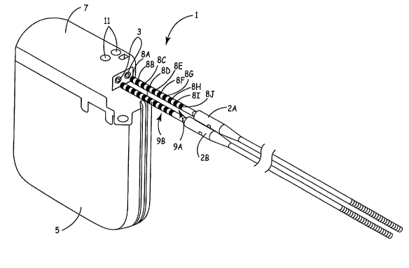
FIG. 1 is a perspective view of an exemplary implantable medical device
capable
of incorporating a connector assembly according to the present invention;
FIG. 2 is an exploded view, in perspective, of one embodiment of a connector
assembly according to the present invention;
FIG. 3 is a plan view of a connector clip utilized in a connector assembly of
the
present invention;
FIG. 4A is a top view of a female member of a housing of a connector assembly,
according to the present invention;
FIG. 4B is a side view of the female member of FIG. 4A;
FIG. 4C is a top view of a female member of a housing of a connector assembly,
according to an alternate embodiment of the present invention;
FIGS. 5A is a perspective view of a female member of a housing of a connector
assembly according to an embodiment of the present invention;
FIG. 5B is a perspective view of the female member of FIG. 5A having a
connector clip positioned thereon;
FIG. 6A is a top view of a male member of a connector assembly, according to
an
embodiment of the present invention;
FIG. 6B is a side view of a male member of a connector assembly, according to
an
embodiment of the present invention;
FIG.6C is a bottom, or exterior, view of a male member of a connector
assembly,
according to an embodiment of the present invention;
FIG. 7A is a perspective view of a male member of a connector assembly,
according to an embodiment of the present invention;
FIG. 7B is a perspective view of the male member of FIG. 7A having a connector
clip positioned therein;
FIG. 8A is a side view of an embodiment of an assembled connector assembly,
according to the present invention;
FIG. 8B is a cross-sectional side view of the assembled connector assembly of
FIG. 8A;
FIG. 8C is a top view of an assembled connector assembly, according to the
present invention;
CA 02534274 2006-O1-30
WO 2005/014104 PCT/US2004/020775
-5-
FIG. 9 is a schematic diagram of a connector assembly according to the present
invention inserted within a connector cavity and having a lead connector
positioned there
through; and
FIG. 10 is a schematic diagram of a connector assembly, according to an
embodiment of the present invention with a lead inserted therein.
The present invention relates to an improved connector assembly for detachably
connecting and retaining the terminal pin of an electrical lead to an
implantable medical
device. The invention utilizes one or more resilient connector clips that are
retained by an
enclosing housing in a partially deflected configuration, or partially loaded
state, such that
a relatively constant force is exerted over the full range of deflection of
the spring. Since
only a small deflection of the spring is necessary to create significant force
of retention on
the inserted terminal pin of the lead, the connector assembly of the present
invention
allows for ease in inserting the terminal pin of the lead and allows for
sufficient force to be
exerted on the terminal pin for optimum retention of the lead without damaging
it.
Furthermore, the connector assembly of the present invention makes efficient
use of the
axial space on the terminal pin, allowing it to be very compact. Axial space
is efficiently
used due to the alignment of the spring contact perpendicular to the inserted
lead. The
connector readily accepts insertion of a terminal pin, without the use of
tools, and applies a
relatively even force through the connector clips to maintain a constant
electrical contact
with the electrical lead that is not subject to varying impedance. The
connector of the
present invention provides the requisite mechanical and electrical connection
functions,
using fewer components and less labor in implementation, yet providing higher
reliability,
durability, resistance to breakdown due to reactions with body fluids, a small
size, and
efficiency in manufacture.
FIG. 1 is a perspective view of an exemplary implantable medical device
capable
of incorporating a connector assembly according to the present invention. As
illustrated in
FIG. l, an exemplary implantable medical device (IMD) 1 incorporating a
connector
assembly according to the present invention includes a hermetically sealed,
biologically
inert housing 5, or "can", that houses IMD circuitry, one or more leads 2A, 2B
that can be
implanted in a patient, and a connector block 7 that receives proximal ends
9A, 9B of
CA 02534274 2006-O1-30
WO 2005/014104 PCT/US2004/020775
-6-
leads 2 to couple leads 2 to the circuitry in housing 5 as leads 2 are
inserted within a
connector port 3 foamed in connector block 7. Once fully inserted within
connector block
7, leads 2 are further fixedly positioned within connector block 7 by
tightening positioning
screws 11 against leads 2.
As illustrated in FIG. 1, the proximal ends 9A and 9B of lead 2A and 2B
include a
plurality of electrical contact areas 8A-8J (collectively contact areas 8).
The present
invention facilitates electrical coupling to one or more of contact areas 8
within connector
block 7. Moreover, the present invention improves such contact for inline
configurations
like FIG. 1 in which a plurality of electrical contact areas 8 are positioned
axially along a
length of leads 2. In particular, the present invention allows size reductions
of contact
areas 8 by improving electrical coupling clips, described below, that
electrically interface
with contact areas 8 inside connector block 7.
IMD 1 corresponds to any medical device that includes medical leads and
circuitry
coupled to the medical leads. By way of example, IMD 1 takes the form of an
implantable
cardiac pacemaker that provides therapeutic stimulation to the heart.
Alternatively, IMD 1
may take the form of an implantable cardioverter or an implantable
defibrillator, or an
implantable cardiac pacemaker-cardioverter-defibrillator. IMD 1 may deliver
pacing,
cardioversion or defibrillation pulses to a patient via electrodes disposed on
distal ends of
leads 2. In other words, leads 2 position electrodes with respect to various
cardiac
locations so that IMD 1 can deliver pulses to the appropriate locations.
Alternatively, IMD 1 corresponds to a patient monitoring device, ox a device
that
integrates monitoring and stimulation features. In those cases, leads 2
include sensors
positioned along distal ends of the respective lead fox sensing patient
conditions. The
sensors include, for example, electrical sensors, electrochemical sensors,
pressure sensors,
flow sensors, acoustic sensors, optical sensors, or the like. In many cases,
IMD 1
performs both sensing and stimulation functions.
In still other applications, IMD 1 corresponds to a neurological device such
as a
deep-brain stimulation device or a spinal cord stimulation device. In those
cases, leads 2
are stereotactically probed into the brain to position electrodes for deep
brain stimulation,
or into the spine for spinal stimulation. In other applications, IMD 1
provides muscular
stimulation therapy, blood sensing functions, and the like. In short, IMD 1
corresponds to
CA 02534274 2006-O1-30
WO 2005/014104 PCT/US2004/020775
any of a wide variety of medical devices that implement leads and circuitry
coupled to the
leads.
As outlined in detail below, connector block 7 of the present invention
incorporates
various components that improve and simplify electrical coupling between leads
2 and
circuitry in housing 5. More specifically, an electrical connector clip
provides a
conductive interface between a medical lead and IMD circuitry. In addition,
various
components that assemble with the connector clip to form at least a portion of
connector
block 7 of IMD 1 are also described. For example, an improved structure having
a
channel for mating with one or more of leads 2 is designed for use with the
connector clip
so that biasing of the connector clip can be achieved prior to insertion of
one or more leads
2 into the channel. As described below, such biasing allows for ease of
insertion of one or
more of leads 2 into the channel of the structure that forms at least part of
connector block
7. In other words, the connector clip defines a desired amount of insertion
force for Iead
pins inserted into connector block 7.
FIG. 2 is an exploded view, in perspective, of one embodiment of a connector
assembly according to the present invention. In the embodiment shown in FIG.
2, a
connector assembly 10 includes one or more connector clips 12 and a housing 13
including a female member 14, and a male member 16. Connector clips 12 are
resilient
and electrically conductive, while housing 13 is sealable and electrically
conductive.
Furthermore, housing 13 provides a structure that retains connector clips 12
in a partially
deflected or partially loaded state and includes a suitable aperture for
insertion of an
electrical lead.
FIG. 3 is a plan view of a connector clip utilized in a connector assembly of
the
present invention. As illustrated in FIG. 3, connector clip 12 is may be used
to provide a
means of retaining a lead (not shown) in place, or both functions together as
a means of
conducting electricity between contact areas 8 of a terminal pin of the lead
and an
electrical apparatus such as a pacemaker. Connector clip 12 is preferably
prepared from a
resilient, high strength, corrosion resistant, biocompatible material, such as
tempered
stainless steel. However, other materials suitable for such applications may
be utilized in
forming connector clip 12 employed in the present invention. Connector clip 12
may be
stamped or cut from a sheet metal strip or cut and formed from wire stock.
Connector clip
CA 02534274 2006-O1-30
WO 2005/014104 PCT/US2004/020775
_8_
12 resembles a wire in form, and may be prepared with a number of differing
cross-
sections, such as circular or oval, for example, where a cross-section is
created by a plane
cutting perpendicular to the long axis of the wire. In an embodiment of the
present
invention, as illustrated in FIG. 3, connector clip 12 has an overall U-shape
with an Timer
surface 144. However, it is noted that the connector clip could be configured
in a variety
of shapes including but not limited to square or diamond shape. 'Connector
clip 12
generally includes a first spring arm 11 and a second spring arm 18, each
including spring
shoulders 20, and a spring back 22 extending between shoulders 20 of first arm
11 and
second arm 18. Spring arms 11 and 18 are preferably bent or project inwards
slightly, so
that the distance between the ends of spring arms 11 and 18 is less than the
distance
between spring shoulders 20 when connector clip 12 is in a non-deflected
state, as
illustrated in FIG. 3.
The dimensions of the various sections of connector clip 12 may vary widely
depending upon the size of the lead and the size of the cavity included in the
electrical
apparatus. However, comiector assembly 10 when included within a pacemaker
device,
for example, will generally include connector clip 12 wherein the distance
between ends
of spring arms 11 and 18 is approximately 0.05 -0.25 inches, the distance
between spring
arm 11/spring shoulder 20 at a widest point is approximately 0.075"-0.30", the
distance
between a line tangential to bottom of spring back 22 and an end of spring arm
118 is
approximately 0.70-0.275 inches, a radius of curve along spring shoulders 20
is
approximately 0.01 ~-0.55 inches and a radius of curve along spring back 22 is
approximately 0.05-0.10 inches". For example, the dimensions for one
embodiment of
connector clip 12 are as follows: a distance between ends of spring arms 11
and 18 is
approximately equal to 0.107 inches; a distance between spring arm 11/spring
shoulder 20
at a widest point is approximately equal to 0.20 inches; a distance between a
line
tangential to a bottom of spring back 22 and an end of spring arm 11 is
approximately
equal to 0.14 inches; a radius of curve along spring shoulder 20 is
approximately equal to
0.035 inches; and a radius of curve along spring back 22 is approximately
equal to 0.073
inches.
In various embodiments of the present invention the distal ends of spring anus
11
and 18 are preferably truncated on their outer edge to form wedges 21, as
illustrated in
CA 02534274 2006-O1-30
WO 2005/014104 PCT/US2004/020775
-9-
FIG. 3. Wedges 21 are positioned on the ends of spring arms 11 and 18 to
provide
clearance between the ends of spring arms 11 and 18 and the sides of housing
13.
Connector clip 12 having the dimensions provided above, when installed in a
suitable
housing (as described below), provides a contact that conforms with the
proposed IS-4
standards, but could be reconfigured for IS-1 standards or other pin diameters
within these
ranges.
As previously mentioned, connector assembly 10 according to the present
invention also includes housing 13 for supporting and retaining connector clip
12. FIG.
4A is a top view of a female member of a housing of a connector assembly,
according to
the present invention. FIG. 4B is a side view of the female member of FIG. 4A.
FIG. 4C
is a top view of a female member of a housing of a connector assembly,
according to an
alternate embodiment of the present invention. As illustrated in FIGS. 4A and
4B,
according to an embodiment of the present invention, female member 14 is an
annular disk
with a wide, circular central aperture 19 centered within the annular disk.
Aperture 19 is
generally of sufficient size to accept proximal ends 9A, 9B of leads 2.
Therefore,
embodiments of the present invention include aperture 19 having a diameter of
approximately 0.05-0.25 inches. In one embodiment, aperture 19 has a diameter
of
approximately 0.10-0.15 inches.
In the embodiment depicted in FIG. 4A, an outer rim of female member 14 forms
an annular shelf 24, with reduced thickness relative to the rest of female
member 14.
When male and female members 14 and 16 are placed together, male member 16
rests
over annular shelf 24 of female member 14, as shown in FIG. 8B. In various
embodiments, annular shelf 24 extends approximately 0.002-.020 inches radially
outward
from an edge of a main surface 26 of female member 14. In some embodiments,
annular
shelf 24 may be a quarter to three quarters the thickness of main surface 26.
Additionally, as illustrated in FIGS. 4A and 4B, female member 14 includes a
bracing ridge 28 positioned along a lower half of female member 14 between
main surface
26 and circular aperture 19. Bracing ridge 28 extends adjacent to an outer
edge of central
aperture 19 and an inner edge of main surface 26 to form a lower portion of
aperture 19.
In various embodiments of the present invention, bracing ridge 28 measures
approximately 0.05-0.25 inches linearly from a first end 15 to a second end
17. In one
CA 02534274 2006-O1-30
WO 2005/014104 PCT/US2004/020775
-10-
embodiment of the present invention, bracing ridge 28 has a relatively flat
arch shape,
with a rectangular cross-section, and may be approximately O.OOS-0.020 inches
thick from
a top portion 125 to a bottom portion 127 in a preferred embodiment as
depicted in FIGS.
4A and 4B. Top portion 27 of bracing ridge 28 extends outward from main
surface 26 to
deflect spring arms 11 and 18 so that they remain in a partially loaded or
deflected
position when connector clip 12 is positioned within female member 14. Thus,
when this
embodiment of female member 14 is used to hold connector clip 12 with the
dimensions
described above, bracing ridge 28 deflects spring arms 11 and 18 from a
resting separation
of approximately 0.005 to 0.020 inches when in the non-deflected position, for
an overall
deflection of approximately 0.006-0.021 inches. It is noted that the
dimensions identified
in this embodiment may be increased or decreased depending upon the desired
design of
the comiector in view of the size of the terminal pin of the lead.
Furthermore, it is noted
that in another embodiment of the present invention, illustrated in FIG. 4C,
bracing ridge
28 may alternatively include two bracing pegs 129 extending outward from main
surface
1 S 26 for separating spring arms 11 and 18 and placing connector clip 12 in a
partially loaded
or deflected position.
Depicted in FIGS. 4A and 4B, opposite from bracing ridge 28 and within female
member 14, is a support ridge 30. As with bracing ridge 28, support ridge 30
may be a
relatively flat arch that runs along the inner edge of main surface 26 and
adjacent to the
outer edge of circular aperture 19. In certain embodiments of the present
invention,
support ridge 30 extends outward from main surface 26 to approximately the
same height
as bracing ridge 28, but has a length of approximately one half of that of
bracing ridge 28,
so that the linear measurement from a first end 35 to a second end 37 of ridge
30 is
approximately 0.01-0.15 inches. Alternatively, as depicted in FIG. 4C, support
ridge 30
may include support pegs 131 extending outward from main surface 26, similar
to bracing
ridge 28, as described above. Support ridge 30 serves to anchor connector clip
12 in place
by resting within the interior of spring back 22. Preferably, a cut out
portion 39 formed by
a side wall 41 between support ridge 30 and an outer edge 43 of main surface
26 is just
enough to accommodate the width of connector clip 12.
The ends of bracing ridge 28 are preferably flat so that the ends of the
bracing
ridge 28 will lie flat upon inner surface 44 of the inserted spring arms 11
and 18 to provide
CA 02534274 2006-O1-30
WO 2005/014104 PCT/US2004/020775
-11-
secure and stable support. FIGS. 5A is a perspective view of a female member
of a
housing of a connector assembly according to an embodiment of the present
invention.
FIG. 5B is a perspective view of the female member of FIG. 5A having a
connector clip
positioned thereon. FIG. 5A shows female member 14 without connector clip 12,
while
FIG. 5B shows female member 14 with a properly positioned connector clip 12,
with
support ridge 30 positioned within spring back 22, and spring arms 11 and 18
held open in
a partially deflected state by bracing ridge 28. A portion of each of spring
arms 11 and 18
projects over circular aperture 19 when connector clip 12 is positioned within
the housing,
to provide contact points for an inserted lead. It is noted that connector
clip 12 may be
spot welded to help retain connector clip 12 in place, or otherwise attached
to the housing.
According to an embodiment of the present invention, housing 13 also includes
a
male member 16 that is operably connected to female member I4. FIG. 6A is a
top view
of a male member of a connector assembly, according to an embodiment of the
present
invention. FIG. 6B is a side view of a male member of a connector assembly,
according to
an embodiment of the present invention. FIG.6C is a bottom, or exterior, view
of a male
member of a connector assembly, according to an embodiment of the present
invention.
As illustrated in FIGS. 6A-6C, according to one embodiment of the present
invention,
male member 16 is an annular disk with a wide, circular aperture 33 centered
within the
annular disk. In various embodiments, central aperture 33 has a diameter of
approximately 0.05-0.25 inches, similar to that found in female member 14.
Male member
16 is similar to female member 14, in that male member I6 includes main
surface 26,
supporting bracing ridge 28 and support ridge 30 running along and adjacent to
central
aperture 33, that have essentially the same dimensions and functions as those
described
above. Alternatively, bracing ridge 28 and support ridge 30 may include
bracing pegs and
support pegs (not shown) similar to those described above in the description
of female
member 14. Female member 14 includes annular shelf 24, and male member 16
includes
a cylindrical rim 32 that extends outward along and perpendicular to the outer
edge of
main surface 26 of male member 16. Cylindrical rim 32 forms a short cylinder
that
encloses the components of housing 13 when the male and female members are
placed
together. In various embodiments of the present invention cylindrical rim 32
has an outer
diameter of approximately 0.10-0.30 inches and an inner diameter of 0.05-0.35
inches,
CA 02534274 2006-O1-30
WO 2005/014104 PCT/US2004/020775
-12-
such that cylindrical rim 32 fits snugly onto annular shelf 24 of female
member 14 when
the two members 14 and 16 are placed together.
FIG. 7A is a perspective view of a male member of a connector assembly,
according to an embodiment of the present invention. FIG. 7B is a perspective
view of the
male member of FIG. 7A having a connector clip positioned therein. Again
connector clip
12 may be spot welded to help retain connector clip 12 in place or otherwise
attach
connector clip 12 to male member 16. As can be seen most clearly in FIG. 7B, a
portion
45 of each of spring arms 11 and 18 projects over and within circular aperture
33 when
connector clip 12 is positioned on male member 16 with support ridge 30
positioned
within spring back 22 and spring arms 11 and 18 positioned in a partially
deflected
position by bracing ridge 28, so that portion 45 forms a contact point 34 that
comes in
contact with a lead (not shown) subsequently inserted within comlector
assembly 10.
As noted above, male member 16 and female member 14 are designed so that male
member 16 and female member 14 fit together to create single housing 13
enclosing one
or more connector clips 12. FIG. 8A is a side view of an embodiment of an
assembled
connector assembly, according to the present invention. From the side view,
cylindrical
rim 32 of male member 16 is visible. The only portion of female member 14 that
is visible
in FIG. 8A is the edge of annular shelf 24. FIG. 8B is a cross-sectional side
view of the
assembled connector assembly of FIG. 8A. As illustrated in FIG. 8B, within
connector
assembly 10, the cross-section of one connector clip 12 cuts through spring
arms 118 of
connector clip 12 in male member 16, while the cross section of the other
connector clip
12 mounted in female member 14 shows the midpoint of spring back 22. FIGS. 8A
and
8B illustrate that the assembled housing 13 creates a barrier against leakage
of fluid
through the connector into the apparatus. Finally, FIG. 8C is a top view of an
assembled
connector assembly, according to the present invention. In FIG. 8C, contact
points 34 of
connector clip 12 for engaging against a lead (not shown) inserted within an
assembled
connector assembly 10 are visible where connector clips 12 extend into
aperture 19
created by housing 13, with aperture 19 of female portion 14 and aperture 33
of male
portion 16 overlapping to form an opening 47 for receiving a lead with springs
arms 11
and 18 of connector clip 12 in the partially deflected position. When two
connector clips
12 are juxtaposed in a perpendicular fashion, as shown in FIG. 1, connector
clips 12 form
CA 02534274 2006-O1-30
WO 2005/014104 PCT/US2004/020775
-13-
a square wherein the midpoint of each side of the square forms a potential
contact point
34. While not required to practice the present invention, an embodiment using
two,
perpendicularly-placed connector clips 12 provides four contact points 34
along the four
points of the compass. The placement of two perpendicular connector clips 12
helps to
securely contact and retain the contact areas of a lead, as deviation of the
lead in any
particular direction will naturally be countered by the tension within the
connector clips
12. As a result, the comiector of the lead may be oriented in any direction
around its
central axis and function equally well.
Male member 16 and female member 14 of the present invention are preferably
prepared from a high strength, corrosion resistant, biocompatible material,
such as
tempered stainless steel. However, any conductive biocompatible material may
be utilized
to prepare housing 13 of the present invention. As previously suggested,
housing serves to
position connector clips 12 to be in a partially loaded position thereby
providing for more
ease in inserting the lead. Generally, housing 13 also serves to conduct
electricity from
connector clips 12 to another conductor (not shown), which is connected with
the
electrical apparatus, such as a pacemaker. FIG. 9 is a schematic diagram of a
connector
assembly according to the present invention inserted within a connector cavity
and having
a lead connector positioned there through. As illustrated in FIG. 9, housing
13 also allows
connector assembly 10 to be properly positioned within a connector cavity 136,
as
illustrated in FIG. 9. While the FIGS. 1-10 illustrate a cylindrical, disc-
shaped connector
with a circular aperture, neither of these structural features are required
for the present
invention. For example, if it were desirable to attach a square lead, a square
central
aperture would be preferred. Furthermore, the overall shape of the connector
assembly 10
may deviate from the cylindrical disc illustrated in FIGS. 1-10 without
compromising its
function.
Prior to use of the present invention, one or more connector clips 12 are
placed
within housing 13 and over support ridge 30 and bracing ridge 28 of one or
both of female
member 14 and male member 16 so that bracing ridge 28 deflects connector clips
12 in the
partially deflected position, with arms 118 extending within aperture 19 (FIG.
7B), or if
two clips are utilized, within both aperture 19 and aperture 33 (FIG. 8C).
Prior to such
placement, connector clips 12 are in a relaxed non-deflected state, in which
the arms bend
CA 02534274 2006-O1-30
WO 2005/014104 PCT/US2004/020775
-14-
slightly inwards, as shown in FIG. 2. After placement, spring arms 11 and 18
of connector
clips 12 are partially deflected by bracing ridge 28 thereby placing connector
clip 12 in a
partially loaded or deflected state so as to reduce the force required to
insert the lead into
connector assembly 10, with portion 45 of each spring arm 118 projecting over
circular
aperture 19 and circular aperture 33. After such placement of connector clip
12, connecter
assembly 10 is ready to receive and retain an electrical lead.
According to the present invention, the connection of lead 2A or 2B to an
electrical
device may be accomplished by utilizing one or more of connector assemblies 10
of the
present invention. As illustrated in FIG. 9, several of connector assemblies
10 of the
present invention may be utilized within a connector cavity 36 forming a
portion of
connector block 7 that conforms with international standard IS-4 requirements.
Use of
several connector assemblies 10 provide a greater number of contact points 34,
resulting in
an even more secure and reliable connection to contact areas 8 of electrical
lead 2A or 2B.
Whether one or more connector assemblies 10 of the present invention is
utilized,
each connector assembly 10 is positioned within connector cavity 36 of a
connector region
where connector assembly 10 is coupled with wires or other suitable means such
that
connector assembly 10 is in electrical communication with an electrical source
(not
shown). The connector region is normally constructed from plastic, silastic,
or other
electrically non-conductive material, and serves to position connector
assembly 10 while
preventing undesirable leakage of body fluids or eleetric current. A wire (not
shown)
generally runs from connector assembly 10 to the working portion of the
apparatus that
provides transmission of electrical current, such as electrical pulses.
Examples of
apparatuses for emitting electrical pulses for use with the present invention
may be single
or dual chamber pacemakers, antiarrhythmia pacers, defibrillators,
cardiomyoplasty
stimulators, neurostimulators, and other such devices which emit electrical
impulses.
FIG. 10 is a schematic diagram of a connector assembly, according to an
embodiment of the present invention with a lead inserted therein. As
illustrated in FIGS. 9
and 10, when a physician or other user of the device wishes to establish an
electrical
connection between electrical lead 2A or 2B and the electrical source, the
physician need
merely place contact areas 8 of electric lead 2A or 2B within connector cavity
36. Contact
area 8A or 8B is then urged into connector cavity 36, where contact areas 8
comes in
CA 02534274 2006-O1-30
WO 2005/014104 PCT/US2004/020775
-15-
contact with and pushes against contact points 34 of connector clip 12 of
connector
assembly 10 of the present invention. As lead 2A or 2B is inserted within
connector
cavity 36 of connector block 7, lead 2A or 2B advances through apertures 19
and 33,
causing spring arms 11 and 18 of connector clip 12 to be deflected yet further
from the
partially deflected position, engaged against bracing ridge 28 to extend
outward from and
no longer engaged against ends 15 and 17 of bracing ridge 28, placing
connector clip 12 in
a fully deflected position. As a result, the spring force of connector clip 12
is transferred
from being engaged against bracing ridge 28 to being against contact areas 8
of lead 2A or
2B. In this way, portion 45 of each spring arm 11 and 18 is engaged against
contact areas
8, causing the spring force to be applied by spring arms 11 and 18 against
inserted contact
areas 8, creating a secure electrical connection at contact points 34. Once
fully inserted,
electrical lead 2A or 2B is in a loaded state and will remain in place,
connected to the
electrical source.
Lead 2A or 2B may optionally be provided with grooves (not shown) positioned
at
expected contact points 34 that serve to further secure lead 2A or 2B when
connector clip
12 expands into the space of the groove. Also illustrated in FIG. 9 are
several sealing
devices 42, which help assure that body fluids do not leak into and possibly
clog and/or
corrode connector assembly 10, contact areas 8 and the electrical apparatus.
It is apparent from the foregoing discussion that the embodiments of the
present
invention illustrated in FIGS. 1-10 provides an improved comiector assembly 10
for
detachably connecting contact areas 8 of electrical lead 2A or 2B to an
electrical
apparatus. Since connector clips 12 are retained by housing 13 in a partially
deflected
configuration, a constant force is exerted over the range of deflection of
connector clip 12.
Furthermore, since only a small deflection is necessary to create a
significant force of
retention, connector assembly 10 makes efficient use of the axial space on
contact areas 8,
allowing it to be very compact. Connector assembly 10 readily accepts
insertion of
contact areas 8, without the use of tools, and applies even force through
connector clips 12
to maintain a constant electrical contact with electrical lead 140 that is not
subject to
varying impedance.
Although the invention has been described with reference to particular
embodiments, it is to be understood that such embodiments are merely
illustrative of the
CA 02534274 2006-O1-30
WO 2005/014104 PCT/US2004/020775
-16-
application of the principles of the invention. Numerous modifications may be
made
therein, and other arrangements may be devised, without departing from the
true scope and
spirit of the invention.