Note: Descriptions are shown in the official language in which they were submitted.
WO 2005/021319
CA 02534770 2006-02-03
PCT/US2004/027894
LOCKING MECHANISM FOR SEAT TRACK ASSEMBLY BACKGROUND OF THE INVENTION
1. Field of the Invention
The present invention relates to a track assembly for a seat assembly of an
automotive
vehicle. More particularly, the present invention relates to a seat track
assembly having a
locking mechanism with a plurality of locking fingers movable between a locked
position for
interlocking upper and lower tracks of the seat track assembly and an unlocked
position
disengaged from the tracks to allow sliding movement therebetween.
2. Description of the Related Art
Automotive vehicles include seat assemblies for supporting occupants above a
floor
in the vehicle. Typically, a seat assembly includes a track assembly that is
operatively
coupled between the seat assembly and the floor of the vehicle and allows
selective forward
and rearward movement of the seat assembly relative to the floor. The track
assembly
typically includes a lower track and an upper track slidably engaged
therewith, which allows
the sliding movement of the seat assembly relative to the floor. Latch or
locking mechanisms
are commonly known in the art for interlocking the upper and lower tracks to
prevent the
forward and rearward movement of the seat assembly relative to the floor.
One type of locking mechanism known in the art utilizes a plurality of locking
pawls
or pins that engage one or more slots or apertures on the lower track to
interlock the upper
and lower tracks. Examples of these types of locking mechanisms are disclosed
in German
patents DE 19735030A1, DE 29700866U1 and in United States Patents 5,596,910
and
5,564,315.
1
WO 2005/021319
CA 02534770 2006-02-03
PCT/US2004/027894
These type of locking mechanisms do not allow "infinite" or "positive"
engagement
between the upper and lower tracks. That is, the upper track is not lockable
relative to the
lower track in any position. Rather, the upper track is adjustable relative to
the lower tracks
in predetermined increments of adjustment, as the occupant of the seat
assembly must
properly position the upper track along the lower track until at least one of
the pins is aligned
with the aperture to engage therewith and interlock the upper and lower
tracks. Further, such
locking mechanisms typically allow a predetermined amount of play or chuck
between the
upper and lower tracks.
It remains desirable to provide a seat track assembly having a locking
mechanism that
provides a minimal increment of adjustment and at the same time minimizes
chuck between
the upper and lower tracks.
According to one aspect of the invention, a locking mechanism is provided for
SUMMARY OF THE INVENTION
selectively interlocking upper and lower tracks of a seat track assembly. The
locking
mechanism includes a pin carrier having a body and at least one arm having an
intermediate
portion extending between a proximal end fixedly secured to the body and a
distal end. The
distal end of the arm has a wider profile than the intermediate portion to
define a stop edge.
The distal end has a bore formed therein. A mounting plate is adapted to be
fixedly secured
to the upper track. The mounting plate has at least one slot having adjacent
narrow and wide
portions defining a stop surface due to the difference in size between the
narrow and wide
portions. The wide portion is adapted to receive the distal end of the arm
therethrough during
assembly of the pin carrier and the mounting plate. The narrow portion is
adapted to slidably
receive the intermediate portion of the arm therethrough for selective sliding
movement of
2
CA 02534770 2006-02-03
WO 2005/021319 PCT/US2004/027894
the pin carrier relative to the mounting plate. The stop surface is engagable
with the stop
edge of the pin carrier to prevent removal of the arm from the slot. A
plurality of pins are
slidably coupled to both the pin carrier and the mounting plate for movement
in and out of
locking engagement with the upper and lower tracks during corresponding
movement of the
pin carrier relative to the mounting plate. Each of the pins includes a raised
step defining
opposite first and second abutment surfaces. The first abutment surface is
engagable with the
body of the pin carrier such that the plurality of pins moves with the pin
carrier relative to the
mounting plate.
The locking mechanism also includes a plurality of coil springs each energized
between the second abutment surface of at least one of the plurality of pins
and the mounting
plate for continuously biasing apart the pin carrier and the mounting plate.
BRIEF DESCRIPTION OF THE DRAWINGS
Advantages of the present invention will be readily appreciated as the same
becomes
better understood by reference to the following detailed description when
considered in
connection with the accompanying drawings wherein:
Figure 1 is a perspective view of a seat track assembly according to one
embodiment
of the invention;
Figure 2 is a cross sectional view of the seat track assembly and a locking
mechanism
in the seat track assembly according to one embodiment of the invention;
Figure 3 is an enlarged side view of the seat track assembly;
Figure 4 is an exploded perspective view of the seat track assembly and the
locking
mechanism;
Figure 5 is an exploded perspective view of the locking mechanism;
3
CA 02534770 2006-02-03
WO 2005/021319 PCT/US2004/027894
Figure 6 is a perspective view of a pin carrier in the locking mechanism
according to
one embodiment of the invention;
Figure 7 is a perspective view of a pin in the locking mechanism according to
one
embodiment of the invention;
Figures 8a-8f are schematic views of the sizing and spacing relationship
between the
pins and locking windows in the locking mechanism according to one embodiment
of the
invention;
Figure 9 is a cross sectional view of the seat track assembly and the locking
mechanism according to an alternative embodiment of the invention; and
Figure 10 is a schematic view of the locking mechanism according to the
alternative
embodiment of Figure 9.
DETAILED DESCRIPTION OF THE PREFERRED EMBODIMENTS
Referring to Figures 1 through 7, a track assembly for a seat assembly (not
shown) of
an automotive vehicle is generally indicated at 10. The track assembly 10
includes a lower
track 12 and an upper track 14. The lower track 12 is adapted to be fixedly
secured to a floor
in the vehicle. The upper track 14 is adapted to be fixedly secured to a
bottom of a seat
cushion (not shown) of the seat assembly. The upper track 14 is slidably
coupled to the lower
track 12 to allow selective forward and rearward movement of the seat cushion
among a
plurality of seating positions relative to the floor. Described in greater
detail below, the track
assembly 10 includes a latch or locking mechanism 80 for selectively
interlocking the lower
12 and upper 14 tracks to releasably lock the seat cushion in any one of the
plurality of
seating positions.
Referring specifically to Figures 1 and 2, the lower track 12 has a generally
U-shaped
cross section defined by a lower web 20 extending laterally between generally
upright inner
4
WO 2005/021319 CA 02534770 2006-02-03PCT/US2004/027894
22 and outer 24 walls. Each of the inner 22 and outer 24 walls includes hooked
portions 26,
28, respectively, that are turned laterally inwardly. Each of the hooked
portions 26, 28
defines an upper bearing surface 30, 32. An outer flange 36 protrudes
downwardly from the
hooked portion 28 of the outer wall 24 toward the lower web 20. The outer
flange 36 is
generally parallel to and spaced apart from the outer wall 24.
The upper track 14 has a generally U-shaped cross section defined by an upper
web
40 that extends laterally between generally upright first 42 and second 44
walls. Each of the
first 42 and second 44 walls includes hooked ends 46, 48 that are turned
laterally outwardly.
The hooked end 46 of the first wall 42 includes a first distal wall 58 that
extends upwardly
toward the hooked portion 26 of the inner wall 22 of the lower track 12. A
second distal wall
60 extends upwardly from the hooked end 48 of the second wall 44 toward the
hooked
portion 28 of the outer wall 24, such that the outer flange 36 is disposed
between the second
wall 44 and the second distal wall 60. The second distal wall 60 includes an
outwardly flared
or bent end 61. Arcuate lower bearing surfaces 50, 52 are defined by the
hooked end 46 of
the first wall 42 and by the bent end 61 of the second distal wall 60,
respectively. Each of the
lower bearing surfaces 50, 52 opposes the respective upper bearing surfaces
30, 32 to define
generally cylindrical bearing spaces 54, 56 therebetween. Preferably, the
lower bearing
surfaces 50, 52 are angled inwardly to promote centering of the upper track 14
relative to the
lower track 12.
A plurality of ball bearings 62 is disposed in the bearing spaces 54, 56. A
plurality of
roller bearings 64 is supported between the hooked ends 46, 48 of the upper
track 14 and the
lower web 20 of the lower track 12. The ball bearings 62 and roller bearings
64 reduce
friction during sliding adjustment of the upper track 14 relative to the lower
track 12.
Preferably, the ball bearings 62 and roller bearings 64 are offset
longitudinally to allow
5
CA 02534770 2006-02-03
WO 2005/021319 PCT/US2004/027894
elastic deflection between and prevent binding of the lower 12 and upper 14
tracks under
heavy loads.
Referring to Figures 2-4, a generally rectangular cutout 68 is formed in and
extends
longitudinally along the first wall 42 of the upper track 14. A plurality of
first apertures 70 is
formed in and disposed longitudinally along the second wall 44 of the upper
track 14. The
first apertures 70 are evenly spaced apart and aligned opposite with the
cutout 68. A plurality
of second apertures 72 is formed in and disposed longitudinally along the
second distal wall
60 of the upper track 14. The first 70 and second 72 apertures are generally
aligned. A
plurality of locking windows 74 is formed in and disposed longitudinally along
the outer
flange 36 of the lower track 12.
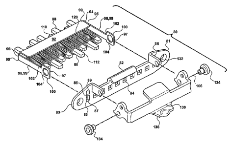
Referring to Figures 1-5, the locking mechanism 80 is operatively coupled
between
the lower 12 and upper 14 tracks for releasably interlocking the lower 12 and
upper 14 tracks.
More specifically, the locking mechanism 80 includes a mounting plate 82
adapted to be
fixedly secured to the first wall 42 of the upper track 14. The mounting plate
82 extends
between first 81 and second 83 ends. A pair of slots 86 are formed in the
mounting plate 82,
each disposed on one of the first 81 and second 83 ends of the mounting plate
82. Each slot
86 includes adjacent wide 85 and narrow 87 portions. The narrow portion 87 of
the slot 86
defines a stop surface 89. A plurality of third apertures 84 is formed between
the slots 86 in
the mounting plate 82. The third apertures 84 are generally aligned with the
first 70 and
second 72 apertures when the mounting plate 82 is fixedly secured to the upper
track 14.
The locking mechanism 80 further includes a plurality of pins 88 and a pin
carrier 90.
The pin carrier 90 includes a body 92 extending between first 94 and second 96
ends. As
shown in Figure 6, a plurality of fourth apertures 93 are formed between the
first 94 and
second 96 ends of the body 92. The fourth apertures 93 are generally aligned
with first 70,
6
WO 2005/021319 CA 02534770 2006-02-03PCT/US2004/027894
second 72 and third 84 apertures for slidably supporting each of the plurality
of pins 88
therein.
An arm 98 extends outwardly from each of the first 94 and second 96 ends of
the
body 92. Each arm 98 includes a proximal end 95 fixedly secured to one of the
first 94 and
second 96 ends of the body 92, a distal end 97, and an intermediate section 99
extending
therebetween. Each arm 98 includes a wide section 100 defined at each distal
end 97 thereof.
The wide section 100 has a wider profile than the intermediate portion 99. The
wide section
100 of the arm 98 is sized to pass through the wide portion 85 of the slot 86
to allow
assembly of the pin carrier 90 and the mounting plate 82. The intermediate
section 99 of the
arm 98 is sized to slidably engage the narrow portion 87 of the slot 86 after
assembly of the
pin carrier 90 and the mounting plate 82. A stop edge 102 is defined in the
arm 98 due to the
difference in width between the wide 100 and intermediate 99 sections. The
stop edge 102
engages the stop surface 89 of the mounting plate 82 to prevent removal of the
arms 98 from
the slots 86. A bore 104 is formed in each wide section 100. The bores 104 are
coaxial and
define a pivot axis 106. In assembly, the arms 98 are slidably engaged within
the narrow
portions 87 of the slots 86 for lateral displacement of the pin carrier 90
between the first 42
and second 44 walls of the upper track 14.
As best shown in Figure 7, each of the pins 88 extends longitudinally between
opposite first 110 and second 112 ends. Preferably, the first end 110 of each
pin 88 is tapered
to facilitate movement of each pin 88 in and out of engagement with the second
aperture 72.
Each of the pins 88 includes a raised step 114 disposed between the first 110
and second 112
ends. Each raised step 114 defines first 116 and second 118 abutment edges.
The first 116
and second 118 abutment edges face the first 110 and second 112 ends,
respectively. Each
first end 110 of each of the pins 88 is slidably supported in one of the
fourth apertures 93 of
the pin carrier 90. The first abutment edges 116 are engagable with the body
92 of the pin
7
WO 2005/021319 CA 02534770 2006-02-03PCT/US2004/027894
carrier 90 to prevent the pins 88 from sliding completely through the fourth
apertures 93.
Similarly, each second end 112 of each of the pins 88 is slidably engaged to
one of the third
apertures 84 of the mounting plate 82.
The locking mechanism 80 also includes a plurality of coil springs 120. Each
of the
coil springs 120 is coaxially supported on one of the pins 88 and compressed
between the
second abutment edge 118 and the mounting plate 82. While the first abutment
edges 116 of
the pins 88 are engaged with the body 92 of the pin carrier 90, the coil
springs 120 bias the
pin carrier 90 apart from the mounting plate 82. Engagement between the stop
edges 102 and
the stop surfaces 89 prevents the arms 98 from exiting the slots 86 due to the
force applied by
the coil springs 120. Thus, the coil springs 120 are continuously compressed
between the
mounting plate 82 and the body 92 of the pin carrier 90.
Referring back to Figures 1 through 5, the locking mechanism 80 also includes
a lever
actuator 130. The lever actuator 130 is pivotally coupled to the mounting
plate 82 for
movement about a pivot axis 132 between unlocked and locked positions. Pivot
pins 134
extend through the bores 104 of the arms 98 and pivotally interconnect the
lever actuator 130
to the mounting plate 82, so that the pin carrier 90 moves laterally between
the first 42 and
second 44 walls in response to the pivotal movement of the lever actuator 130
between the
locked and unlocked positions, respectively. Specifically, in the locked
position, the stop
edges 102 of the arms 98 are held against the stop edges 89 of the mounting
plate 82 by the
compression of the coil springs 120. Movement of the lever actuator 130 about
the lever
pivot axis 132 toward the unlocked position causes the pin carrier 90 to move
toward the
mounting plate 82. The pins 88 move with the pin carrier 90. The arms 98 slide
within the
narrow portions 87 of the slots 86 and the second ends 112 of the pins 88
slide within the
third apertures 84 to accommodate the movement of the pin carrier 90 relative
the mounting
8
CA 02534770 2006-02-03
WO 2005/021319 PCT/US2004/027894
plate 82. The pins 88 move toward the mounting plate 82 with the pin carrier
90 as the body
92 of the pin carrier 90 engages the first abutment edges 116 of the pins 88.
As shown in Figure 1, the lever actuator 130 includes a cam flange 136. A
"towel
bar" or handle 138 is pivotally coupled to the upper track 14 by pivot pin
139. The handle
138 engages the cam flange 136 during manual actuation of the handle 138 to
facilitate
movement of the lever actuator 130 between the locked and unlocked positions.
As shown in Figure 4, the locking mechanism 80 can be pre-assembled prior to
installation to the lower 12 and upper 14 tracks. After the locking mechanism
80 has been
assembled, the mounting plate 82 is fixedly secured to the upper track 14 so
that the pins 88
are aligned with the cutout 68 in the first wall 42. The second ends 112 of
the pins 88 can
pass through the cutout 68 to accommodate the movement of the pin carrier 90
relative to the
mounting plate 82. All of the pins 88 are slidably supported by the first
apertures 70 of the
upper track 14 as the pins 88 are moved in and out of the locking windows 74
by the pivotal
movement of the lever actuator 130 between the locked and unlocked positions,
respectively.
Preferably, the pins 88 and locking windows 74 are sized and spaced so that,
in the locked
position, at least three out of five of the pins 88 are forced by the coil
springs 120 through
three adjacent locking windows 74 to prevent forward and rearward movement of
the upper
track 14 relative to the lower track 12. Most preferably, the pins 88 in the
locked position are
received through the locking windows 74 and supported by the first 70 and
second 72
apertures, so that the pins 88 are in a double shearing condition under
loading of the upper
track 14 relative to the lower track 12. More specifically, with the pins 88
extending through
the locking windows 74 in the lower track 12 and extending through each of the
first 70 and
second 72 apertures of the upper track 14, any forces exerted upon the seat
assembly and
passing through the pins 88 are transferred through and supported by the outer
flange 36 of
the lower track 12 and both the second wall 44 and second distal wall 60 of
the upper track
9
CA 02534770 2006-02-03
WO 2005/021319 PCT/US2004/027894
14 to provide extra load support and secure locking between the lower 12 and
upper 14
tracks.
The sizing and spacing of the pins 88 and locking windows 74 is best shown in
Figures 8a through 8f. Each of the Figures 8b through 8f represent successive
increments of
travel of the upper track 14 relative to the lower track 12, after that which
is shown in Figure
8a. For example, Figure 8b represents one increment of travel and Figure 8f
represents five
increments of travel from that shown in Figure 8a. The distance of one
increment of
adjustment is I. The pins 88 are represented by circles labeled 1 through 5.
Solid circles
indicate pins 88 that are engaged with locking windows 74. Each of the pins 88
has a pin
width t. The spacing between adjacent pins 88 is S. The pitch or distance
between the
centers of adjacent pins 88 is Pt. The pitch or distance between leading edges
of adjacent
locking windows 74 is P. The width of land or distance between adjacent
locking windows
74 is L. Each locking window 74 has a window width W. To ensure that at least
three of
five pins 88 will engage the locking windows 74, the sizing and spacing of the
pins 88 and
locking windows 74 is established by the following equations in terms of
increment I and pin
width t.
Pt = 31;
Pw = 51;
W = 21 + t;
L = 3I ¨t; and
S = Pt¨t.
In the preferred embodiment, the increment of adjustment I is 2.5 mm; the
width t of
each pin 88 is 3.5 mm; the pitch Pt of the pins 88 is 7.5 mm; the pitch Pw of
the locking
windows 74 is 12.5 mm; the width of the land L between adjacent locking
windows 74 is 4.0
mm; and the width W of each locking window 74 is 8.5 mm.
10
WO 2005/021319 CA 02534770 2006-02-03PCT/US2004/027894
In operation, the upper track 14 can be adjusted relative to the lower track
12 by
unlocking the locking mechanism 80. The lever actuator 130 is rotated about
the pivot axis
132 to the unlocked position by manual actuation of the handle 138. The pin
carrier 90 is
pulled laterally toward the mounting plate 82 against the force of the coil
springs 120 as the
lever actuator 130 rotates toward the unlocked position. The body 92 of the
pin carrier 90
engages the first abutment edges 116 of the pins 88 so that the pins 88 are
displaced with the
pin carrier 90 toward the mounting plate 82. When the second ends 112 of the
pins 88 have
exited the locking windows 74, the upper track 14 is forwardly or rearwardly
slidable relative
to the lower track 12. The lever actuator 130 must be manually maintained in
the unlocked
position while the upper track 14 is adjusted relative to the lower track 12.
After the upper track 14 has been adjusted to a desired position, the handle
138 is
released to allow the lever actuator 130 to return to the locked position. The
coil springs 120,
compressed between the mounting plate 82 and the second abutment edges 118,
force the
pins 88 and the pin carrier 90 away from the mounting plate 82. The stop edge
102 of the pin
carrier 90 engages the stop surface 89 of the mounting plate 82 to prevent
further lateral
movement of the pin carrier 90. The pins 88 are continuously forced toward
engagement
with the locking windows 74 and the second support apertures 72. As described
above, at
least three pins 88 engage the locking windows 74 and the second support
apertures 72 to
lock the upper track 14 in the desired position relative to the lower track
12.
Referring to Figures 9 and 10, an alternative embodiment of the invention is
shown,
wherein elements of the alternative embodiment similar to those in the first
embodiment are
indicated by primed reference characters. The pins 88' are slidably supported
in the first 70',
second 72', third 84' and fourth 93' support apertures for movement in and out
of locking
engagement with the locking windows 74'. The first ends 112' of the pins 88'
are tapered to
facilitate movement of the pins 88 in and out of the locking windows 74' and
the second
11
CA 02534770 2012-07-16
apertures 72'. The second apertures 72' are offset in a longitudinal sense
relative to the
first apertures 70'. The offset of the second apertures 72' relative to the
first apertures
70' causes the pins 88 in the locked position to rotate and interfere or jam
against the
outer flange 36 of the lower track 12. Further, second apertures 72' on
opposite sides
of a reference plane Z, indicated by a dashed line, are offset in opposite
directions with
respect to the reference plane Z. As a result, at least two pins 88 in the
locked position
are rotated in opposite directions to minimize chuck or play of the upper
track 14
relative to the lower track 12. For example, pin numbers 1 and 5 are rotated
in opposite
directions against the outer flange 36 at opposite ends of the respective
second
apertures 72' to minimize play between the lower 12 and upper 14 tracks.
It should be appreciated by those skilled in the art that while eight pins
engaging
five locking windows are shown in Figures 3, 5, 6 and 9, the invention
requires only at
least five pins for engaging three locking window. Additional pins and locking
windows are utilized to enhance the strength and anti-chuck characteristics of
the
locking mechanism.
It should be appreciated that the foregoing description is illustrative in
nature
and that the present invention includes modifications, changes, and
equivalents thereof,
without departure from the scope of the invention.
12