Note: Descriptions are shown in the official language in which they were submitted.
CA 02534859 2006-02-06
WO 2005/017498 PCT/US2004/024987
TITLE: LIGHT EMITTING DIODE BASED MEASUREMENT SYSTEMS
BACKGROUND OF THE INVENTION
Field of the Invention
This invention generally relates to light emitting diode based measurement
systems. Certain embodiments
relate to a measurement system that includes one or more arrays of light
emitting diodes arranged along a flow path
of microspheres or other fluorescence emitting samples.
2. Description of the Related Art
Generally, flow cytometers provide measurements of fluorescence intensity of
laser excited polystyrene
beads or cells as they pass linearly through a flow chamber. However, flow
cytometers can also be used to provide
measurements of one or more properties of other particles. Some systems are
configured to perform measurements
on the level of light scattered by particles at 90 or 180 degrees to the
excitation source, two or more measurements
of fluorescence used to determine classification, which is the particle
"identity," and additional fluorescence
measurements known as "reporters," typically used to quantify chemical
reactions of interest. Each of the
fluorescent measurements is made at different wavelengths.
One excitation laser commonly used in flow cytometers is a 532 nm solid-state
laser. Such a laser tends to
have a relatively large beam diameter (e.g., about 0.3 mm). A lens system may
be used to reduce the beam diameter
of the laser to an elliptical spot having lateral dimensions of about 75 ~,m
by about 25 Vim. The elliptical spot lies
within an optical sensor's detection window. There are, however, several
disadvantages to the 532 nm laser. For
example, the 532 nm laser is quite expensive (e.g., about $5,500 each),
consumes significant electrical power, and
generates a substantial amount of heat.
Another laser that is used in commercially available flow cytometers is an
argon ion 488 nm laser. There
are, however, also several disadvantages to this laser. For example, it is
relatively large (e.g., occupying several
cubic feet), requires a massive power supply, and needs constant forced air
cooling to maintain stability. There are
other smaller and less expensive lasers that are commercially available.
However, these lasers are generally
unsuitable for flow cytometry. For example, dye lasers may burn out too
quickly to be used as suitable light sources
in a flow cytometer based measurement system. In addition, He-Cd lasers may be
too noisy for flow cytometer
measurements.
Furthermore, he beam profile of a laser diode may be relatively uneven
compared to that of a standard
argon ion laser. The unevenness presents a significant obstacle for flow
analyzers because fluorescence
measurements depend upon substantially uniform excitation among particles and
cells. Some efforts have been
made to optically correct the beam by steering outside peaks in the beam
profile toward the center using beam
shaping optics such as prismatic expanders, beam shaping expanders, and micro
lens arrays. However, such optics
are relatively expensive and add to the manufacturing complexity of the flow
cytometers. In addition, even when
expensive and complex beam shaping optics are used, the resulting beam profile
may still be unsatisfactory (e.g., a
% to 15 % variation in energy intensity across the flow path).
CA 02534859 2006-02-06
WO 2005/017498 PCT/US2004/024987
Accordingly, it may be advantageous to provide an excitation source for a flow
cytometry based
measurement system that is less expensive, consumes less power, generates less
heat, is smaller in size, has a longer
lifetime, is less noisy, and/or is less weak than the lasers mentioned above.
The excitation source also preferably has
a wavelength that is suitable for flow cytometer type measurements.
SUMMARY OF THE INVENTION
The present invention relates to a measurement system that incorporates
several inexpensive light emitting
diodes (LEDs) as an effective excitation source. By arranging multiple LED
dies in an array and integrating along
the length of the resultant electrical pulse, the signal-to-noise (S/N) ratio
may be improved such that fluorescent
measurements are possible. For example, when the resultant electrical pulse is
lengthened proportional to the
number of LED dies, the S/N ratio of the signal integrated by the digital
signal processor (DSP) or another processor
is increased making the inexpensive LEDs an effective alternative to the more
expensive diode lasers currently used
in measurement systems. In addition, multiple linear arrays of LEDs can be
used to illuminate the length of the
cuvette for either more light of the same wavelength (e.g., to provide
increased brightness over one array), to
simultaneously illuminate a sample with multiple wavelengths, or both.
Furthermore, the array of LEDs reduces the
complexity, cost, and size of the measurement system.
One particular embodiment relates to a measurement system that includes an
array of LEDs arranged along
a flow path of a sample. The array is configured to illuminate the sample as
the sample moves along the flow path.
The measurement system also includes one or more detectors configured to
detect light resulting from illumination
of the sample by the array. The sample may include microspheres. In addition,
the system may be configured as a
flow cytometer type measurement system.
Individual LEDs of the array may be configured to illuminate the sample with
approximately the same
wavelength or wavelengths of light. In addition, individual LEDs of the array
are configured to illuminate the
sample at different positions along the flow path. Furthermore, individual
LEDs of the array may be positioned in a
substantially linear arrangement such that the individual LEDs are configured
to illuminate the sample at
approximately the same angle of illumination. Moreover, individual LEDs of the
array may be positioned such that
gaps are arranged between active areas of the individual LEDs and such that
the array is further configured to
illuminate the sample with a series of discrete light pulses as the sample
moves along the flow path.
In another embodiment, individual light emitting diodes of the array are
positioned in a two-dimensional
array such that a first portion of the individual LEDs are configured to
illuminate the sample at different positions
along the flow path at approximately the same angle of illumination and such
that a second portion of the individual
LEDs are configured to illuminate the sample at one of the different positions
along the flow path at different angles
of illumination. In a further embodiment, individual LEDs of the array are
configured to illuminate the sample at a
single position along the flow path. In one such embodiment, the individual
LEDs are further configured to
illuminate the sample at the single position with substantially the same
wavelength of light. In a different such
embodiment, the individual LEDs are further configured to illuminate the
sample at the single position with different
wavelengths of light.
In some embodiments, the system may also include one or more additional arrays
of LEDs. The array and
the one or more additional arrays are arranged along different portions of the
flow path. In one such embodiment,
the one or more additional arrays are configured to illuminate the sample as
the sample moves along the flow path
2
CA 02534859 2006-02-06
WO 2005/017498 PCT/US2004/024987
with a wavelength of light that is different than a wavelength of light of the
array. In another such embodiment, the
one or more additional arrays are configured to illuminate the sample as the
sample moves along the flow path at an
angle of illumination that is different than an angle of illumination of the
array.
In a different embodiment, the array and the one or more additional arrays may
be arranged along the same
portion of the flow path. In such an embodiment, the one or more additional
arrays are configured to illuminate the
sample as the sample moves along the flow path with a wavelength of light that
is different than a wavelength of
light of the array. In another such embodiment, the one or more additional
arrays are configured to illuminate the
sample as the sample moves along the flow path at an angle of illumination
that is different than an angle of
illumination of the array.
The one or more detectors are configured to generate output signals that are
representative of the light
resulting from the illumination of the sample. In such an embodiment, the
system may also include a processor.
The processor may be configured to combine the output signals corresponding to
a single microsphere of the sample
into a single output signal having a S/N ratio that is greater than a S/N
ratio of each of the output signals. In another
such embodiment, the processor may be configured to combine the output signals
corresponding to a single
microsphere of the sample into a single output signal having a pulse length
that is greater than a pulse length of each
of the output signals. In this embodiment, the pulse length of the single
output signal is approximately proportional
to the number of light emitting diodes in the array that produced said each of
the output signals.
In one embodiment, the system may include one or more lenses configured to
direct light from the LEDs
onto the flow path. In another embodiment, the system may include one or more
lenses configured to collect the
light resulting from the illumination and to direct the collected light onto
substantially an entire area of a
photosensitive surface of the one or more detectors. In some embodiments, the
system may include one or more
lenses configured to collect the light resulting from the illumination and to
direct the collected light onto a
photosensitive surface of the one or more detectors directly. In other
embodiments, the system may include one or
more lenses configured to collect the light resulting from the illumination
and to direct the collected light onto a
photosensitive surface of the one or more detectors indirectly using one or
more fiber optic cables.
In an embodiment, the light resulting from the illumination includes
fluorescence emitted by the sample. In
a different embodiment, the light resulting from the illumination includes
light scattered by the sample. In yet
another embodiment, the light resulting from the illumination may include
fluorescence emitted by the sample and
light scattered by the sample. In some embodiments, the system may include an
additional light source that is
configured to illuminate the sample as the sample moves along the flow path.
In such embodiments, the light
resulting from the illumination of the sample by the array may include
fluorescence emitted by the sample, and light
resulting from illumination of the sample by the additional light source may
include light scattered by the sample.
Each of the embodiments of the system described above may be further
configured as described herein.
Another embodiment relates to a measurement method that includes illuminating
a microsphere at different
positions along a flow path of the microsphere. The method also includes
detecting light resulting from illuminating
the microsphere to produce individual output signals corresponding to the
illumination of the microsphere at the
different positions. In addition, the method includes combining the individual
output signals to produce a single
output signal having a S/N ratio that is greater than a S/N ratio of the
individual output signals. The single output
signal also has a pulse length that is greater than a pulse length of each of
the individual output signals.
CA 02534859 2006-02-06
WO 2005/017498 PCT/US2004/024987
In one embodiment, illuminating the microsphere includes illuminating the
microsphere with one or more
arrays of LEDs arranged along the flow path of the microsphere. The one or
more arrays are configured to
illuminate the microsphere as the microsphere moves along the flow path. In
some embodiments, illuminating the
microsphere includes illuminating the microsphere at the different positions
with approximately the same
wavelength or wavelengths of light. In another embodiment, illuminating the
microsphere includes illuminating the
microsphere at the different positions at approximately the same angle of
illumination. In an additional
embodiment, illuminating the microsphere includes illuminating the microsphere
at the different positions with a
series of discrete light pulses.
In another embodiment, illuminating the microsphere includes illuminating the
microsphere at one of the
different positions at multiple angles of illumination with multiple
individual LEDs. In one such embodiment, the
multiple individual LEDs generate light of substantially the same wavelength.
In a different such embodiment, the
multiple individual LEDs generate light of different wavelengths.
In an embodiment, the different positions may be arranged along a first
portion of the flow path. In such an
embodiment, illuminating the microsphere may include illuminating the
microsphere at the different positions with a
first wavelength of light. The method may further include illuminating the
microsphere at additional positions along
a second portion of the flow path of the microsphere with a second wavelength
of light that is different than the first
wavelength of light. In a different such embodiment, illuminating the
microsphere may include illuminating the
microsphere at the different positions at a first angle of illumination, and
the method may include illuminating the
microsphere at additional positions along a second portion of the flow path of
the microsphere with a second angle
of illumination that is different than the first angle of illumination.
In some embodiments, illuminating the microsphere may include illuminating the
microsphere at the
different positions with two or more arrays of LEDs configured to produce
light having different wavelengths. In
another embodiment, illuminating the microsphere may include illuminating the
microsphere at the different
positions with two or more arrays of LEDs arranged at different angles of
illumination. In one such embodiment,
the two or more arrays are configured to illuminate the microsphere with a
different wavelength of light at each of
the different angles of illumination.
In a further embodiment, detecting the light may include detecting the light
resulting from illumination of
the microsphere with one or more detectors. In additional embodiments, the
method may include collecting the light
resulting from illuminating the microsphere and directing the collected light
directly onto a photosensitive surface of
one or more detectors. The one or more detectors perform detecting the light
as described above. In another
embodiment, the method may include collecting the light resulting from
illumination of the microsphere and
directing the collected light indirectly onto a photosensitive surface of one
or more detectors using one or more fiber
optic cables. In this embodiment, the one or more detectors also perform
detecting the light as described above.
In one embodiment, the light resulting from illumination of the microsphere
may include fluorescence
emitted by the microsphere. In a different embodiment, the light resulting
from illumination of the microsphere may
include light scattered by the microsphere. In yet another embodiment, the
light resulting from illumination of the
microsphere may include fluorescence emitted by the microsphere and light
scattered by the microsphere. Each of
the embodiments of the method described above may include any other steps
described herein.
CA 02534859 2006-02-06
WO 2005/017498 PCT/US2004/024987
An additional embodiment relates to a computer-implemented method. This method
includes combining
individual output signals to produce a single output signal having a S/N ratio
that is greater than a S/N ratio of the
individual output signals. The single output signal also has a pulse length
that is greater than a pulse length of each
of the individual output signals. The individual output signals correspond to
light resulting from illumination of a
microsphere at different positions along a flow path of the microsphere.
In one embodiment, the illumination may include illumination by an array of
LEDs arranged along the flow
path of the microsphere. The array is configured to illuminate the microsphere
as the microsphere moves along the
flow path. In another embodiment, the individual output signals are produced
by one or more detectors.
In an additional embodiment, the illumination includes illumination at the
different positions with
approximately the same wavelength or wavelengths of light. In another
embodiment, the illumination may include
illumination at the different positions at approximately the same angle of
illumination. In some embodiments, the
illumination includes illumination at the different positions at different
angles of illumination using approximately
the same wavelength of light. In other embodiments, the illumination includes
illumination at the different positions
at different angles of illumination using different wavelengths of light. In
yet another embodiment, the illumination
includes a series of discrete light pulses.
In one embodiment, the light resulting from the illumination includes
fluorescence emitted by the
microsphere. In another embodiment, the light resulting from the illumination
includes light scattered by the
microsphere. In a different embodiment, the light resulting from the
illumination includes fluorescence emitted by
the microsphere and light scattered by the microsphere. Each of the
embodiments of the method described above
may include any other steps described herein.
BRIEF DESCRIPTION OF THE DRAWINGS
Other objects and advantages of the invention will become apparent upon
reading the following detailed
description and upon reference to the accompanying drawings in which:
Fig. 1 is a graph illustrating one example of a series of pulses that may be
generated by a detector
configured to detect fluorescent emissions from microspheres that are excited
with illumination from 3 LED dies;
and
Figs. 2-8 are schematic diagrams illustrating various embodiments of a light
emitting diode based
measurement system.
While the invention is susceptible to various modifications and alternative
forms, specific embodiments
thereof are shown by way of example in the drawings and will herein be
described in detail. It should be
understood, however, that the drawings and detailed description thereto are
not intended to limit the invention to the
particular form disclosed, but on the contrary, the intention is to cover all
modifications, eduivalents and alternatives
falling within the spirit and scope of the present invention as defined by the
appended claims.
DETAILED DESCRIPTION OF THE PREFERRED EMBODIMENTS
Although the embodiments are described herein with respect to microspheres or
polystyrene beads, it is to
be understood that the measurement systems and methods may also be used with
microparticles, beads, microbeads,
latex particles, latex beads, fluorescent beads, fluorescent particles,
colored particles, colored beads, and cells. The
microspheres may serve as vehicles for molecular reactions. Examples of
appropriate microspheres, beads, and
CA 02534859 2006-02-06
WO 2005/017498 PCT/US2004/024987
particles are illustrated in U.S. Patent Nos. 5,736,330 to Fulton, 5,981,180
to Chandler et al., 6,057,107 to Fulton,
6,268,222 to Chandler et al., 6,449,562 to Chandler et al., 6,514,295 to
Chandler et al., 6,524,793 to Chandler et al.,
and 6,528,165 to Chandler, which are incorporated by reference as if fully set
forth herein. The measurement
systems and methods described herein may be used with any of the microspheres,
beads, and particles described in
these patents. In addition, microspheres for use in flow cytometry may be
obtained from manufacturers such as
Luminex Corp., Austin, Texas. The terms "sample" and "microspheres" are used
interchangeably herein.
In addition, although embodiments are described herein with respect to light
emitting diodes (LEDs), it is
to be understood that the methods and systems described herein may also be
used with any other light sources, and
particularly with inexpensive, compact light sources having relatively low
energy density and low power
consumption.
Recent developments in LED technology have yielded inexpensive devices with
significantly increased
light intensity over previously available units. Still, the energy density is
decades below that of a diode laser. If a
single LED is used as the excitation source in a flow cytometer, the resultant
fluorescent signal-to-noise ratio (S/I~
from the beads may not exceed the detection limit of the photodetectors in the
system. Therefore, flow cytometer
type measurements may not be possible with a single LED used as the excitation
source.
One might think that it would be possible to overcome the lower energy density
by combining a 2-
dimensional matrix of LED devices and image them to a single 75 pm by 25 p,m
spot, which is the spot size that is
currently used in flow cytometer systems. However, due to a well la~own
optical property for a single lens system,
the energy density at the image plane cannot exceed that of the source's
energy density. Thus, using a conventional
single lens system, it is not possible to combine the output power of multiple
LEDs to increase the energy density at
the image plane (over that of a single LED).
While it is not possible to achieve a laser's energy density using a simple
lens design with a 2-dimensional
matrix of LEDs, the geometry of flow cytometers lends itself to another
configuration for achieving higher S/N
ratios than that which would result by using a single LED die as the
illumination source.
In a flow cytometer, the fluorescently tagged polystyrene beads flow through
the flow chamber (e.g., in a
vertical direction) and pass through the detection window. A light source
illuminates the polystyrene beads while
they are passing through the detection window. The illumination may cause the
polystyrene beads to emit
fluorescent light having one or more wavelengths or wavelength bands.
Fluorescence emitted by the polystyrene
beads is focused on a photodetector using one or more lenses. The
photodetector's output current is proportional to
the fluorescent light impinging on it and results in a current pulse. The
current pulse may be converted to a voltage
pulse, low pass filtered, and then digitized by an A/D converter. A processor
such as a digital signal processor
(DSP) integrates the area under the pulse to provide a number which represents
the magnitude of the fluorescence.
Since noise is a random function, through integration, its effects are
attenuated as the pulse length is
extended. Thus, if the pulse can be stretched, while maintaining the same
amplitude and overall system gain, the
S/N ratio of the photodetector output will increase. As the S/N ratio
increases through this mechanism, the system
will require less and less energy density from the excitation source to
produce measurable fluorescence readings.
As stated earlier, polystyrene beads flow through a flow cytometer in a
generally linear direction (e.g.,
vertically) along a flow path. Thus, multiple LED dies can be arranged along
the flow path of the sample to
illuminate the sample as it moves along the flow path. In some embodiments,
the array of LEDs may be positioned
in an approximately linear arrangement such that the individual LEDs
illuminate the sample at substantially the same
CA 02534859 2006-02-06
WO 2005/017498 PCT/US2004/024987
angle of illumination. The individual LEDs of the array may provide
illumination for one measurement (e.g., one
fluorescence measurement). In this manner, the time of bead illumination for a
single measurement is extended
proportionally to the number of LED dies in the array. If a lens system, which
may include one or more lenses,
focuses substantially the entire length of the detection window on the
photosensitive surface of the optical detector
or detectors, then the pulse detected by the detectors) will be advantageously
extended approximately
proportionally to the number of individual LEDs in the array that produced
said each of the output signals that are
combined into a single output signal for a microsphere.
The LED dies will likely have relatively small gaps between their active areas
and may result in a series of
light pulses across the length of the array. Therefore, as shown in Fig. 1 in
which the active areas of three LED dies
are shown for illustration purposes only, over a period of time a sample will
experience a series of discrete light
pulses, each produced by a different individual LED of the array. It is to be
understood that the number of LED dies
in an array may vary greatly, for example, from two LED dies to four or more
LED dies. An analog low pass filter
downstream of the optics in the processing electronics will tend to smooth out
the valleys between the pulses, but the
final shape of the composite pulse is immaterial as long as it is
substantially time invariant. Integration of the signal
performed during an instrument calibration process can be used to normalize
the pulse shape. Furthermore, it is
important to note that since the gaps between the illuminated areas of the
flow path are relatively small, there is little
chance that microspheres of the sample will get switched or mixed up from one
illuminated area to the next. As
such, one can be relatively certain that individual pulses that are combined
to produce the high S/N ratio pulse
correspond to a single microsphere.
There are several aspects to consider when choosing the number of LEDs in an
array. For instance, the
magnification of the illuminated area of the flow path will preferably produce
an image that fits within the
photodetector's active area. In addition, the magnification of the illuminated
area of the flow path may
approximately match the area of the photosensitive area of the detectors) such
that the length of the pulse is
extended to its maximum without loss of signal. For example, as opposed to a
single spherical lens, a set of
cylindrical lenses may be employed to widen the image strip such that it fills
substantially the entire photosensitive
area of the detector(s).
Another factor to be taken into consideration is the capability of the
digitizer. Most importantly, the
processing power and memory capacity of the processor or DSP of the
measurement system, which integrates the
digitized pulse, may be considered when selecting the number of LEDs in an
array. Preferably, the pulse that is
produced by illuminating a sample with the array of LEDs is small enough such
that it can be appropriately
manipulated by the processor. Furthermore, the statistical spacing between the
microspheres may also be
considered. However, with the typical bead densities used in a flow cytometer
type measurement system, the
statistical spacing may not be a factor. Lastly, the stray light accumulated
by the detector (background) will increase
as the photosensitive area of the detector increases.
Figs. 2-8 are partial cross-sectional side views illustrating various
embodiments of an LED based
measurement system. It is noted that Figs. 2-8 are not drawn to scale. In
particular, the scale of some of the
elements of the figures are greatly exaggerated to emphasize characteristics
of the elements. It is also noted that
Figs. 2-8 are not drawn to the same scale. Elements shown in more than one
figure that may be similarly configured
have been indicated using the same reference numerals. Some elements of the
measurement systems such as a fluid
pump have not been included in the figures for the sake of clarity.
CA 02534859 2006-02-06
WO 2005/017498 PCT/US2004/024987
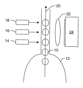
Fig. 2 illustrates one embodiment of an LED based measurement system. As shown
in Fig. 2, microspheres
may be delivered into cuvette 12 by a fluid pump (not shown). The cuvette
provides a detection window through
which measurement of the microspheres may be performed. In one example, the
cuvette may be a standard quartz
cuvette such as that used in standard flow cytometers. Any other suitable type
of viewing or delivery chamber,
however, may also be used to deliver the sample for analysis. The fluid pump
may be, for example, a syringe pump.
The fluid pump may draw sample fluid containing the microspheres out of a
sample fluid container (not shown) and
deliver a drop of the sample fluid into the flow of a sheath fluid (not shown)
at approximately the neck down region
of the cuvette. The neck down region of the cuvette is the portion of the
cuvette that resembles the bottom half of an
hour glass.
The microspheres in the sample fluid pass out of the end of the fluid pump and
become ensheathed in the
sheath fluid. The reduced cross-section of the neckdown region relative to
larger portions of the cuvette causes the
sheath fluid to accelerate. As a result, the confluence of the sample fluid
and the sheath fluid form a coaxial, bi-
component stream with the sample fluid forming the inner component of the
stream. The sheath fluid elongates the
sample fluid thereby causing the microspheres contained therein to flow in
substantially single file by the time they
reach the focal region of LEDs 14, 16, and 18. Again, although the system is
shown in Fig. 2 to include 3 LEDs, it
is to be understood that the system may include any other suitable number of
LEDs.
LEDs 14, 16, and 18 are arranged in an array along flow path 20 of the sample.
The array of LEDs is
configured to illuminate the sample as the sample moves along the flow path.
As shown in Fig. 2, the LEDs may be
positioned in a substantially linear arrangement such that the individual LEDs
each illuminate the sample at
approximately the same angle of illumination. As further shown in Fig. 2, the
LEDs may be arranged such that a
microsphere is illuminated by each LED at a different time. Each of the LEDs
may illuminate the microspheres with
light having approximately the same wavelength or the same range of
wavelengths. For example, each of the LEDs
may be configured to illuminate the microspheres with blue light. The
wavelength or range of wavelengths of light
emitted by the LEDs may vary depending upon, for example, the type of sample
that is being measured and/or a
material associated with the sample (e.g., a material bound to the surface of
the sample microspheres). For example,
in a different embodiment, LEDs 14, 16, and 18 may be configured to emit green
light.
In some embodiments, the system may include one or more lenses configured to
direct (e.g., focus) light
from the LEDs onto the microspheres or the flowpath. For example, as shown in
Fig. 3, the one or more lenses may
include single spherical lens 19 configured to direct light from multiple LEDs
onto the microspheres or the
flowpath. In another example, two or more lenses arranged in a single compound
lens may be used to direct light
from multiple LEDs onto the microspheres or flowpath. In a further example, as
shown in Fig. 4 set of cylindrical
lenses 21 may be configured to direct light from multiple LEDs onto the
microspheres or the flowpath. Each
cylindrical lens of the set may be coupled to one of the LEDs. The one or more
lenses may also include any other
suitable lenses) known in the art.
Light scattered by the microspheres or fluorescence emitted by the
microspheres due to excitation by the
illumination may be collected by lens 22, as shown in Figs. 2-4. In the
embodiment shown in Figs. 2-4, light
scattered or emitted by the microspheres due to illumination by each of the
LEDs 14, 16, and 18 is collected by a
single lens. In one embodiment, the single lens is a spherical lens. In some
embodiments, the lens may include only
one lens. Alternatively, the lens may be a compound lens. Although lens 22 is
shown in Figs. 2-4 to be a refractive
optical component, it is to be understood that the lens may be replaced with a
different type of light directing
CA 02534859 2006-02-06
WO 2005/017498 PCT/US2004/024987
component (e.g., reflective, catadioptric, etc.). All other lenses described
herein may be similarly replaced with
other light directing components.
As described above, the LED illumination may be used for measurements of both
fluorescence emitted by
the microspheres and light scattered by the microspheres. In one such
embodiment, the measurements may be made '
simultaneously with different detectors (such as those shown in Fig. 6 and
described further below) arranged at
suitable positions with respect to the LEDs. In another embodiment, multiple
arrays of LEDs may be used to make
different measurements. One such embodiment of multiple arrays of LEDs is
described further herein. In a
different embodiment, a different (e.g., non-LED) light source (not shown) may
be used to provide illumination for
light scattering measurements of the sample. The light source used for
scattering measurements may include any
suitable light source known in the art. In addition, depending on the
scattering properties of the sample (e.g., the
refractive index of the microspheres), it may be advantageous to use a single
light source having a higher energy
density than that of an LED such that the scattered light has sufficient
intensity to produce adequate output signals.
Lens 22 is configured to direct the collected light onto a photosensitive
surface of detector 24. The lens
may, in some embodiments, be configured to focus the light onto the
photosensitive surface of the detector (e.g., as
in an objective lens). In other embodiments, the lens may be configured to
image the light onto the photosensitive
surface of the detector (e.g., as in an imaging lens). In one embodiment, the
detector may be a photo-multiplier
tube, a photodiode, a linear array of photosensitive elements, a two-
dimensional array of photo-sensitive elements
such as a charge-coupled device (CCD) camera or a time delay integration (TDI)
camera, or any other suitable
detector known in the art. Another method would be to couple the light from
the cuvette, or from lens 22, indirectly
to remotely located optical detectors) via one or more fiber optic cables (not
shown).
Output signals of the detector may be processed as described herein. For
example, the system may include
a processor (not shown in Fig. 2) that may be configured as described herein.
In some embodiments, the output
signals may be processed to determine an identity of the microspheres.
Alternatively, the output signals may be
processed to determine information about a reaction taking place on the
surface of the microspheres or information
about one or more materials associated with the microspheres. The system shown
in Figs. 2-4 may be further
configured as described herein.
In some embodiments, the system may include an LED array that includes
individual LEDs positioned in a
two-dimensional array. In such an array, a first portion of the individual
light emitting diodes may be configured to
illuminate the sample at different positions along the flow path at
approximately the same angle of illumination. A
second portion of the individual light emitting diodes may be configured to
illuminate the sample at one of the
different positions along the flow path at different angles of illumination.
For example, as shown in Fig. 4, the two-dimensional array includes LEDs 14,
16, and 18 that are
configured to illuminate the sample at different positions along the flow path
at approximately the same angle of
illumination. In addition, the array includes LEDs 18, 18a, and 18b that are
configured to illuminate the sample at
one of the different positions (or a single position) along the flow path at
different angles of illumination. In other
words, LEDs 18, 18a, and 18b are arranged at different positions along the z-
axis of the system. The system may
also include other LEDs (not shown) that are configured to illuminate the
sample at other of the different positions
along the flow path at different angles of illumination. Although the z-axis
is shown in Fig. 4 to be generally linear,
the location of the LEDs in any x-plane may vary depending on, for example,
the outer dimensions and/or the shape
of the cuvette (e.g., square, rectangular, circular, etc.).
CA 02534859 2006-02-06
WO 2005/017498 PCT/US2004/024987
As shown in Fig. 4, individual LEDs of the two-dimensional array arranged
along the y-axis are each
coupled to one of individual lenses 21 (or one of a micro-array of lenses)
that are configured to focus light to
different positions along the y-axis. In addition, all three light sources
arranged along the z-axis are each coupled to
one or more individual lenses such that the light from the light sources is
directed to a combined single position
along the flow path. The wavelength of each LED along the z-axis may be the
same to provide increased power, or
different for simultaneous illumination by more than one wavelength. It is
noted that although the system shown in
Fig. 4 includes LEDs arranged along the y-axis as well as the z-axis in a two-
dimensional array, the system may
alternatively include LEDs arranged along only the y-axis as shown in Figs. 2
and 3 or LEDs arranged along only
the z-axis.
In a different embodiment shown in Fig. 5, light scattered or emitted by the
microspheres due to
illumination by individual LEDs 14, 16, and 18 may be separately collected by
lenses 26, 28, and 30. In other
words, each of the lenses collects preferably light resulting from
illumination of the sample by only one LED of the
array. In one embodiment, lenses 26, 28, and 30 may be cylindrical lenses.
However, lenses 26, 28, and 30 may
also include any other suitable lenses known in the art. In some embodiments,
lenses 26, 28, and 30 may have
substantially the same characteristics. Alternatively, lenses 26, 28, and 30
may have different characteristics, which
may vary depending upon, for example, characteristics of detector 24. Lenses
26, 28, and 30 may direct (e.g., focus,
image, etc.) the collected light onto a photosensitive surface of detector 24
directly, or indirectly (e.g., via a fiber
optic cable). Therefore, the system may include more than one collecting lens
optically coupled to one detector.
In addition, lenses 26, 28, and 30 may direct the collected light onto
different areas of the photosensitive
surface of detector 24. Furthermore, lenses 26, 28, and 30 may direct the
collected light onto an area that is less
than the entire area of the photosensitive surface of the detector. However,
the lenses preferably focus the collected
light onto an area that is approximately equal to the entire area of the
photosensitive surface of the detector. In this
manner, the pulse length may be extended to approximately its maximum for a
given detector thereby increasing the
S/N ratio as much as possible. The system shown in Fig. 5 may be further
configured as described herein.
In another embodiment shown in Fig. 6, light scattered or emitted by the
microspheres due to illumination
by each of LEDs 14, 16, and 18 may be separately collected by lenses 26, 28,
and 30. Lenses 26, 28, and 30 may be
configured as described above. Light collected by each of the lenses may be
directed (e.g., focused, imaged, etc.)
onto the photosensitive surface of different detectors. For example, light
collected by lens 26 may be directed onto
a photosensitive surface of detector 32 directly or indirectly (e.g., via a
fiber optic cable). Light collected by lens 28
may be directed onto a photosensitive surface of detector 34 directly or
indirectly (e.g., via a different fiber optic
cable), and light collected by lens 30 may be directed onto a photosensitive
surface of detector 36 directly or
indirectly (e.g., via yet another fiber optic cable). The overall
photosensitive area of detectors 32, 34, and 36 may
be less than the photosensitive area of detector 24 shown in Figs. 2-5. As
such, the signals generated by detectors
32, 34, and 36 may include less stray light or background noise. In this
manner, the overall S/N ratio may be
increased by using more than one detector. In addition, the lenses may direct
the collected light onto an area that is
approximately equal to the entire area of the photosensitive surface of the
detectors. In this manner, the pulse length
may be extended to approximately its maximum for a given system configuration
thereby increasing the S/N ratio as
much as possible. The system shown in Fig. 6 may be further configured as
described herein.
CA 02534859 2006-02-06
WO 2005/017498 PCT/US2004/024987
Fig. 7 illustrates yet another embodiment of an LED based measurement system.
In this embodiment, the
system may be configured to illuminate the microspheres with different
wavelengths of light. For example, the
system may include more than one array of LEDs. In one embodiment, the system
may include a first array of
LEDs, which includes LEDs 38, 40, and 42. In addition, the system may include
a second array of LEDs, which
includes LEDs 44, 46, and 48. Although each array is shown to include three
LEDs by way of example, it is to be
understood that the number of LEDs in each array may vary depending on, for
example, the intensity of the LEDs or
the characteristics of the sample. In addition, although the system is shown
to include two arrays of LEDs, it is to be
understood that the system may include more than two arrays of LEDs.
The first array of LEDs is configured to illuminate the microspheres with a
first wavelength or a first
plurality of wavelengths of light. The second array of LEDs is configured to
illuminate the microspheres with a
second wavelength or a second plurality of wavelengths of light. The second
wavelengths) are different than the
first wavelength(s). For example, the second wavelengths) may include blue
light, and the first wavelengths) may
include green light. In this manner, the microspheres may be illuminated with
different wavelengths of light in one
measurement process. The microspheres may emit different types of fluorescence
depending on the wavelength of
light that is used to excite the microspheres. Therefore, the measurement
system may be capable of making multiple
measurements in a single measurement process. As such, the measurement
capability and sensitivity of the system
may be increased as the number of arrays of LEDs are increased.
The system shown in Fig. 7 may also be configured such that light scattered or
emitted by the microspheres
due to illumination by each of LEDs 38, 40, 42, 44, 46, and 48 may be
separately collected by lenses 50, 52, 54, 56,
58, and 60. In one embodiment, lenses 50, 52, 54, 56, 58, and 60 may be
cylindrical lenses. However, these lenses
may also include any other suitable lenses known in the art. Lenses 50, 52,
54, 56, 58, and 60 may direct (e.g.,
focus, image, etc.) the collected light onto the photosensitive surfaces of
detectors 62, 64, 66, 68, 70, and 72 directly
or indirectly (e.g., via a fiber optic cable). In this manner, each lens may
be optically coupled to a different detector.
In an alternative embodiment, each lens may focus the collected light onto a
photosensitive surface of one detector
(not shown). The different detectors or the single detector may be configured
as described above. In another
embodiment, lenses 50, 52, 54, 56, 58, and 60 may be replaced by a single
lens, which may be configured as
described above. The single lens may be configured to focus the collected
light onto a single detector or a plurality
of detectors directly or indirectly (e.g., via a fiber optic cable). In a
different embodiment, lenses 50, 52, and 54
may be replaced with one lens, and lenses 56, 58, and 60 may be replaced with
another lens. In this manner, each
array of LEDs may include its own collector lens.
Although the arrays of LEDs shown in Fig. 7 are arranged relatively close
together to create an
approximately continuous illumination or detection window, it is to be
understood that the arrays of the LEDs may
be spaced apart along the flow path. In addition, the two arrays of LEDs may
be configured to illuminate the
microspheres at approximately the same direction (e.g., approximately the same
angle of illumination) as shown in
Fig. 7. Alternatively, the two arrays of LEDs may be configured to illuminate
the microspheres at different
directions (e.g., different angles of illumination). In this manner, the
arrays of the LEDs may be spaced from each
other around a perimeter of the cuvette. In this example, the arrays of the
LEDs also may or may not be spaced from
each other along the flow path. For example, the arrays of the LEDs may be
configured to illuminate the
microspheres from different directions at the same time during flow.
Alternatively, the subsets of the LEDs may
11
CA 02534859 2006-02-06
WO 2005/017498 PCT/US2004/024987
illuminate the microspheres from different directions at different times
during flow. The system shown in Fig. 7
may be further configured as described herein.
Fig. 8 illustrates an embodiment of an LED based measurement system along a
plane through the cross-
section of cuvette 12 through which microspheres 10 flow. Therefore, only one
LED 74 of an array of LEDs is
shown in Fig. 8. In addition, it is to be understood that the detection
systems illustrated in Fig. 8 may include one or
more detectors as described above. Furthermore, it is to be understood that
one or more lenses (not shown) may be
optically coupled to each of the detection systems as described above. In a
similar manner, it is to be understood
that one or more lenses (not shown) may be optically coupled to each of the
LEDs in the array as described above.
LED 74 and the array of which it is a part of may also be configured as
described above.
Light scattered forwardly from microspheres 10 may be directed to detection
system 76 by folding mirror
78 or any other suitable light directing component. Alternatively, detection
system 76 may be placed directly in the
path of the forwardly scattered light. In this manner, the folding mirror or
other light directing components may not
be included in the system. In one embodiment, the forwardly scattered light
may be light scattered by the
microspheres at an angle of about 180 degrees from the direction of
illumination by LED 74, as shown in Fig. 8.
The angle of the forwardly scattered light may not be exactly 180 degrees from
the direction of illumination by the
LED such that incident light from the LED may not impinge upon the
photosensitive area of the detection system.
For example, the forwardly scattered light may be light scattered by the
microspheres at angles less than or greater
than 180 degrees from the direction of illumination (e.g., light scattered at
an angle of about 170 degrees, about 175
degrees, about 185 degrees, or about 190 degrees).
Light scattered by the microspheres at an angle of about 90 degrees from the
direction of illumination by
the LED:may also be collected. In one embodiment, this scattered light may be
separated into more than one beam
of light by one or more beamsplitters. For example, light scattered at an
angle of about 90 degrees to the LED may
be separated into two different beams of light by beamsplitter 82. The two
different beams of light may be separated
again by beamsplitters 84 and 86 to produce four different beams of light.
Beamsplitters 82, 84, and 86 may include
any appropriate beamsplitters known in the art such as dichroic mirrors.
Each of the beams of light may be directed to a different detection system,
which may include one or more
detectors. For example, one of the four beams of light may be directed to
detection system 88. Detection system 88
may be configured to detect light scattered by the microspheres. The other
three beams of light may be directed to
detection systems 90, 92, and 94. Detection systems 90, 92, and 94 may be
configured to detect fluorescence
emitted by the microspheres. Each of the detection systems may be configured
to detect fluorescence of a different
wavelength or a different range of wavelengths. For example, one of the
detection systems may be configured to
detect green fluorescence. Another of the detection systems may be configured
to detect yellow-orange
fluorescence, and the other detection system may be configured to detect red
fluorescence.
In some embodiments, spectral filters 96, 98, and 100 may be coupled to each
of the detection systems.
The spectral filters may be configured to block fluorescence of wavelengths
other than that which the detection
system is configured to detect. Another embodiment (not shown) would be to use
one or more fiber optic cables to
direct the emitted fluorescent light to one or more detectors. In the case
where multiple wavelength LEDs are used
as excitation sources along the flow path of the bead or particle, a single
detector or detection system could be used
for each corresponding emission wavelength by imaging each separate area with
multiple fibers. The measurement
system shown in Fig. 8 may be further configured as described herein.
12
CA 02534859 2006-02-06
WO 2005/017498 PCT/US2004/024987
The detectors' output currents are proportional to the fluorescent light
impinging on them and result in
current pulses. The current pulses may be converted to voltage pulses, low
pass filtered, and then digitized by an
A1D converter. Processor 102 such as a DSP integrates the area under the pulse
to provide a number which
represents the magnitude of the fluorescence. In addition, the processor may
perform additional functions described
herein (e.g., combining individual output signals to produce a single output
signal having a S/N ratio that is greater
than a S/N ratio of the individual output signals). As shown in Fig. 8,
processor 102 may be coupled to detector 88
via transmission medium 104. Processor 102 may also be coupled to detector 88
indirectly via transmission medium
104 and one or more other components (not shown) such as the A/D converter.
The processor may be coupled to
other detectors of the system in a similar manner.
Additional examples of measurement systems in which an array of LEDs can be
used to replace the
excitation sources or light sources currently used in the systems are
illustrated in U.S. Patents Nos. 5,981,180 to
Chandler et al., 6,046,807 to Chandler, 6,139,800 to Chandler, 6,366,354 to
Chandler, 6,411,904 to Chandler,
6,449,562 to Chandler et al., and 6,524,793 to Chandler et al., which are
incorporated by reference as if fully set
forth herein. The measurement systems described herein may also be further
configured as described in these
patents.
The various measurement system embodiments described above may be used to
perform a variety of
measurement methods. In one embodiment, a measurement method includes
illuminating a microsphere at different
positions along a flow path of the microsphere. The method also includes
detecting light resulting from illuminating
the microsphere to produce individual output signals corresponding to the
illumination of the microsphere at the
different positions. In addition, the method includes combining the individual
output signals to produce a single
output signal having a S!N ratio that is greater than a S/N ratio of the
individual output signals. The single output
signal also has a pulse length that is greater than a pulse length of each of
the individual output signals.
In one embodiment, illuminating the microsphere may include illuminating the
microsphere with one or
more arrays of LEDs arranged along the flow path of the microsphere. The one
or more arrays are configured to
illuminate the microsphere as the microsphere moves along the flow path. In
some embodiments, illuminating the
microsphere includes illuminating the microsphere at the different positions
with approximately the same
wavelength or wavelengths of light. In another embodiment, illuminating the
microsphere includes illuminating the
microsphere at the different positions at approximately the same angle of
illumination. In an additional
embodiment, illuminating the microsphere includes illuminating the microsphere
at the different positions with a
series of discrete light pulses.
In some embodiments, illuminating the microsphere may include illuminating the
microsphere at one of the
different positions at multiple angles of illumination with multiple
individual LEDs. In one such embodiment, the
multiple individual LEDs generate light of substantially the same wavelength.
In a different such embodiment, the
multiple individual LEDs generate light of different wavelengths. In this
manner, a microsphere may be illuminated
substantially simultaneously with different wavelengths of light or the same
wavelength of light at different angles of
illumination.
In an embodiment, the different positions may be arranged along a first
portion of the flow path. In such an
embodiment, illuminating the microsphere may include illuminating the
microsphere at the different positions with a
first wavelength of light. The method may further include illuminating the
microsphere at additional positions along
a second portion of the flow path of the microsphere with a second wavelength
of light different than the first
13
CA 02534859 2006-02-06
WO 2005/017498 PCT/US2004/024987
wavelength of light. In a different such embodiment, illuminating the
microsphere may include illuminating the
microsphere at the different positions at a first angle of illumination, and
the method may include illuminating the
microsphere at additional positions along a second portion of the flow path of
the microsphere with a second angle
of illumination different than the first angle of illumination.
In some embodiments, illuminating the microsphere may include illuminating the
microsphere at the
different positions with two or more arrays of LEDs configured to produce
light having different wavelengths. In
another embodiment, illuminating the microsphere may include illuminating the
microsphere at the different
positions with two or more arrays of LEDs arranged at different angles of
illumination. In such embodiments, the
two or more arrays may be configured to illuminate the microsphere with a
different wavelength of light at each of
the different angles of illumination or substantially the same wavelength of
light at each of the different angles of
illumination.
In a further embodiment, detecting the light may include detecting the light
resulting from illumination of
the microsphere with one or more detectors. In additional embodiments, the
method may include collecting the light
resulting from illuminating the microsphere and directing the collected light
directly onto a photosensitive surface of
one or more detectors. The one or more detectors perform detecting the light
as described above. In another
embodiment, the method may include collecting the light resulting from
illumination of the microsphere and
directing the collected light indirectly onto a photosensitive surface of one
or more detectors using one or more fiber
optic cables. In this embodiment, the one or more detectors also perform
detecting the light as described above.
In one embodiment, the light resulting from illumination of the microsphere
may include fluorescence
emitted by the microsphere. In a different embodiment, the light resulting
from illumination of the microsphere may
include light scattered by the microsphere. In yet another embodiment, the
light resulting from illumination of the
microsphere may include fluorescence emitted by the microsphere and light
scattered by the microsphere. Each of
the embodiments of the method may include any other steps described herein.
An additional embodiment relates to a computer-implemented method that may be
performed by various
measurement systems described herein. For example, this method may be
performed by processor 102 shown in
Fig. 8. This method includes combining individual output signals to produce a
single output signal having a S/N
ratio that is greater than a S/N ratio of the individual output signals. The
single output signal also has a pulse length
that is greater than a pulse length of each of the individual output signals.
The individual output signals correspond
to light resulting from illumination of a microsphere at different positions
along a flow path of the microsphere.
In one embodiment, the illumination may include illumination by an array of
LEDs arranged along the flow
path of the microsphere. The array is configured to illuminate the microsphere
as the microsphere moves along the
flow path. In another embodiment, the individual output signals are produced
by one or more detectors.
In an additional embodiment, the illumination includes illumination at the
different positions with
approximately the same wavelength or wavelengths of light. In another
embodiment, the illumination may include
illumination at the different positions at approximately the same angle of
illumination. In a further embodiment, the
illumination may include illumination at the different positions at different
angles of illumination using
approximately the same wavelength of light. In a different embodiment, the
illumination includes illumination at the
different positions at different angles of illumination using different
wavelengths of light. In yet another
embodiment, the illumination includes a series of discrete light pulses.
14
CA 02534859 2006-02-06
WO 2005/017498 PCT/US2004/024987
In one embodiment, the light resulting from the illumination includes
fluorescence emitted by the
microsphere. In another embodiment, the light resulting from the illumination
includes light scattered by the
microsphere. In a different embodiment, the light resulting from the
illumination includes fluorescence emitted by
the microsphere and light scattered by the microsphere. Each of the
embodiments of the computer-implemented
signal integration method described above may include any other steps
described herein.
Program instructions implementing methods such as those described herein may
be transmitted over or
stored on the carrier medium. The carrier medium may be a transmission medium
such as a wire, cable, or wireless
transmission link, or a signal traveling along such a wire, cable, or link.
The carrier medium may also be a storage
medium such as a read-only memory, a random access memory, a magnetic or
optical disk, or a magnetic tape.
In an embodiment, a processor may be configured to execute the program
instructions to perform a
computer-implemented method according to the above embodiments. The processor
may take various forms,
including a dedicated processing board employing digital signal processing
chips or field programmable gate arrays,
a personal computer system, mainframe computer system, workstation, network
appliance, Internet appliance,
personal digital assistant ("PDA"), television system or other device. In
general, the term "computer system" may
be broadly defined to encompass any device having one or more digital signal
processing elements or other
processing elements.
The program instructions may be implemented in any of various ways, including
procedure-based techniques,
component-based techniques, and/or object-oriented techniques, among others.
For example, the program instructions
may be implemented using ActiveX controls, C++ objects, JavaBeans, Microsoft
Foundation Classes ("MFC"), or other
technologies or methodologies, as desired. In the case of a FPGA
implementation, the use of high level languages such
as VHDL may be employed to design the signal processing circuit embedded
within the device.
It will be appreciated to those skilled in the art having the benefit of this
disclosure that this invention is
believed to provide light emitting diode based measurement systems. Further
modifications and alternative
embodiments of various aspects of the invention will be apparent to those
skilled in the art in view of this
description. Accordingly, this description is to be construed as illustrative
only and is for the purpose of teaching
those skilled in the art the general manner of carrying out the invention.
It is to be understood that the forms of the invention shown and described
herein are to be taken as the
presently preferred embodiments. Elements and materials may be substituted for
those illustrated and described
herein, parts and processes may be reversed, and certain features of the
invention may be utilized independently, all
as would be apparent to one skilled in the art after having the benefit of
this description of the invention. Changes
may be made in the elements described herein without departing from the spirit
and scope of the invention as
described in the following claims.