Language selection

Search

Patent 2535141 Summary

Third-party information liability

Some of the information on this Web page has been provided by external sources. The Government of Canada is not responsible for the accuracy, reliability or currency of the information supplied by external sources. Users wishing to rely upon this information should consult directly with the source of the information. Content provided by external sources is not subject to official languages, privacy and accessibility requirements.

Claims and Abstract availability

Any discrepancies in the text and image of the Claims and Abstract are due to differing posting times. Text of the Claims and Abstract are posted:

  • At the time the application is open to public inspection;
  • At the time of issue of the patent (grant).
(12) Patent Application: (11) CA 2535141
(54) English Title: ROCK DRILL WATER SEPARATOR
(54) French Title: SEPARATEUR D'EAU DE PERFORATRICE DE ROCHES
Status: Dead
Bibliographic Data
(51) International Patent Classification (IPC):
  • E21B 10/08 (2006.01)
(72) Inventors :
  • BRODIE, JOHN (Australia)
  • EVANS, GRAEME (Australia)
  • JUON, NICHOLAS (Australia)
(73) Owners :
  • BRODIE, JOHN (Australia)
  • EVANS, GRAEME (Australia)
  • JUON, NICHOLAS (Australia)
(71) Applicants :
  • BRODIE, JOHN (Australia)
  • EVANS, GRAEME (Australia)
  • JUON, NICHOLAS (Australia)
(74) Agent: GELSING, SANDER R.
(74) Associate agent:
(45) Issued:
(22) Filed Date: 2006-02-02
(41) Open to Public Inspection: 2007-08-02
Availability of licence: N/A
(25) Language of filing: English

Patent Cooperation Treaty (PCT): No

(30) Application Priority Data: None

Abstracts

English Abstract


A dewatering module adapted to be inserted between a rock drill bit and a
drill string
comprising an outer housing and having a first end remote from the drill bit
and a
second end adapted to lie immediately adjacent the drill bit; an air/water
inlet at the
first end of the module adapted to receive a high pressure composite air and
water
flow from within the drill string and to deliver said flow into a main chamber
within
the module; an inner tubular housing within the chamber defining a passage
within
the chamber from its first and inlet end adjacent the air/water inlet to its
outlet and
second end at the drill bit; the first and inlet end of the inner housing
being shielded
by a first baffle from the composite air water flow entering the chamber; the
first
baffle comprising a deflector overlying the first and inlet end of the inner
housing and
having a skirt being of larger diameter than the tubular inner housing inlet
such that
air entering the inner housing is forced to reverse direction and traverse an
"S" shaped
path to enter the inner housing before traveling therethrough to the drill
bit; a second
laterally extending separator baffle beneath the skirt of the first baffle
located such
that and being of a diameter adequate to prevent direct entry into the inlet
of an
air/water stream deflected from the base of the main chamber upwardly towards
the
inlet of the inner housing; holes in the sides of the outer housing remote
from the
air/water inlet and baffle and adjacent its second end to facilitate
evacuation of water
from the chamber and into the area where debris from the drilling operation is
being
exhausted.


Claims

Note: Claims are shown in the official language in which they were submitted.


6

THE EMBODIMENTS OF THE INVENTION IN WHICH AN EXCLUSIVE PROPERTY OR
PRIVILEGE IS BEING CLAIMED ARE DEFINED AS FOLLOWS:


1 A dewatering module adapted to be inserted between a rock drill bit and a
drill
string comprising an outer housing and having a first end remote from the
drill bit
and a second end adapted to lie immediately adjacent the drill bit; an
air/water
inlet at the first end of the module adapted to receive a high pressure
composite air
and water flow from within the drill string and to deliver said flow into a
main
chamber within the module; an inner tubular housing within the chamber
defining
a passage within the chamber from its first and inlet end adjacent the
air/water
inlet to its outlet and second end at the drill bit; the first and inlet end
of the inner
housing being shielded by a first baffle from the composite air water flow
entering
the chamber; the first baffle comprising a cap like deflector overlying the
first and
inlet end of the inner housing, having a depending skirt overlapping the upper

extremity thereof and being of larger diameter than the tubular inner housing
inlet
such that air entering the inner housing is forced to reverse direction and
traverse
an "S" shaped path to enter the inner housing before traveling therethrough to
the
drill bit; a second laterally extending separator baffle beneath the skirt of
the first
baffle located such that and being of a diameter adequate to prevent entry
into the
inlet of the inner tubular housing of the majority of water in any air/water
stream
deflected from the base of the main chamber upwardly towards the inlet of the
inner housing; holes in the sides of the outer housing remote from the
air/water
inlet and baffle and adjacent its second end to facilitate evacuation of water
from
the chamber and into the area where debris from the drilling operation is
being
exhausted.


2 A dewatering module in accordance with claim 1 wherein the first baffle is
formed as a conical hat with an annular skirt portion depending from the lower

portions thereof.


3 A dewatering module in accordance with claim 1 wherein the second baffle is
formed as an downwardly facing frustro-conical extension laterally extending


7


from the inner tubular housing at a position below of the skirt of the first
baffle
but proximate thereto and of a diameter equal to or greater than that of the
skirt of
the first baffle; the purpose of which second baffle is to help prevent water
and
water spray from entering the inlet of the tubular housing.


4 A dewatering module in accordance with claim 1 wherein the inlet to the
tubular
inner housing is formed as a lateral extension from the inner tubular housing
and
extending from a position below the skirt of the first baffle; the purpose of
which
supplementary baffle is to help prevent water and water spray from entering
the
inlet of the tubular housing.


A dewatering module in accordance with claim 1 wherein the inlet of the inner
tubular housing is formed into a supplementary baffle by reason of its shaping
as
an upwardly facing frustro-conical lateral extension to the tube being of
greater
diameter than the tube and lesser diameter than the inside of the skirt of the
first
baffle the purpose of which supplementary baffle is to help prevent reflected
water
and water spray from entering the inlet of the tubular housing.


6 A dewatering module in accordance with claim 1 including a removable grating

adapted to filter solid particles from the air/water flow into the module.


7 A dewatering module as hereinbefore described with reference to one or more
of
the accompanying drawings.


Description

Note: Descriptions are shown in the official language in which they were submitted.


CA 02535141 2006-02-02
1

ROCK DRILL WATER SEPARATOR
Field of the Invention
The present invention relates to rock drill dust suppression apparatus and in
particular
to a unit adapted to sit behind the drill bit and separate water from the
composite air
and water stream commonly directed through rock drill strings towards drill
bits.

1 o Background of the Invention
Typically rock drills such as are utilised to create bores in which to place
explosive
charges comprise a drill bit mounted at the forward end of a drill string
which string
consists of sections joined together by appropriate connectors. In order to
assist in
evacuation of debris created by the action of the drill bit on the rock air is
delivered at
high pressure through a bore of the drill string to the drill bit. This air
then exhausts
with debris back up the hole being created by the drill between the drill
string and the
sides of the hole being drilled.

Typically this evacuation of debris laden air creates enormous volumes of dust
which
adversely effect the environment, workers and mechanical equipment.
Consequently
it has been found to be desirable to inject water into the air and debris
exhausting
from the cutting face. It is practical to deliver the water and air together
down the
centre of the drill string to the area adjacent the drill bit. Whereas it is
important that
the air reaches the cutting face at the front of the drill bit is undesirable
that water be
delivered to the front of the drill bit as this produces a slurry which causes
wear on the
cutting services of the drill bit and furthermore creates corrosion
difficulties for the
bearings and components in and adjacent the drill bit.

Typically therefore apparatus exists, such as that described in US Patent
5927439, for
separating the water and air flow in an assembly just behind the drill bit to
facilitate
delivery of the air to the drill bit and evacuation of the water from the
interior of the


CA 02535141 2006-02-02
2

drill string to the exterior of the drill string just before it reaches the
vicinity of the
drill bit.

Object of the Invention
Existing dewatering modules which are installed at the end of the drill string
and
behind the drill bit are complex, expensive and to some extent inefficient and
it is
consequently an object of the present invention to ameliorate one more of the
above-
mentioned disadvantages with existing dewatering units or at least to provide
the
market with an alternative.


Short Summary of the Invention
According to the present invention there is disclosed a dewatering module
adapted to
be inserted between a rock drill bit and a drill string comprising an outer
housing and
having a first end remote from the drill bit and a second end adapted to lie
immediately adjacent the drill bit; an air/water inlet at the first end of the
module
adapted to receive a high pressure composite air and water flow from within
the drill
string and to deliver said flow into a main chamber within the module; an
inner
tubular housing within the chamber defining a passage within the chamber from
its
first and inlet end adjacent the air/water inlet to its outlet and second end
at the drill
bit; the first and inlet end of the inner housing being shielded by a first
baffle from the
composite air water flow entering the chamber; the first baffle comprising a
deflector
overlying the first and inlet end of the inner housing and having a skirt
being of larger
diameter than the tubular inner housing inlet such that air entering the inner
housing is
forced to reverse direction and traverse an "S" shaped path to enter the inner
housing
before traveling therethrough to the drill bit; a second laterally extending
separator
baffle beneath the skirt of the first baffle located such that and being of a
diameter
adequate to prevent direct entry into the inlet of an air/water stream
deflected from the
base of the main chamber upwardly towards the inlet of the inner housing;
holes in
the sides of the outer housing remote from the air/water inlet and baffle and
adjacent
its second end to facilitate evacuation of water from the chamber and into the
area
where debris from the drilling operation is being exhausted.


CA 02535141 2006-02-02
3
Brief Description of the Drawinjzs

One embodiment of the present invention will now be described with reference
to the
accompanying drawings in which:

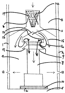
Figure 1 is a longitudinal sectional view through a dewatering module in
accordance
with the present invention and
Figure 2 is a second longitudinal sectional view through a dewatering module
in
accordance with the present invention.

Preferred Mode of Carrying out the Invention
According to the embodiment of Figure 1 there is disclosed a dewatering module
1
comprising an outer tubular housing 2 and an air/ water inlet 3 adjacent first
end 4
thereof. The second end 5 of the module is adapted to receive a drill bit (not
shown) in
a standard mount 6.
The module 1 defines a chamber 7 which in turn contains an inner tubular
housing 8
extending from a first inlet end 2 to a second outlet end 10 adjacent the
drill bit (not
shown). The inlet end 9 of inner tubular housing 8 is covered by baffle 11
comprising
conical hat portion 12 and depending skirt portion 13. It will be observed
that the
diameter of depending skirt 13 is greater than that of the inlet 9 to inner
tubular
housing 8 hence allowing passage of air between the skirt and the outer and
upper
extremities of tubular housing 8.

In use the module operates by receiving a pressurised air/water flow through
inlet 3 in
the direction indicated by arrow 14. This flow is directed onto the centre of
conical
baffle 11. The inertia of the water contained within the flown causes the
water to
continue down a path indicated by arrow 15 which direction is deflected and
modified
by the baffle but is not the same as the path of the majority of air in the
flow which air


CA 02535141 2006-02-02
4

traverses a path indicated by arrows 16. The lighter air is able to traverse
the "S"
shaped path necessary for the air to enter into tubular housing 8. Since the
tubular
housing 8 has a large outlet 10 adjacent the drill bit (not shown) it remains
at lower
pressure than the inlet air. Separation of air and water flow is therefore
achieved.
Water then exits the module via holes 17 in the outer housing 2 due to the
centrifugal
force of the rotating module forcing the relatively heavy water to the outside
of
chamber 7.

The inlet 9 of the inner tubular housing is formed into a supplementary baffle
by
reason of it being shaped as an upwardly facing frustro-conical extension to
tubular
housing 8. The inlet 9 is hence of greater diameter than the tube and lesser
diameter
than the inside of the skirt 13 of the first baffle 12. The purpose of the
inlet 9 being
formed as a supplementary baffle is to help prevent reflected water and water
spray
from entering the inlet of the tubular housing 8.


It will be noted that this embodiment additionally includes second baffle 18
the
purpose of which is to help prevent water and water spray from entering
tubular
housing 8. The second baffle is formed as an downwardly facing frustro-conical
extension laterally extending from the inner tubular housing at a position
below the
skirt of the first baffle and of a diameter equal to or greater than that of
the skirt of the
first baffle; the purpose of which second baffle is to help prevent water and
water
spray from entering the inlet of the tubular housing. To achieve this purpose
it must
be located fairly close to the lower extremity of the skirt of the first
baffle.

Ideally a grating 19, removable so as to facilitate cleaning, may be
incorporated in
inlet 3. The grating serves the purpose of filtering and ensuring that the
water entering
the module contains no large particles which may clog the module hence
rendering it
inefficient or inoperative. Ideally the grating should catch particles of a
size greater
than 0.5 mm in diameter or of a size equal to or greater than holes 17. It
will be
appreciated that alternative embodiments of the present invention may be
devised


CA 02535141 2006-02-02

apart from that example described above without departing from the scope and
internment of the present invention.

Representative Drawing
A single figure which represents the drawing illustrating the invention.
Administrative Status

For a clearer understanding of the status of the application/patent presented on this page, the site Disclaimer , as well as the definitions for Patent , Administrative Status , Maintenance Fee  and Payment History  should be consulted.

Administrative Status

Title Date
Forecasted Issue Date Unavailable
(22) Filed 2006-02-02
(41) Open to Public Inspection 2007-08-02
Dead Application 2010-02-02

Abandonment History

Abandonment Date Reason Reinstatement Date
2009-02-02 FAILURE TO PAY APPLICATION MAINTENANCE FEE

Payment History

Fee Type Anniversary Year Due Date Amount Paid Paid Date
Application Fee $200.00 2006-02-02
Maintenance Fee - Application - New Act 2 2008-02-04 $50.00 2007-10-31
Owners on Record

Note: Records showing the ownership history in alphabetical order.

Current Owners on Record
BRODIE, JOHN
EVANS, GRAEME
JUON, NICHOLAS
Past Owners on Record
None
Past Owners that do not appear in the "Owners on Record" listing will appear in other documentation within the application.
Documents

To view selected files, please enter reCAPTCHA code :


To view images, click a link in the Document Description column. To download the documents, select one or more checkboxes in the first column and then click the "Download Selected in PDF format (Zip Archive)" or the "Download Selected as Single PDF" button.

List of published and non-published patent-specific documents on the CPD .

If you have any difficulty accessing content, you can call the Client Service Centre at 1-866-997-1936 or send them an e-mail at CIPO Client Service Centre.


Document
Description 
Date
(yyyy-mm-dd) 
Number of pages   Size of Image (KB) 
Abstract 2006-02-02 1 36
Description 2006-02-02 5 175
Claims 2006-02-02 2 79
Drawings 2006-02-02 2 54
Representative Drawing 2007-07-05 1 11
Cover Page 2007-07-27 2 58
Drawings 2007-10-31 2 48
Correspondence 2006-03-02 1 18
Assignment 2006-02-02 3 90
Correspondence 2007-05-02 3 100
Fees 2007-10-31 2 68
Correspondence 2007-10-31 1 20