Note: Descriptions are shown in the official language in which they were submitted.
CA 02535236 2006-02-03
PA-US 20040134
SPECIFICATION
TTTT.F
"MECHANISM FOR DISPENSING SHAVED ICE FROM A REFRIGERATION
APPLIANCE"
BACKGROUND OF THE INVENTION
[0001] Appliances are known for dispensing ice in multiple forms, such as ice
cubes
and crushed ice. Some appliances that dispense ice in that fashion are
domestic refrigeration
appliances such as combined refrigerator/freezer appliances where the ice
cubes and crushed
ice are delivered through the door of the appliance, such as shown and
described in U.S.
Patent Nos. 4,176,527, 5,050,777, 6,050,097 and 6,082,130. Other devices are
known for
dispensing shaved ice, however, these are typically stand alone appliances
that dispense only
shaved ice, such as those disclosed in U.S. Patent Nos. 4,718,610, 4,745,773
and 5,513,810.
[0002] Many shaved ice dispensers require time to set up, clean and stow, and
also
require adult supervision, preventing them from being used independently by
children.
[0003] U.S. Patent No. 5,680,771 discloses a mechanism for producing only
shaved
ice in a refrigeration appliance in which a dedicated ice container is used
for the freezing of a
discrete quantity of water, and which is manipulated and driven relative to a
fixed blade for
producing a quantity of shaved ice. Operation of the mechanism requires the
manual
manipulation of two separate pivotable or rotatable handles, which can only be
accessed
through the opening of a door of the freezer compartment of the refrigeration
appliance.
[0004] It would be an improvement in the art if there were provided a
mechanism for
dispensing ice in multiple forms, including each of ice cubes, crushed ice and
shaved ice. It
would also be an improvement in the art if a refrigeration appliance were
provided that
dispensed each of ice cubes, crushed ice and shaved ice. It would further be
an improvement
in the art if a refrigeration appliance were provided that dispensed shaved
ice through the
door of the appliance.
SUMMARY OF THE INVENTION
[0005) The present invention provides a mechanism for dispensing shaved ice
from a
refrigeration appliance. In an embodiment of the invention, the shaved ice is
dispensed
through a door of the refrigeration appliance. In an embodiment of the
invention, the
CA 02535236 2006-02-03
PA-US 20040134
refrigeration appliance includes a refrigerated compartment, an ice making
mechanism in the
refrigerated compartment, an ice delivery system arranged to deliver ice from
the ice making
mechanism, an ice shaving mechanism located in the refrigeration appliance
arranged to
selectively shave ice received from the ice delivery system, and an ice
dispensing system
arranged to dispense ice, wherein ice may be dispensed in a shaved condition
or a non-shaved
condition.
[0006] In an embodiment, the refrigeration appliance may include a reservoir
arranged
to hold a supply of ice cubes, a dispensing zone, a delivery mechanism
arranged for
dispensing ice cubes from the reservoir to the dispensing zone, an ice shaving
mechanism
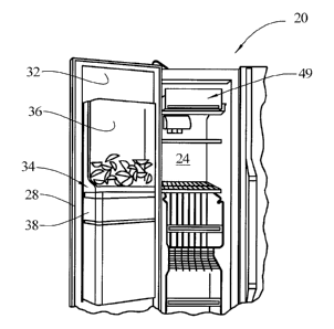
located in the dispensing zone arranged to selectively shave ice, and a
control mechanism
arranged to selectively activate the ice shaving mechanism upon receipt of an
appropriate
input from a user.
[0007] In an embodiment, a mechanism is provided for dispensing ice in
multiple
forms, including each of ice cubes, crushed ice and shaved ice.
[0008] In an embodiment, the mechanism may include a reservoir arranged to
hold a
supply of ice cubes, a dispensing zone, a delivery mechanism arranged for
dispensing ice
cubes from the reservoir to the dispensing zone, an ice crushing mechanism
located in the
dispensing zone arranged to selectively crush ice, an ice shaving mechanism
located in the
dispensing zone arranged to selectively shave ice, and a control mechanism
arranged to
selectively activate the ice crushing mechanism and the ice shaving mechanism
upon receipt
of an appropriate input from a user.
[0009] In an embodiment, the mechanism is provided within a refrigeration
appliance
and the ice forms, including shaved ice, are dispensed through a door of the
appliance. Such
an arrangement confines the moving parts of the mechanism within the appliance
or the door
of the appliance such that the mechanism is safe to use, and such that
children can use the
mechanism without adult supervision. Also, the mechanism does not require
separate set up
or clean up operations, but is always ready for use.
[0010] In an embodiment, the ice crushing mechanism comprises an arm rotatably
driven by a motor.
-2-
CA 02535236 2006-02-03
PA-US 20040134
[0011] In an embodiment, the ice shaving mechanism comprises a pusher
rotatably
driven by a motor for pushing ice and a fixed blade against which the ice is
pushed by the
rotating pusher.
[0012] In an embodiment, the ice shaving mechanism comprises a pusher and a
blade,
at least one of which is rotated relative to the other by a motor.
[0013] In an embodiment, the dispensing outlet comprises a vertical passage.
[0014] In an embodiment, the dispensing outlet comprises a non-vertical
passage.
[0015] In an embodiment, the dispensing outlet comprises a movable door to
collect a
batch of shaved ice prior to dispensing.
[0016] In an embodiment, the dispensing outlet comprises an auger to collect a
batch
of shaved ice prior to dispensing.
[0017] In an embodiment, the dispensing outlet comprises a paddle to collect a
batch
of shaved ice prior to dispensing.
[0018] In an embodiment, the dispensing zone comprises a single well in which
each
of ice cubes, crushed ice and shaved ice is dispensed to a user.
[0019] In an embodiment, a movable door is provided to allow ice to bypass
said ice
shaving mechanism.
[0020] In an embodiment, the single well includes a pusher and a plate having
different openings therein for selective passage of ice cubes, crushed ice and
shaved ice.
[0021] In an embodiment, a cover is positioned over the plate, the cover
having an ice
passage therethrough, and being rotatable relative to the plate.
[0022] In an embodiment, the dispensing zone comprises two wells, wherein
through
a first well, two of the three ice forms are dispensed to a user and through a
second well, a
third of the three ice forms is dispensed to a user.
[0023] In an embodiment, the ice crushing mechanism comprises an arm rotatably
driven by a motor and the ice shaving mechanism comprises a pusher rotatably
driven by a
motor for pushing ice and a fixed blade against which the ice is pushed by the
rotating pusher,
wherein the motor driving the arm of the ice crushing mechanism and the motor
driving the
pusher of the ice shaving mechanism comprise the same motor.
BRIEF DESCRIPTION OF THE DRAWING
-3-
CA 02535236 2006-02-03
PA-US 20040134
[0024] FIG. 1 is a front view of a refrigerator apparatus having a mechanism
for
delivering ice embodying the present invention.
[0025] FIG. 2 is a fragmentary perspective view illustrating the mechanism
within the
freezer compartment of the refrigerator apparatus with the freezer door open.
[0026] FIG. 3 is a schematic illustration of the mechanism components in a
single
well configuration.
[0027] FIG. 4 is a schematic illustration of the mechanism components in a two
well
configuration.
[0028] FIG. 5 is a perspective view illustrating the mechanism in a single
well
configuration.
[0029] FIG. 6 is side cross sectional schematic illustration of an embodiment
of the
mechanism components in the single well configuration.
[0030] FIG. 7 is a top perspective view of the embodiment illustrated in FIG.
6.
[0031] FIG. 8 is a partial top perspective view of an embodiment of the
mechanism in
a single well configuration.
[0032] FIG. 9 is a partial top perspective view of an embodiment of the
mechanism in
a single well configuration.
[0033] FIG. 10 is a top view illustrating the ice pusher component in
isolation.
[0034] FIG. 11 is a top perspective view illustrating the ice pusher component
in
isolation.
[0035] FIG. 12 is a top view of an embodiment of the ice pusher component in
isolation.
[0036] FIG. 13 is a bottom view of an embodiment of the ice pusher component
in
isolation.
[0037] FIG. 14 is a side perspective view of an embodiment of the ice pusher
component in isolation.
[0038] FIG. 15 is side perspective view of an embodiment of the ice pusher
engaging
the delivery dispensing zone.
[0039] FIG. 16 is a side perspective view of an embodiment of the ice pusher
and
shaving plate in the dispensing zone.
-4-
CA 02535236 2006-02-03
PA-US 20040134
[0040] FIG. 17 is a cross sectional schematic illustration of an embodiment of
the
mechanism components in the single well configuration.
[0041] FIG. 18 is a top perspective view illustrating an embodiment of the ice
form
selection plate of the single well configuration.
[0042] FIG. 19 is a top perspective view illustrating another embodiment of
the ice
form selection plate of the single well configuration.
[0043] FIG. 20 is a top perspective view illustrating another embodiment of
the ice
form selection plate of the single well configuration.
[0044] FIG. 21 is a side perspective view illustrating a cylindrical ice
shaving
member.
[0045] FIG. 22 is a top view illustrating a rectangular ice shaving member.
[0046] FIG. 23 is a top view illustrating a circular ice shaving member.
[0047] FIG. 24 is a top perspective view illustrating a portion of the ice
shaving
mechanism with a cylindrical ice shaving member on a horizontal axis.
[0048] FIG. 25 is a top perspective view illustrating a portion of the ice
shaving
mechanism with a cylindrical ice shaving member on a vertical axis.
[0049] FIG. 26 is a side perspective view illustrating a cylindrical ice
shaving member
with a cam surface.
[0050] FIG. 27 is a top perspective view illustrating a circular ice shaving
member
with a cam surface.
[0051] FIG. 28 is a top perspective view illustrating a rectangular ice
shaving member
with a cam surface.
[0052] FIG. 29 is a top perspective view illustrating a portion of the ice
shaving
mechanism with a cylindrical ice shaving member on a horizontal axis.
[0053] FIG. 30 is a top perspective illustration of an embodiment of the
mechanism
components in the single well configuration.
[0054] FIG. 31 is a side perspective view illustrating a cylindrical ice
shaving member
with an interior driving axle.
[0055] FIG. 32 is a side perspective view illustrating a cylindrical ice
shaving member
with an exterior driving axle.
-5-
CA 02535236 2006-02-03
PA-US 20040134
[0056] FIG. 33 is a top perspective view illustrating a rectangular ice
shaving member
with a rotating cam.
[0057] FIG. 34 is a top perspective view illustrating a circular ice shaving
member
with a central or an outer drive mechanism.
[0058] FIG. 35 is a side perspective view of an embodiment of the ice pusher
and
shaving plate in the dispensing zone.
[0059] FIG. 36 is a top perspective view of the adjustable height shaving
blade used
in the embodiment of FIG. 35.
[0060] FIG. 37 is a side perspective view of an embodiment of the ice pusher
and
shaving blade in the dispensing zone.
[0061] FIG. 38 is a side perspective view of an embodiment of the ice pusher
and
shaving blade in the dispensing zone.
[0062] FIG. 39 is a top perspective view illustrating a portion of the ice
shaving
mechanism.
[0063] FIG. 40 is a top perspective view illustration of the mechanism in a
two well
configuration.
[0064] FIG. 41 is a top perspective exploded illustration of the mechanism of
FIG. 40.
[0065] FIG. 42 is a side cross sectional schematic illustration of the ice
crushing
mechanism components in the two well configuration.
[0066] FIG. 43 is a top perspective view illustration of the mechanism in a
two well
configuration.
[0067] FIG. 44 is a top perspective view illustrating a portion of the ice
crushing
mechanism for use in the configuration of FIG. 43.
[0068] FIG. 45 is a top perspective exploded illustration of the ice shaving
mechanism
for use in the configuration of FIG. 43.
[0069] FIG. 46 is a side cross sectional schematic illustration of an
embodiment of the
shaved ice delivery mechanism components.
[0070] FIG. 47 is a side cross sectional schematic illustration of an
embodiment of the
shaved ice delivery mechanism components.
[0071] FIG. 48 is a side cross sectional schematic illustration of an
embodiment of the
shaved ice delivery mechanism components.
-6-
CA 02535236 2006-02-03
PA-US 20040134
DETAILED DESCRIPTION OF THE PREFERRED EMBODIMENT
[0072] The present invention provides a mechanism for delivering ice in each
of three
selected forms, namely, cubed, crushed and shaved. This mechanism can be
arranged within
an appliance such as a domestic refrigerator having a refrigerated
compartment, or other types
of appliances, including freezers and ice makers.
[0072] The present invention further provides for dispensing shaved ice from a
refrigeration appliance. The shaved ice may be dispensed through a door of the
appliance.
The refrigeration appliance may have a refrigerated compartment, held below
room
temperature, and perhaps, but not necessarily, below freezing temperature, an
ice making
mechanism in the refrigerated compartment, an ice delivery system arranged to
deliver ice
from the ice making mechanism, an ice shaving mechanism located in the
refrigeration
appliance arranged to selectively shave ice received from the ice delivery
system, and an ice
dispensing system arranged to dispense ice, wherein ice may be dispensed in a
shaved
condition or a non-shaved condition, as described in greater detail below.
[0073] In order to describe a preferred embodiment of the invention, the
environment
of a side-by-side refrigerator is illustrated and discussed, however, it
should be understood
that the present invention is not limited to use in such an environment.
[0074] Generally, as used herein, ice cubes are bodies of ice having a three
dimensional shape, wherein a length in any of the dimensions is not less than
about 2 cm.
Shaved ice comprises bodies of ice having a three dimensional shape, in which
at least one of
the dimensions has a length of no greater than about 5 mm. Crushed ice
comprises bodies of
ice having a three dimensional shape, in which at least one of the dimensions
has a length
greater than about 5 mm, but less than about 2 cm and no dimension has a
length greater than
about 5 cm.
[0075] In FIG. 1 there is illustrated a side-by-side domestic refrigerator 20
having a
refrigeration compartment 22 and a freezer compartment 24, each accessed by a
respective
door 26, 28. Located in the door 28 of the freezer compartment 24 is
illustrated a dispenser
30 which allows for the dispensing of ice and perhaps water through the
freezer door. It
should be noted that the dispenser 30 could also be located in the
refrigerator door 26, and
that the arrangement of the refrigeration compartment 22 relative to the
freezer compartment
24 could be different, such as by having the freezer compartment located above
or below the
CA 02535236 2006-02-03
PA-US 20040134
refrigeration compartment. See, for example, U.S. Patent No. 5,375,432,
incorporated herein
by reference.
[0076] Located on a back side 32 of the freezer door 28, as shown in FIG. 2
and
schematically in FIGs. 3 and 4, is a mechanism 34 for delivering ice in each
of three selected
forms, namely, cubed, crushed and shaved. The mechanism 34 includes a supply
mechanism
for supplying ice cubes, which may include an ice making mechanism and/or a
reservoir 36
arranged to hold a supply of ice cubes. The mechanism 34 for delivering ice
further includes
a dispensing zone 38, a user interface 39 and a control mechanism 40 arranged
to effect
dispensing ice cubes from the reservoir to the dispensing zone, potentially an
ice crushing
mechanism 42 located in the dispensing zone arranged to selectively crush ice,
an ice shaving
mechanism 44 located in the dispensing zone arranged to selectively shave ice,
the control
mechanism 40 also arranged to selectively activate the ice crushing mechanism
and the ice
shaving mechanism upon receipt of an appropriate input from a user via the
user interface 39
which may include selection switches 47 located in or near the dispenser 30. A
dispensing
outlet 48 may also be provided where the ice in the form of cubes, crushed ice
or shaved ice is
dispensed to the user through the door 28 of the refrigerator 20 at the
dispenser 30. In an
alternate embodiment, the ice, either cubed, crushed or shaved may be
dispensed to a
container located within the refrigeration appliance. The reservoir 36 and the
dispensing zone
38 may be physically assembled as a single unit, removable and attachable to
the refrigeration
appliance 20 in one piece, or they may be constructed as separate units,
joined together when
assembled in the appliance.
[0077] The mechanism 34 for delivering ice may be arranged with a single,
relatively
linear path for the ice, as schematically illustrated in FIG. 3 or it may be
arranged with a dual
path for the ice, as schematically illustrated in FIG. 4.
[0078] In the single path arrangement, as schematically illustrated in FIG. 3,
and also
in FIGs. 5-7 and referred to as a single well configuration, all of the ice
passes along the same
path, regardless of whether it is delivered as ice cubes, crushed ice or
shaved ice.
[0079] Generally, ice, in the form of cubes, which may have been made in an
ice
forming unit 49 associated with the appliance 20 that the mechanism 34 is
located within, is
dispensed from the ice forming unit to an ice storage reservoir 36. Ice may be
transported to
the reservoir 36 from the ice forming unit 49 by gravity or some other known
delivery
_g_
CA 02535236 2006-02-03
PA-US 20040134
mechanism. The ice accumulates in the reservoir 36 until the user makes a
demand for the
ice. Known shut off mechanisms may be provided to terminate the formation of
additional
ice by the ice forming unit 49 when the reservoir has reached its capacity.
The reservoir 36
may have an opening 50 in a bottom side 52 thereof through which the ice
passes into the
dispensing zone 38 as one form of delivery mechanism. Such an arrangement
would allow
for a gravity feed of the ice into the dispensing zone 38. An ice stirring arm
53, or an ice
moving auger (another type of delivery mechanism used, particularly if the ice
is delivered to
the dispensing zone 38 horizontally rather than vertically) may be provided to
assist in
moving the ice cubes from the reservoir 36 to the dispensing zone 38 and to
prevent ice
bridges from forming.
[0080] Positioned within the dispensing zone 38 is the ice crushing mechanism
42
and the ice shaving mechanism 44 (FIGS. 3,6 and 7). The ice crushing mechanism
42 may be
a commonly used arrangement wherein one or more rotating fingers 54 are driven
by a motor
56 to crush ice cubes between the finger and a fixed part 57 of the mechanism,
such as taught
in U.S. Patent Nos. 4,176,527, 5,050,777, 6,050,097 and 6,082,130, the
disclosures of each
being incorporated herein by reference.
[0081] An example of such an arrangement is illustrated in FIGS. 6-9 wherein a
rotating arm 55 is provided with fingers 54 extending radially inside the
dispensing zone 38.
One side 59 of the forgers 54 has serrated teeth, the other side 61 is an
extended, smooth
surface. In the crushing mode, the motor 56 rotates the arm 55 in a first
direction A and the
serrated fingers 54 grab and crush the cubes against a stationary grate 57 in
the dispensing
zone 38. In a shaving mode, the motor 56 turns the arm 55 in the opposite
direction B and the
smooth surface 61 of the fingers 54 push cubes against a cutting blade 60. In
an ice cube
dispensing mode, the motor 56 turns the same direction B as for shaving and
ice exits through
a trap door 66. A sweep finger 54a (FIG. 9) could be provided to push ice
fragments formed
by the crusher fingers 54 through the open trap door 66 for dispensing.
[0082] As shown in FIGS. 6 and 7, the ice shaving mechanism 44 may include an
impeller or ice pusher 58 pushing the ice over the shaving blade 60 or
multiple blades. The
same motor 56 that drives the crushing finger 54 may drive the ice pusher 58,
or if desired, a
separate motor may be used.
-9-
CA 02535236 2006-02-03
PA-US 20040134
[0083] An embodiment of the ice pusher 58 is shown in isolation in FIGs. 10-13
where it is seen that there is at least one passage 62 therethrough for the
ice and a lower side
ramped surface 64 for camming the ice against the shaving blade 60. The ice
pusher 58 may
include one or several helical blades forming the lower side ramped surface
64. Also, the
lower side ramped surface 64 may be specially modified, for example being
provided with
surface features 65 such as bumps, grooves or coatings to grip and hold the
ice cubes against
the shaving blade 60 and to prevent the ice cubes from jamming. The ice pusher
58 may be
removable from the mechanism to permit cleaning and replacement, if necessary.
[0084] As shown in FIG. 14, the dispensing zone 38 may include one or more
protrusions 67 for activating or jostling the ice cubes during the rotation of
the ice pusher 58.
These protrusions 67 may be formed on the side walls of the dispensing zone
38, such as in
the form of fingers which protrude into a slot 71 in the ice pusher 58. Such
protrusions 67
may be separately attached or may be formed integrally with the walls of the
dispensing zone
38. The protrusions 67 may also be provided at or on a surface against which
the ice cubes
are pressed by the ice pusher 58, such as a surface 73 which carries the
shaving blade 60.
Such protrusions 67 may be used to prevent the ice cubes from jamming in the
dispensing
zone 38 and to improve shaving performance.
[0085] In an alternate embodiment, the ice pusher 58 may have a lower,
contoured
surface 75 arranged to ride on a cam surface 77 (FIG. 15) of the dispensing
zone 38 which
results in the ice pusher moving one or more vertical cycles during each
revolution of the ice
pusher. This vertical movement will have the effect of "vibrating" the ice
pusher 58 at a high
frequency to discourage ice cube jamming.
[0086] To have the ice cubes avoid the shaving mechanism 44, and to deliver
only ice
cubes or crushed ice, there may be provided the trap door or bypass door 66
(FIGS. 6, 7 and
9), such as at the surface 73 that carries the shaving blade 60. A solenoid 68
or some other
mechanical or electromechanical device may be used to open the bypass door 66,
as
controlled by the control mechanism 40. Also, the ice shaving mechanism 44 may
be placed
upstream (towards the ice reservoir 36) of the ice crushing mechanism 42 in an
alternate
embodiment. The blade 60 or blades of the ice shaving mechanism 44 may be
turned, while
the ice pusher 58 is held stationary, or both may move. The driving force for
either or both of
-lo-
CA 02535236 2006-02-03
PA-US 20040134
the blades 60 (if movable) and the ice pusher 58 (if movable) may be the motor
56 used for
ice crushing, or a separate motor or motors may be utilized.
[0087] In an alternative embodiment, as shown in FIG. 16, the ice pusher 58
may be
stationary and the surface 73 carrying the shaving blades) 60 may be
rotatable. As the
surface 73 is rotated, the shaving blades) 60 will shave the ice cubes and
will also force the
ice cubes into the ever smaller height between the surface 73 and the ice
pusher lower side
ramp surface 64. In such an arrangement, the ice pusher 58 may be a separate
component, or
may be formed as part of the dispensing zone 38 itself.
[0088] In order to form crushed ice as opposed to shaved ice, the shaving
apparatus
can be modified by increasing the height of the blade above the shaving
surface, increasing
the width of the slot in front of the cutting blade on the surface through
which the ice exits the
dispensing zone, or increasing the angle between the cutting blade and the
surface carrying
the blade. An example of such an arrangement is now described.
[0089] In an embodiment of the single well arrangement schematically
illustrated in
FIG. 17, the ice pusher 58, such as an impeller, may be used along with a
plate 72 that is
rotated to a desired selection to present openings 74, 76, 78 for ice cubes,
crushed ice or
shaved ice, respectively. An embodiment of such a plate 72 is shown in
isolation in FIG. 18.
In such an arrangement, crushed ice is formed by the pusher 58 moving the ice
bodies against
a fixed blade-like raised edge 80 of the opening 76 in the plate 72 which is
relatively larger
than the opening 78 in the plate having a fixed blade-like raised edge 86 for
generating
shaved ice.
[0090] The plate 72 may be rotated to an angular position corresponding to a
desired
selection through the power of a motor 88, solenoid, or similar arrangement
and various
switches 90 or sensors may be used to determine the position of the plate, all
as controlled by
the control mechanism 40 based upon user selection. The plate 72 may
alternatively be held
stationary, and a cover 92 (FIG. 17) with an opening 94 therethrough may be
provided that
may rotate on top of the plate to reveal an appropriate portion of the plate
corresponding to
the desired ice type selection. Again, a motor 88, solenoid, or similar
arrangement may
power the rotation of the cover 92 and various switches 96 or sensors may be
used to
determine the position of the cover.
-11-
CA 02535236 2006-02-03
PA-US 20040134
[0091] Alternative embodiments of the plate 72 are shown in FIGs. 19 and 20.
In
FIG. 19, blades 80, 86 and openings 76, 78 are positioned and arranged to
provide either
crushed ice or shaved ice. In FIG. 20, blades 86 and opening 74 are positioned
and arranged
to provide either cubed ice or shaved ice.
[0092] Alternative embodiments of the ice shaving mechanism are illustrated in
FIGs.
21-23. In FIG. 21, a shaving mechanism utilizes a cylinder for carrying the
shaving blade 60.
The blade 60 can be arranged to extend from an exterior cylindrical surface
202 or from the
interior cylindrical surface 204. As described above, either surface may be
provided with
treatments 206 such as bumps, grooves, protrusions or coatings to grip, hold
and feed ice
cubes against the cutting cylinder. In FIG. 22, a generally rectangular plate
210 is provided
which contains the shaving blade 60 and surface treatments 212. Such a plate
210 could be
received in a dispensing zone 38 having a rectangular cross section. In FIG.
23, the plate 214
carrying the shaving blade 60 is circular in shape, allowing it to fit in a
cylindrical dispensing
zone 38, and to rotate if desired.
[0093] FIGs. 24 and 25 illustrate cylinders 214, 216 used to carry the shaving
blade
60, and also illustrate various surface treatments 218, 220 formed on the
walls of the
dispensing zone 38 as well as the on the cylinder 216.
[0094) FIGS. 26, 27 and 28 illustrate a shaving mechanism cylinder 224,
circular plate
226 and rectangular plate 228, respectively, which are also provided with cams
230 used to
induce oscillation of the cutting blade carrying member to assist in
preventing cube jamming
during the shaving operation, as described above.
[0095] FIG 29 illustrates a cylinder 232 carrying a shaving blade 60, with a
trap door
234 provided in the cylinder for allowing the passage of ice cubes or crushed
ice when open,
and the formation of shaved ice when closed. A crushing mechanism with
rotating fingers
54, as described above is provided in the interior of the cylinder 232
carrying the shaving
blade 60.
[0096] FIG. 30 illustrates a mechanism for producing crushed ice with rotating
fingers
54, shaved ice with a circular plate 72 and cubed ice with an openable trap
door 66. In this
embodiment, either the circular plate 72 or the ice pusher 56 may rotate
relative to the other
and to the dispensing zone 38.
-12-
CA 02535236 2006-02-03
PA-US 20040134
[0097] FIGS. 31 - 34 illustrate different mechanisms for driving the shaving
blade
carrying member in different fashions. In FIG. 31, a cylinder 240 carrying the
shaving blade
60 is rotated from a central axially extending shaft 242 connected to the
cylinder via a spider
244. In FIG. 32, a cylinder 246 carrying the shaving blade 60 is rotated
externally by a
rotating gear 248 carried on a shaft 250 which may engage with a ring gear 252
carried on the
cylinder, for example. In FIG. 33, a rectangular plate 254 carrying the
shaving blade 60 is
caused to oscillate due to a rotating cam 256 engaging one edge 258 of the
plate. Such a cam
256 may be provided on one of the adjacent sides 260 to cause a perpendicular
oscillation of
the plate, particularly when the cutting blade 60 is oriented perpendicularly
from what is
shown. FIG. 34 illustrates a circular plate 262 that could be rotated by means
of a central axle
264 or by means of a wheel 266 engaging a periphery 268 of the plate.
[0098] As illustrated in FIGs. 35 and 36, various ice sizes can be produced by
moving
the position of the cutting blade 60 within an opening 97 in the floor or
plate 72 positioned
below the ice pusher 58. If the cutting blade 60 is moved down, so that the
opening 97 is
unobstructed, cubes will be permitted to pass through the opening, to be
dispensed whole. If
the cutting blade 60 is moved up to be positioned slightly above the surface
72, shaved ice
will be directed through the opening 97. If the cutting blade 60 is moved up
further, thicker
slices of the ice cubes will result, thus forming crushed ice sized particles
which are then
directed through the opening 97.
[0099) In an alternate embodiment, as shown in FIGS. 37 and 38, the shaving
blade or
blades 60 may be provided on a side wall 77 of the dispensing zone 38 in a
vertical
orientation, rather than in the horizontal orientation described above. The
side wall 77 of the
dispensing zone 38 may either be in the form of a regular cylinder as shown in
FIG. 37 or
may have an inverted frusto-conical shape as shown in FIG. 38.
[0100] FIG. 39 illustrates another embodiment of a single well configuration
in which
one or more blades 98 for forming shaved ice are provided on a side wall 100
of the ice
shaving mechanism 44. Attachments on the movable arms 54 of the ice crusher
mechanism
42 may force ice bodies past the blades 98 when the mechanism is being
operated in the
shaved ice mode, and a door operated by a motor or solenoid may close the ice
dispensing
zone opening 101 to ensure only shaved ice dispensing.
-13-
CA 02535236 2006-02-03
PA-US 20040134
[0101] By utilizing various components described above, a mechanism may be
provided that produces solely shaved ice, shaved and crushed ice, shaved and
cubed ice or
shaved, crushed and cubed ice, all through a single dispensing zone or well.
Cubed ice may
be provided by operating the motor 56 at a low speed, crushed ice by operating
the motor at a
medium speed, and shaved ice by operating the motor at a high speed.
[0102] In the two well embodiment, as schematically shown in FIG. 4 and in
FIGS.
40-42, two types of ice products may be delivered through one well and the
third type of ice
product may be delivered through the other well. For example, ice cubes and
crushed ice may
be delivered through one well and shaved ice may be delivered through the
other well.
[0103] In the two well arrangement, many of the individual components are the
same
as described above, however, they are arranged in a two path configuration,
rather than a
single path. Below the ice reservoir 36, one well 102 may be arranged as a
conventional
dispenser for cubed and crushed ice, having the ice stirrer 53 and the movable
crushing arm
54, while the other well 104 may include the pusher 58 to drive ice over the
fixed ice shaving
blade 60. Any of the arrangements and configurations for holding the shaving
blade
described above can work in the double well configuration. The mechanism in
each well may
be powered by a separate motor or a single motor 56 may be utilized to
transmit torque to one
well or the other well, based on the user's selection and the control
mechanism 40.
[0104] In an embodiment as illustrated in FIGs. 43-45, a dual well
configuration is
used in which cubed ice and crushed ice is delivered through the first well
300 and shaved ice
is delivered through the second well 302. In the first well 300 a standard ice
crushing
mechanism 304 (FIG. 44) is provided, as described above. In the second well
302, as
illustrated in FIG. 45, the dispensing zone 38 is formed as a cylindrical
bucket 306 with a
vertical center stalk 308 and a solid floor 310 carrying the cutting blade 60
positioned
adjacent to an opening 312 for shaved ice to fall through adjacent to the
blade. A flange 314
defining an annular groove 316 surrounds an open top 318 of the bucket 306 and
a ring-like
ledge 320 is formed on the floor 310 at the periphery adjacent to a vertical
cylindrical wall
322 of the bucket. The ice pusher 58, in the form of a helical impeller, is
carried in a cylinder
324 having an open bottom 326 carrying a low friction bearing ring 328. The
helical surface
of the pusher 58 extends from a cylindrical wall 330 of the cylinder 324 to a
hollow center
stalk 332 that is sized and arranged to engage over the stalk 308 of the
bucket 306, stabilizing
-14-
CA 02535236 2006-02-03
PA-US 20040134
the pusher and preventing excessive deflection of the pusher. The bottom
periphery 326 of
the pusher cylinder 324 provided with the low friction ring 328 which rides on
the ring-like
ledge 320 of the bucket 306 as the pusher cylinder rotates relative to the
bucket. The pusher
cylinder 324 is provided with a flange 334 at its top open end 336 with a
downwardly
depending lip 338. The lip 338 is received in the groove 316 of the bucket
flange 314. Thus,
the pusher cylinder top 336 will be essentially flush with the top 318 of the
bucket 306,
thereby limiting the amount of "cube tossing" or rolling and bouncing of the
cubes, during the
shaving process.
[0105] In any of the arrangements, single or double well configurations, once
ice is
shaved (when so selected), there are several options for delivering the ice to
the dispensing
outlet 48. Either a vertical passage 110 (FIG. 46) or non-vertical passage
112, 114 (FIGs. 47,
48) may be arranged to follow the ice shaving mechanism 44 leading to the
dispensing outlet
48. The shaved ice may either be delivered in a continuous fashion, as it is
produced, or it
may be delivered in batches. In order to deliver in batches, which may be
useful in some
configurations to overcome friction in the passage area, a delivery mechanism
in the form of a
weighted or spring loaded door 116, an auger 118, paddles 120, or similar
arrangements may
be used. Once a predetermined batch size is produced and collected, the batch
would be
moved to the dispensing outlet 48 to be presented to the user.
[0106] As is apparent from the foregoing specification, the invention is
susceptible of
being embodied with various alterations and modifications which may differ
particularly from
those that have been described in the preceding specification and description.
It should be
understood that we wish to embody within the scope of the patent warranted
hereon all such
modifications as reasonably and properly come within the scope of our
contribution to the art.
-15-