Note: Descriptions are shown in the official language in which they were submitted.
CA 02535391 2006-02-09
WO 2005/016131 PCT/US2004/026750
MULTIPLE-BLADE RETRACTOR
Cross Reference to Related Anulication
[0001] The present application claims priority to provisional application no.
601494,803 filed on August 14, 2003, the entire content of which is expressly
incorporated
herein by reference thereto.
FIELD OF THE INVENTION
[0002] The present invention relates generally to a multiple-blade retractor,
and more
particularly to a multiple-blade retractor for use in surgery to create
minimally invasive
access openings such as, for example, to the spine for discectomy, interbody
fusion, and
pedicle screw fixation.
BACKGROUND OF THE INVENTION
[0003] The subject disclosure relates to minimally invasive surgical
procedures and
apparatus and, more particularly, to an instrument for performing surgery
associated with the
spine. Retractors are used to secure an area opened during spinal surgery. A
variety of
retractors and blades have been used for this purpose. While these retractors
and implements
help keep the area open and the tissue retracted, they suffer from several
disadvantages. For
example, surgical instruments commonly used to secure the area opened during
surgery are
large and may require a large incision in order to be placed correctly and to
allow the surgeon
a sufficient field in which to work.
[0004] A need exists for an instrument that permits rapid surgical access to
the
desired area, permits a small incision, and is stable and safe during
subsequent procedures.
SUMMARY OF THE INVENTION
[0005] The present invention generally relates to a multiple-blade retractor
for use in
surgery on the spine. A multiple-blade retractor may provide a larger opening
than a
CA 02535391 2006-02-09
WO 2005/016131 PCT/US2004/026750
traditional two-blade retractor which can only be opened in one direction,
while still
providing a smaller opening than the traditional open approach.
[0006] While the description of the retractor of the present invention relates
to a
multiple-blade retractor used in orthopedic surgery procedures, it should be
understood that
the retractor may also be used in other surgical procedures in which a surgeon
wishes to gain
access to an internal cavity by cutting the skin and entering a patient's
body. The retractor
may be used to maintain the incision in a spread apart condition so that
surgical instruments
may be inserted therethrough and surgical procedures may be performed on a
patient using
the surgical instruments.
[0007] The retractor may comprise elongate portions having handles suitable
for
grasping by a user to manipulate and operate the retractor. The elongated
portions may be
moveable with respect to each other and, in particular, may be pivotally
connected so that the
elongated portions may move reciprocally relative to each other. The retractor
may further
comprise at least one blade connected to each elongated portion so that each
blade may move
reciprocally relative to the other, a locking mechanism so the blades may be
locked at a
distance from each other, a biasing member for biasing the handles of the
elongated portions
away from each other, a sliding bar having a blade at one end and a pivot
point at the other,
and a link connected to each elongated portion for connecting the elongated
portions to the
pivot point of the sliding bar. Moreover, one or more blades may have flared
tips to facilitate
soft tissue engagement and reduce the risk of the blades slipping out of
place. Further, the
blades may be shaped to adapt to the bony anatomy of the spine.
[0008] The retractor may further comprise a mechanism for removably attaching
the
blades to the elongated portions and sliding bar, a fourth blade, blades of
radiolucent
material, an integrated Light source or an attachment for a light source on
one or more blades,
a connecting portion for attaching the retractor, for example, to an operating
table, an
CA 02535391 2006-02-09
WO 2005/016131 PCT/US2004/026750
integrated suction/irrigation tool or an attachment for a suction/irrigation
tool on one or more
blades, blades of adjustable length, a supporting member for additional
stability, a blade that
may be permanently attached or detachable, and non-glare and/or scratch
resistant finishes or
coatings. In other embodiments, the location where the links attach to the
arms may be
varied to change the amount the sliding bar moves for a given movement of the
elongated
portions. In another embodiment, a spring may be attached to the sliding bar
and may limit
the movement of the sliding bar.
[0009) The multiple-blade retractor may be provided as an individual
component, or
it may be provided as part of a kit, which may include, for example, the
multiple-blade
retractor, and one or more two-bladed retractors or two-bladed hinged
retractors. Further, the
multiple-bladed retractor may be provided with a multiplicity of
interchangeable blades
comprising various lengths, materials, and surface co~gurations, as well as
various springs
for the force-limiting sliding blade embodiments. In addition, a kit may
contain, for example,
a light source, suction/irrigation tool, flat blades, blades of various
lengths, and blades of
various engagement angles.
BRIEF DESCRIPTION OF THE DRAWINGS
[0010) The present invention can be better understood by reference to the
following
drawings, wherein like references numerals represent like elements. The
drawings are merely
exemplary to illustrate certain features that may be used singularly or in
combination with
other features and the present invention should not be limited to the
embodiments shown.
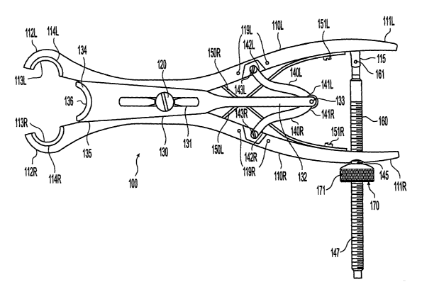
[0011) FIG. 1 is a bottom view of an embodiment of a multiple-blade retractor
according to the present invention;
[0(1121 FIG. 2 is a side view of the multiple-blade retractor of FIG. 1 in a
closed
position;
CA 02535391 2006-02-09
WO 2005/016131 PCT/US2004/026750
[0013] FIG. 2A is a partial cross-sectional view through a blade of the
multiple-blade
retractor of FIG. 2.
[0014) FIG. 3 is a side view of the multiple-blade retractor of FIG. 1 in an
open
position;
[0015] FIG. 4 is a side view of an alternative embodiment of a mufti-blade
retractor;
[4016) FIG. 5 is a partial perspective view of another embodiment of a
multiple-blade
retractor with detachable blades;
[001'11 FIG. 6 is an end view of a telescoping retractor blade;
[~lgl FIG. 7 is a side view of the inside face of the telescoping retractor
blade of
FIG. 6;
[0019] FIG. 8 is a side view of the outside face of the telescoping retractor
blade of
FIG. 7;
[0020) FIG. 9 is a partial bottom view of a blade of the multiple-blade
retractor of
FIG. 1 with a cannula for attaching a tool;
[0021] FIG. 10 is a perspective view of an embodiment of the multiple-blade
retractor
of FIG. 1 with an attachment for a tool;
[0022) FIG. l0A is a perspective view of another embodiment of the multiple-
blade
retractor with connecting portions;
[0023) FIG. 11 is a bottom view of another embodiment of a multiple-blade
retractor
with a biasing member and support members;
[0024) FIG. 12 is a cross-sectional view of the multiple-blade retractor of
FIG. 11
along A-A;
f~25] FIG. 13 is a detail view of a support member of the multiple-blade
retractor of
FIG. 11 along B-B;
4
CA 02535391 2006-02-09
WO 2005/016131 PCT/US2004/026750
[0026] FIG. 14 is a detail of an embodiment of a multiple-blade retractor with
a
tension limiting device in a first position;
[0027] FIG. 15 is a detail of the embodiment of the multiple-blade retractor
of FIG.
14 with the tension limiting device in a second position;
[0028] FIG. 16 is a detail of an embodiment of a multiple-blade retractor with
an
alternative tension limiting device in a first position;
[0029] FIG. 17 is a detail of an embodiment of the multiple-blade retractor of
FIG. 16
with the alternative tension limiting device in a second position;
[0030] FIG. 18 is a top view of another embodiment of a multiple-blade
retractor with
a fourth blade;
[0031] FIG. 19 is a partial side view of the multiple-blade retractor of FIG.
18;
[0032] FIG. 20 is a top view of an alternative fourth blade attachment of the
multiple-
blade retractor of FIG. 18;
[0033] FIG. 21 is a bottom view of another alternative embodiment of a
multiple-
blade retractor with an alternative fourth blade attachment;
[0034] FIG. 22 is a top view of an alternative fourth blade attachment of the
multiple-
blade retractor of FIG. 21;
[0035] FIG. 23 is a bottom view of another alternative embodiment of a
multiple-
blade retractor with another alternative fourth blade attachment; and
[0036] FIG. 24 is a bottom view of another alternative embodiment of a
multiple-
blade retractor with another alternative fourth blade attachment.
DETAILED DESCRIPTION
[0037] The retractor described in FIGS. 1-24 may be used to perform surgical
procedures in the spinal area including, but not limited to, discectomy,
implant insertion,
CA 02535391 2006-02-09
WO 2005/016131 PCT/US2004/026750
pedicle screw placement, and spinal rod placement. While the description of
the retractor
will be discussed primarily in relation to spinal surgery, it should be
understood that the
retractor of this invention may be used in other types of surgical procedures.
For instance,
the retractor may be used where a surgeon wishes to gain access within the
body by cutting
the skin and may provide an access location for surgical procedures performed
on a patient
using surgical instruments. In particular, the retractor may hold back soft
tissue or organs to
allow visibility and/or access for surgical instruments to the location in the
patient's body to
be operated on by a surgeon and may maintain an incision in a spread apart
position so that
surgical instruments can be inserted into a patient.
[~3$] Moreover, the components of any retractor embodiment discussed herein
may
be made, for example, of metal, plastic, rubber, or combination or composite
materials (i.e., a
material made of two or more materials). For example, the components may be
made from
stainless steel, titanium, aluminum, an alloy, carbon fiber composite, or a
polymer (e.g.,
polyvinyl chloride (PVC), polyethylene, polyesters of various sorts,
polycarbonate, teflon
coated metal, polyetherether ketone (PEEK), ultra high molecular weight
polyethylene
(UHI11~IWWPE)). In addition, various methods may be used to make the
components of the
retractors discussed above, including casting, extrusion, injection molding,
compression
molding, forging, machining, or transfer molding. And, the components may be
joined
together, for example, by gluing, casting or forging as a single piece,
welding or brazing, or
mechanically joined by screwing, riveting, or other appropriate means.
[0039] Referring now to FIG. 1, the multiple-blade retractor 100 may comprise
at
least two elongated portions 1 lOR and 110L. It should, however, be understood
that those of
ordinary skill in the art will recognize many modifications and substitutions
may be made to
various elements of the retractor 100.
CA 02535391 2006-02-09
WO 2005/016131 PCT/US2004/026750
[0040] The elongated portions 1108, 110L may have a proximal end closest to an
operator which may comprise handle portions 1118, 111L and a distal end
opposite the
proximal end which may comprise distal portions 1128, 112L. The handle
portions 1118
and 111L may be positioned at the proximal end of the elongated portions 1108
and 110L,
respectively, and may be designed to be grasped by a user. And, the distal
portions 1118 and
110L may be positioned at the distal end of the elongated portions 1108 and
110L,
respectively. Moreover, the elongated portions 1108 and 110L may be pivotally
connected,
for example, by a pivot connector 120. The pivot connector 120 may be a bolt
(with
matching nut), pin, rivet, or other similar means of providing a pivot point.
As such, the
handle portions 1118, 111L and distal portions 1128, 112L may move
reciprocally or
opposite relative to each other. When the handle portions 1118, 111L are drawn
together as
shown in FIG. 1, the distal ends 1128, 112L (and thus opposing blades 1138 and
113L) may
be spread apart.
[0041] The handle portions 111R,111L may have a grip 117 (FIG. 4) which may be
integral with or connectable to the handle portions 1118 and/or 111L and which
may
improve a user's grip of the retractor 100. The grip 117 may be made of the
same or different
material as the portions 1108, 110L. In one embodiment, the grip 117 may be a
piece of
material (e.~., plastic, rubber, etc.) positioned around the handle portions
1118, 111L. In
another embodiment, the grip 117 may be bumps, protrusions or grooves formed
on the
handle portions 1118, 111 L, which may be part of the structure of the handle
portions 1118,
111L or may be separate pieces positioned on the handle portions 1118, 111L.
For example,
FIG. 4 shows multiple pieces of material positioned on the handle portion
111L.
(0042] Blades 1138 and 113L may be attached to distal ends 1128 and 112L,
respectively, of elongated portions 1108, 110L. It should be understood that
any reference to
"blades" may not necessarily mean a cutting blade. While any blade described
herein may
CA 02535391 2006-02-09
WO 2005/016131 PCT/US2004/026750
have a cutting surface and/or may be used for cutting tissue, the retractor
blades preferably
function as walls that hold back soft tissue and prevent soft tissue from
entering a surgical
field. The blades 1138, 113L may be connected to the distal ends 1128, 112L,
respectively,
such that each blade 1138, 113L may move relative to the other blade 1138,
113L. In a
closed position, the distal ends 1128, 112L may be in contact with each other
and the blades
1138, 113L mounted on the distal ends 1128, 112L may define an initial
retractor opening as
shown in FIG. 10A. Depending on the shape and geometry of the blades 1138,
113L, the
opening may be a circular space; however, the opening may be any shape. As
shown in FIG.
1, blades 1138, 113L may have a concave-convex face profile, but blades having
other
configurations may also be used. Various factors may be considered when
determining the
design (e.g., size, shape, orientation) of the blades, including minimizing
the trauma to the
patient's body at the incision when the blades are spread apart, stabilizing
the blades in the
incision so they may not easily slip out of engagement with the retracted
tissue, and allowing
customization for each patient's anatomy.
f~431 A sliding bar 130 may be connected to the elongated portions 1108, 110L
by
pivot pin 120, which may be disposed through slot 131 of sliding bar 130. A
sliding blade
134, in turn, may be mounted on distal end 135 of sliding bar 130 such that
inner face 136 of
sliding blade 134 may be adjacent to outside faces 1148 and 114L of the blades
1138 and
113L, respectively. As with blades 1138 and 113L, the sliding blade 134 may
have a
concave-convex profile. Sliding blades 134 may have other co~gurations as
well.
«l The proximal end 132 of sliding bar 130 may be pivotally connected to
medial
ends 1418, 141L of links 1408, 140L by pin 133. Alternative connection
components may
be used in place of pin 133 (e.g., a screw, bolt) so long as the connection
component allows
for rotation of links 1408, 140L thereabout. Lateral ends 1428, 142L of links
1408, 140L
may be pivotally attached to elongated portions 1 lOR, 110L by screws 1438,
143L. It should
CA 02535391 2006-02-09
WO 2005/016131 PCT/US2004/026750
be understood that other connection components may be used in place of the
screws 1438,
143L (e.g., a pin, bolt) so long as the connection component allows for
rotation of links
1408, 140L thereabout. Holes 1198, 119L may also be provided in the elongated
portions
110R,110L to allow repositioning of the links 1408, 140L so that the movement
of the
sliding blade 134 may be adjusted with respect to the opposing blades 1138,
113L, as will be
described in greater detail below. The holes 1198, 119L may be threaded or
smooth. The
sliding blade 134 may be connected along any portion of the elongated portions
1108 and
110L by any direct or indirect method, including an intermediate linkage.
[0045] The links 1408, 140L may connect the sliding bar 130 and, consequently,
the
sliding blade 134 to the elongated portions 1108, 110L such that moving the
handle portions
1118, 111L together may result in the sliding blade 134 moving away from the
blades 1138,
113L by an amount proportional to the movement of the elongated portions 1108,
110L. If
an operator connects the links 1408, 140L to different holes 1198, 119L, the
amount the
sliding blade 134 may move away from the blades 1138, 113L relative to the
movement of
the elongated portions 1108, 110L may change. For example, connecting the
links 1408,
140L at a position on the elongated portions 1108, 110L closer to the pin 120
may result in
the sliding blade 134 moving a smaller distance away from the blades 1138,
113L than if the
links 1408, 140L were connected at a position on the elongated portions 1108,
110L farther
from the pin 120. Changing the position of the links 1408, 140L may also
affect the location
of the sliding blade 134 relative to the blades 1138, 113L when the retractor
100 is in a
closed position.
[0046] Moreover, leaf springs 1508, 150L may be positioned between the
elongated
portions 1 lOR, 1 lOL and may be connected to elongated portions 1108, 110L by
screws
1518, 151L. It should be appreciated by those skilled in that art that this
connection may
alternatively be made using rivets, welding or other fastening mechanisms. The
leaf springs
CA 02535391 2006-02-09
WO 2005/016131 PCT/US2004/026750
1508, 150L may bias the handle portions 1118, 111L in a spread apart position
such that the
retractor blades 1138, 113L and sliding blade 134 may be in the closed
position. In another
embodiment, a coil spring (not shown) may be used to bias the handle portions
1118, 111L in
a spread apart position. However, other components and different components
and
mechanisms may be used to bias the handle portions 1118, 111L apart.
(0(14'7] In use, as handle portions 1118, 111L are brought together, the links
1408,
140L may rotate about screws 1438, 143L such that medial ends 1418, 141L may
move in
the proximal direction (i.e., away from the blades 1138, 113L). As the medial
ends 1418,
141L move proximally, they pivot about pin 133 and pull the sliding bar 130
proximally.
The linear movement of the sliding bar 130 is guided by pivot pin 120
interacting with and
moving in slot 131. As sliding bar 130 moves proximally, sliding blade 134 may
move in the
proximal direction. Upon releasing pressure from the handle portions 1118,
111L, the leaf
springs 150R,150L may cause the handle portions 1118, 111L to spread apart. As
a result,
the elongated portions 1108, 110L and sliding blade 130 may return to the
closed position
where the blades 1138 and 113L may be in close proximity and the inside face
136 of sliding
blade 134 may be adjacent to the outside faces 1148, 114L of the blades 1138,
113L.
f 0(148] A locking mechanism may also be provided to lock the blades 1138,
113L and
134 at a selected distance from each other. As shown in FIG. 1, the locking
mechanism may
comprise a threaded bar 160 pivotally connected by a pin 161 to a flange 115
on the inner
side of handle portion 111L. The opposite end of threaded bar 160 may be
slidably received
within a bore 145 in handle portion 1118, such that a portion 147 of the
threaded bar 160
extends past handle portion 1118. A nut 170 may be threaded onto the portion
147 of
threaded rod 160 and may be tightened against the handle portion 1108, thereby
preventing
spreading of the handle portions 1 l OR, 1 l OL. The nut 170 may have an outer
knurled surface
171, which may enhance a user's grip on the nut 170 during tightening and
loosening of the
to
CA 02535391 2006-02-09
WO 2005/016131 PCT/US2004/026750
nut 170. Alternatively, the locking mechanism may be configured in the
opposite
arrangement so that the threaded bar 160 passes through the handle portion 1
lOL and the nut
170 engages the handle portion 110L. One skilled in the art would recognize
that the locking
mechanism can be a ratchet, a "soft lock" arrangement, or any other
appropriate locking
mechanism known in the art.
[0049) In the closed position, blades 1138, 113L, and 134 may generally form a
circular opening with an inside diameter between about 3 ~nm and about 50 mm,
more
preferably, between about 10 mm and 16 mm and, most preferably, about 13 rnm.
It should
be understood by those of skill in the art that the blades 1138, 113L, and 134
may be of any
size suitable to be inserted into a surgical incision in a patient undergoing
a surgical
procedure, and thereafter be spread apart to form an opening through which
medical
instruments may be inserted to perform exploratory, diagnostic, or surgical
procedures.
[0050] In the opened position, the blades 1138, 113L, and 134 may form an
access
opening - for example, a roughly triangular (e.g., isosceles triangle) or four
pointed opening
- having a dimension, for example, of between about 10 mm and about 150 mm by
between
about 10 mm and about 50 mm, and more preferably about 70 mm by about 30 mm.
The
opening may be other shapes and sizes depending on blade geometry and size.
Furthermore,
in the open position, the distance between the blades 1138 and 113L may be,
for example,
between about 10 mm and about 150 mm. The distance between the sliding blade
134 and
the blades 1138, 113L, for example, may be between about 0 rnm and about 50
mm.
[0051] As shown in FIGS. 2 and 3, the blades 113L and 134 may have outwardly
flared tips 116L and 137 with radii R to facilitate soft tissue engagement.
The blade 1138
may also have a flared tip (not shown) with a radius R. It should be
understood that a flared
tip may be any type of curve or angle. In one embodiment, the flared tips may
be at an angle
with the wall of the blades. For example, with reference to blade 134 in FIG.
2A, the flared
11
CA 02535391 2006-02-09
WO 2005/016131 PCT/US2004/026750
tip 137 may be at an angle 118 with a wall 134b of the blade 134. The angle
118 may, for
example, be between about 90 and about 180° and, more preferably,
between about 135 and
about 180°. One or more blades may have a flared tip or no blade may
have a flared tip. In
another embodiment, some blades may have a radius R, while other blades may
have an
angle 118. In yet another embodiment, all blades may have radii R or all
blades may have an
angle 118. And, the radius R and/or angle 118 of each blade may be the same as
or different
from the radius R and/ or angle 118 of the other blades. It should also be
understood that any
blade may be flared or angled along its entire length. A flared tip may
facilitate soft tissue
engagement (i.e., enhance the grip on the underside of a patient's tissue)
and, thus, may
prevent inadvertent or premature dislodging or slipping of the retractor 100
from an incision.
A flared tip such as tips 116L and 137 may also be used to adapt the retractor
100 to the bony
anatomy of the spine.
[0052] Moreover, the blades 1138, 113L and 134 may take on various shapes and
sizes depending on the surgical procedure in which the retractor is to be
used. The tips of the
blades 1138, 113L and 134 may be adapted to conform to the bony anatomy of the
spine.
For example, the blades 1138, 113L and 134 may be configured to contact a
portion of a
spinal lamina.
[0053) To achieve this conformity, the angle a of tip 137 of the sliding blade
134 may
be between about 0 and about 70° and, more preferably, between about 20
and about 40°.
The angle /3 of the tip 116L of the blade 113L and the tip (not shown) of the
blade 1138 may
be between about 0° and about 80° and, more preferably, about
30° and about 60°. The
lengths of the blades 1138, 113L (including the angled tips) may be between
about 25 mm
and about 200 mm and, more preferably, between about 80 mm and about 110 mm.
Radii R
at the flaring ends of blades 1138, 113L and/or 134 (where concave-convex
blades are
provided) may be between about 0 mm and about 100 mm and, more preferably,
between
12
CA 02535391 2006-02-09
WO 2005/016131 PCT/US2004/026750
about 0 mm and about 50 mm. The blades 1138, 113L and/or 134 may be curved
from their
distal tips and the curve may extend for a length of between about 0 mm and
about 30 mm of
the blades 1138, 113L and/or 134 and, more preferably, for about the distal 0
mm to about 20
mm of the blades 1138, 113L and/or 134. And, the blades 1138, 113L, and blade
134 may
be approximately the same length or they may be of different combinations of
lengths, as is
appropriate for a particular procedure and patient.
[0054] For example, as shown in FIGS. 2 and 3, the sliding blade 134 may be
longer
than the blades 1138, 113L. In such a configuration, the retractor 100 may
function as a
lateral retractor. As a lateral retractor, for example, when a patient is
laying on his/her
stomach, the retractor 100 may be positioned so that the handle portions 1118,
111L of the
retractor 100 may be at an angle (e.g., approximately perpendicular) with the
spine of a
patient or otherwise pointing towards the side of a patient. In this
orientation, the blades
1138, 113L may be positioned over the spine and, because of their shorter
length, may avoid
contact with spinal bones. The longer sliding blade 134 may be positioned
along the side of
the spine and may penetrate deeper into the back of a patient.
[0055] As shown in FIG. 4, in another embodiment, the sliding blade 134a may
be
shorter than the blades 113L, 1138. In such a co~guration, the retractor 100a
may function
as a medial retractor. As a medial retractor, for example, when a patient is
laying on his/her
stomach, the retractor 100a may be positioned so the handle portions 1118,
111L of the
retractor 100a may be parallel to the spine of a patient. In this orientation,
the sliding blade
134 may be positioned over the spine and, because of its shorter length, may
avoid contact
with spinal bones. On the other hand, the longer blades 1138, 113L may be
positioned along
the side of the spine and may penetrate deeper into the back of a patient.
[005 Moreover, the blades 1138, 113L and/or 134 of the retractor 100 of FIGS.
1-3
may be permanently attached to the elongated portions 1108, 110L or sliding
bar 132,
13
CA 02535391 2006-02-09
WO 2005/016131 PCT/US2004/026750
respectively, by, for example, welding, brazing, soldering or may be formed
integrally with
the elongated portions 1108, 110L or sliding bar 132. In an alternate
embodiment, shown in
FIG. 5, blades 2138, 213L and/or 234 of the retractor 200 may be detachable.
Detachable
blades may allow a surgeon to install blades of various lengths, shapes,
and/or materials to
account various factors, including the differences in patient anatomy, part of
the body where
surgery may be performed, and whether radiolucence may be desireable.
[0057] The blades 2138, 213L, and 234 may have protrusions 2178, 217L, and
238,
respectively. Grooves 2188, 218L, and 239 may be provided in protrusions 2178,
217L, and
238 to mate with ball detents (not shown), which may be positioned within the
holes 2818,
281L, and 280. The ball detents may comprise, for example, ball bearings (not
shown)
operatively connected to a biasing means (e.g., a spring) such that the ball
bearings may
move in and out of holes 2818, 281L and 281 to engage/disengage the grooves
2188, 218L,
and 239. The holes 2818, 281L, and 281 may be located in distal portions 2128,
212L of
elongated portions 2108, 210L and in the sliding bar 235. In alternative
embodiments, other
means of removably attaching the blades 2138, 213L and/or 234 may be used,
such as
threaded connections, set screws, pins, etc. The blades 2138, 213L and/or 234
may freely
rotate with respect to the elongated portions 2108, 210L and/or the sliding
bar 235 or may
have keyed connections with the elongated portions 2108, 210L and/or the
sliding bar 235 to
maintain a fixed relative orientation between the blades 2138, 213L and/or 234
and the
elongated portions 2108, 210L and/or the sliding bar 235.
[0058] As shown in FIGS. 6-8, in another embodiment of the present invention,
the
retractor 100 may comprise a variable length telescoping retractor blade 313.
Variable length
blades may allow a surgeon to select the length of each blade to account for
differences in
patient anatomy or the type of surgery to be performed while minimizing the
inventory of
blades that would be required if detachable blades were used. The telescoping
retractor blade
14
CA 02535391 2006-02-09
WO 2005/016131 PCT/US2004/026750
313 may comprise an upper blade portion 3131 and a lower blade portion 3132.
The lower
blade portion 3132 may be positioned within upper blade portion 3131 and may
slide axially
therein. The upper blade portion 3131 may comprise lips 3134, which may
encircle outer
edges 3135 of the lower blade portion 3132. Such a construction may prevent
all motion of
the lower blade portion 3132 in relation to the upper blade portion 3131
except in an axial
direction. The engaging portion 3133 may extend through a hole (not shown) in
upper blade
portion 3131 and may be selectively engaged in one of a series of linearly
disposed
depressions 3136 in lower blade portion 3132. In one embodiment, holes through
the lower
blade portion 3132 may be used in place of or in addition to the depressions
3136. Thus, the
lower blade portion 3132 may be fixed in relation to the upper blade portion
3131. In one
embodiment of the present invention, the engaging portion 3133 may be a screw
positioned
within a threaded hole (not shown) in the upper blade portion 3131.
[0059] The lower blade portion 3132 may be slid axially (i.e., up or down)
within the
upper blade portion 3131 to adjust the length of the telescoping blade 313.
Thereafter, the
position of the two blades rnay be locked by positioning the engaging portion
3133 in the
appropriate depression 3136. It will be understood that any other means of
locking the lower
blade portion 3132 to the upper blade portion 3131 may be used so long as the
position of the
blades relative to one another may be adjustable. For example, locking the
lower blade
portion 3132 to the upper blade portion 3131 may include the use of a ratchet
means, a
friction fit, or a leaf spring or ball detent in one blade portion engaging
one of a selectable
variety of depressions in the other blade portion.
[0060] In general, various factors may be considered when determining the
material
used to make any of the retractor blades discussed above, including the
ability to withstand
sterilization/cleaning (i.e., cleaning products used in sterilization in a
hospital), weight,
durability, mechanical strength (e.g., the ability to withstand stress from
opening the retractor
is
CA 02535391 2006-02-09
WO 2005/016131 PCT/US2004/026750
in a patient's body and maintaining the retractor in an open position),
resistance to bacterial
formation, ease and cost of manufacturing, biocompatiblility and ability to
withstand staining
(i.e., from blood or other chemical products used in a hospital). Moreover,
using a non-
metallic blades (or, for that matter, any other component) may provide the
benefit of the
blade being radiolucent (i.e., transparent to x-rays or other form of
radiation), which may
allow better visualization of the surgical site using current imaging
techniques. In addition,
the blades or any other component of the retractor may include a non-glare
surface finish,
which may prevent light reflection and improve visualization in the surgical
working space,
and/or a scratch resistant coating, which may preserve the surface
finish/coating.
[0061] Further, the outside faces of the retractor blades may be partially or
fully
padded or comprise a compressible material to minimize trauma to the
surrounding tissue as
the retractor is spread open. Thus, the retractor blades may be constructed of
multiple layers
- an inner layer which may be constructed of a stronger, stiffer material and
an outer layer
which may be spongy or padded. In one embodiment of the present invention, one
layer may
be sprayed onto another layer. The layers may be connected together, for
example, by a
bonding medium (e.g., adhesive), screws, pegs, bolts, or welding.
[0062) Turning now to FIG. 9, one or more of the blades 1138, 113L or 134 of
retractor 100 may have a cannula 1341, which may be used to attach a device
for use during
surgery, for example, a light source, suction/irrigation tool, or viewing
device. The cannula
1341 may extend only a short length along the blades 1138, 113L and/or 134 or
may extend
the entire length of the blades 1138, 113L and/or 134. Moreover, the cannula
1341 may be
located at any position along the length of the blades 1138, 113L and/or 134
and may be any
diameter appropriate for attaching tools, such as a light source,
suction/irrigation
instrumentation, or any other instrumentation required by the specific
surgical procedures.
Although not shown, the light source may comprise a fiber-optic bundle, and
this bundle may
16
CA 02535391 2006-02-09
WO 2005/016131 PCT/US2004/026750
be inserted within one of the cannulae 1341. Alternatively, the light source
may be integrated
into the blades 1138, 113L and/or 134, either being formed together with the
blades or glued
or otherwise bonded to the blades.
[~3] Other means of attaching a surgical instrument are also envisioned. For
example, as shown in FIG. 10, a movable arm 1000 may be attached to elongated
portions
1108 and/or 1 lOL. A surgical instrument, for instance, a microscope or other
similar
viewing device may be removeably or permanently connected to the moveable arm
1000.
The moveable arm 1000 may be bolted or clamped onto elongated portions 1108
and/or
110L and may be releasably attached and/or moveable along elongated portions
1108 and/or
110L. The moveable arm 1000 may alternatively be permanently attached to
elongated
portions 1108 and/or 110L. The moveable arm 1000 may be a ball and socket type
articulating arm, flexible arm, or other device allowing an instrument to be
attached and
moved relative to three-blade retractor 100.
[0064] In the embodiment of FIG. 10A, a retractor 200 may comprise one or more
connection portions 202, which may be used to engage a support structure (not
shown). The
support structure, which may be rigid or flexible (e.g., flex arm), and may,
in turn, be
connected, for example, to an operating table to hold the retractor 200 in
place relative to a
patient during surgery. The connection portion 202 may be any shape or size
and may have
an opening 204 to receive another component (not shown). Alternatively, the
connection
portion 202 may have no opening 204. Moreover, the connection portion 202 may
have a
clip or hook (not shown) to engage a clip or hook engaging portion of another
component
(not shown). The connection portion 202 may be integral with or a separate
piece
connectable to the retractor 200. It should, however, be understood that any
construction of
the connection portion 202 is envisioned so long as the connection portion 202
may be used
to connect the retractor 200 to another component.
17
CA 02535391 2006-02-09
WO 2005/016131 PCT/US2004/026750
f~51 Another embodiment of the retractor is shown in FIGS. 11-13. The
retractor
500 may operate similar to the retractor 100 of FIGS. 1-3. And, similar to the
retractor 100,
the construction of the retractor 500 may permit the stroke of a sliding blade
534 to be varied
in relation to the movement of the blades 5138 and 513L. This may provide the
advantage of
enabling an operator to vary the dimensions of the surgical opening depending
on the
requirements of the procedure. Specifically, a plurality of pairs of recesses
5198, 519L may
be provided for selectively locating lateral ends 5428, 542L of links 5408 ,
540L to vary the
stroke of a sliding bar 530 in relation to a given movement of elongated
portions 5108, 510L.
The lateral ends 5428, 542L of the links 5408 , 540L may be pivotally attached
to the
elongated portions 5108, 510L by integral pins 5448, 544L, which may be
positioned in
recesses 5198, 519L. The integral pins 5448, 544L may be topped by integral
caps 5458,
545L which may help retain the pins 5448, 544L within the recesses 5198, 519L.
Positioning the pins 5448, 544L in a pair of recesses 5198, 519L that are
closer to a pivot pin 520 may result in the pins 5448, 544L being moved a
shorter distance
away from one another for a given movement of the elongated portions 5108,
510L. Such a
positioning of the pins 5448, 544L may also result in reduction in the angle
between the links
5408 , 540L. These factors may result in a shorter stroke of the sliding blade
534.
Conversely, a longer stroke of the sliding blade 534 may result where the pins
5448, 544L
are positioned in a pair of recesses 5198, 519L that are closer to the pivot
pin 520. For
example, the stroke of the sliding blade 534 may be about 10 mm when the
integral pins
5448, 544L are inserted into the recesses 5198, 519L closest to the pivot pin
520 and about
20 mm when the integral pins 5448, 544L are inserted into the recesses 5198,
519L farthest
from the pivot pin 520.
1006'1] In addition, a coil spring 555 may encircle a pin 533 and coil spring
ends
5568, 556L may engage the side of the links 5408, 540L closest to the pivot
pin 520. The
is
CA 02535391 2006-02-09
WO 2005/016131 PCT/US2004/026750
bias of spring 555 may act to keep integral pins 5448, 544L within recesses
5198, 519L as
well as bias the handle portions 5118, 511L of elongated portions 5108, 510L
apart. The
coil spring 555 may also be used in conjunction with one or more leaf springs
(discussed
above and shown in FIG. 1) to bias handle portions 5118, 511L apart.
[0068] The retractor may also comprise support members 5908, 590L as shown in
FIGS. 11 and 13. The support members 5908, 590L may be used to support the
retractor 500
on a patient's body after the blades 5138, 513L and 534 have been inserted
into the patient.
Upon insertion, the weight of handle portions 5118, 511L may cause the handle
portions
5118, 511L to tip towards the patient, which may cause the blades 5138, 513L
and/or 534 to
move within a patient. The support members 5908, 590L may by extended and may
rest
upon the patient's body to oppose any movement created by the weight of handle
portions
5118, 511L. And, the support members 5908, 590L may be pivotally mounted on
elongated
portions 5108, 510L by screws 5918, 591L; however, rivets or other means of
providing a
pivoting connection may also be used instead of the screws 5918, 591L.
Moreover, the
support members 5908, 590L may have feet 5928, 592L which may rest on a
patient's body
when the support members 5908, 590L are pivoted an angle (e.g., 90°) in
relation to
elongated portions 5108, 510L. As shown in FIG. 13, recessed portions 593L,
594L and
similar recess portions on elongate portion 5108 (not shown) may be provided
within
elongated portions 510L, 5108 to provide a stowed location (e.g., when 590L is
positioned in
recess 593L) and a separate deployed location (e.g., when 590L is positioned
in recess 594L)
for the support members 590L, 5908. These recesses may be oriented either
parallel or at an
angle (e.g., perpendicular) to elongated portions 510L, 5108 and may serve to
provisionally
Iock the support members 5908, 590L in their stowed or deployed positions.
[0069] The retractor may also comprise a sliding blade tension limiting
device, such
as shown in FIGS. 14 and 15. In this embodiment, a spring 5322 may be
connected to the
19
CA 02535391 2006-02-09
WO 2005/016131 PCT/US2004/026750
third blade sliding bar 530 and may limit the amount of force placed on the
tissue by the third
blade 534 (FIG. 11) during retraction. If the force applied to the tissue
being retractor is
greater than the spring force, the spring may extend and the third blade 534
may remain
stationary or may move only a slight amount, thus reducing the likelihood of
tissue damage.
For the retractor of this embodiment, the sliding bar 530 may comprise a
shortened proximal
end 5320 having an attachment means 5321 (e.g., a loop) for attaching to a
distal end 5323 of
a coil spring 5322. A proximal end 5324 of the spring 5322 may be attached to
a connector
5390 by a second attachment means 5391 (e.g., a loop). A pin 533 may pivotally
connect the
connector 5390 to the links 5408, 540L. So, when the handle portions 5118,
511L are
brought together, the third blade 534 may move towards the proximal end of the
retractor 500
until the force on the tissue exceeds a predetermined value (corresponding to
a selected
spring size). At a point after the force on the tissue equals the spring
force, the spring may
stretch and the blade 534 may remain stationery or may move only slightly.
Such a
construction may prevent tissue damage. This predetermined maximum tissue
force may be
controlled by providing the surgeon with a variety of springs to select from,
prior to
performing the procedure.
In an alternative embodiment, a sleeve 5392 may be provided to allow the
sliding blade tension limiting device to be overridden by creating a fixed
link between the
sliding bar 530 and the connector 5390. The sleeve 5392 may have a proximal
circumferential slot 5393 and a distal circumferential slot 5325. A pin 5395
on the connector
5390 may retain the sleeve 5392 on the connector 5390 by engaging a slot 5393,
while still
allowing the sleeve 5392 to be rotated about the connector 5390. A
longitudinal slot 5326
may allow a distal end 5396 of the sleeve 5392 to be slid over a pin 5327 on
the proximal end
5320. The sleeve 5392 may then be rotated so that it may be retained on the
proximal end
5320 of the sliding bar 530. In this configuration, shown in FIG. 15, the
sliding bar 530 and
CA 02535391 2006-02-09
WO 2005/016131 PCT/US2004/026750
the connector 5390 may be held in a fixed relationship so that the retractor
may operate
similar to the retractor 100 of FIGS. 1-3. While a sleeve is shown as a means
of removably
providing a nonelastic bridge over the gap between the sliding bar 530 and the
connector
5390, other means are also envisioned including, for example, a screw which
may be
removeably or permanently fixed to the connector 5390 and may be screwed into
a portion
the sliding bar 530 (i.e., engaged or disengaged) or vice versa such as
discussed below.
[0071] FIGS. 16 and 17 illustrate an alternative means for limiting the force
applied
to an incision by the sliding blade 530. A horizontal member 5328 may be
attached to the
proximal end of the sliding bar 530 and may have at its proximal end a
threaded receiving
member 5329. The member 5396 may extend from the pin 533 to a vertical member
5397.
A spring 5322 may connect the vertical member 5397 and the threaded receiving
member
5329 to limit the force applied to an incision by the third blade 534 in the
same manner as the
sliding blade tension limiting device shown in FIG. 14.
[0072] The force limiting device of FIGS. 16 and 17 may be overridden. The
vertical
member 5397 may have a through hole 5400 and the receiving member 5329 may
have a
threaded hole 5402. A connecting component 5398 (e.g., a screw) may be
inserted through
the hole of the vertical member 5397 and threaded into the threaded hole of
the receiving
member 5329. Thus, the member 5396 may be fixed with respect to the sliding
bar 530. It
should be noted that other methods and mechanisms may be used to limit the
force applied to
an incision by the sliding blade 534. Likewise, other arrangements may be used
to override
such tension limiting mechanisms.
[0073] FIGS. 18 and 19 show an embodiment of a retractor 600 with a detachable
and
independently moveable fourth blade 690 which may be located opposite a
sliding blade 634.
While shown as detachable, fourth blade 690 may also be permanently attached.
The
detachable fourth blade 690 may allow a surgeon to further vary the shape and
dimensions of
21
CA 02535391 2006-02-09
WO 2005/016131 PCT/US2004/026750
the opening created by the retractor 600. The fourth blade 690 may be attached
to slotted
arms 6918, 691L by pivot pins 6928, 692L. However, other means of attaching
the fourth
blade 690 to the retractor 600 are also envisioned. In addition, the fourth
blade 690 may have
all the features of the previously described blades. For example, the fourth
blade 690 may
have a flared end, may be adjustable similar to the blade 313 (FIGS. 6-8) or
may have a
cannula similar to cannula 1341 (FIG. 9). Screws 6938, 693L, which extend
through slots
6948, 694L of the arms 6918, 691L, may be used to attach the arms 6918, 691L
to the
elongated portions 6108, 610L. The screws 6938, 693L may be threaded into
thread holes
(not shown) in the elongated portions 6108, 610L. Other components such as
bolts may be
used in place of the screws 6938, 693L. It will be apparent to those skilled
in the art that any
method of connecting the fourth blade 690 to the retractor 600 is envisioned.
[0074) In use, a surgeon may loosely attach the arms 6918, 691L to the
elongated
portions 6108, 610L using screws 6938, 693L. Thereafter, the surgeon may open
and lock
the retractor 600 within the patient and may manually move the fourth blade
690 into a
desired position. The fourth blade 690 may be held in the desired position
while the screws
6938, 693L are rotated until the arms 6918, 691L are locked in position. Thus,
a four-
pointed square or roughly circular opening may be formed. The dimension from
the blade
6138 to the blade 613L, for example, may be between about 10 mm and about 150
mrn.
And, the dimension from the sliding blade 634 to the fourth blade 690 may be
between about
mm and about 70 mm.
[0075] FIG. 20 shows an alternative means of connecting the fourth blade 690
to the
retractor 600. Rather than having pivot points at each end, the blade 690 may
have a single
pivot 692 at its center and a unitary arm 691 which may have slots 6948, 694L.
The
arrangement shown in FIGS. 20 may be used in the same way as described above
with regard
to FIGS. 18 and 19. But, unlike the arrangement show in FIGS. 18 and 19, the
fourth blade
22
CA 02535391 2006-02-09
WO 2005/016131 PCT/US2004/026750
690 of FIG. 20 may be allowed to pivot after arm 691 is locked. Alternatively,
the pivot 692
may be fixed so that the fourth blade 690 is held in place.
[0076] FIGS. 21 and 22 show another embodiment of a retractor 700 comprising a
fourth blade 790, which may be permanently attached to or detachable from the
retractor 700.
The fourth blade 790 may be connected to the arm 791 by, for example, welding,
brazing, or
mechanical connectors such as rivets or screws (not shown). The arm 791, in
turn, may be
attached to tabs 7958, 795L on elongated portions 7108, 710L by connectors
7938, 793L.
The connectors 7938, 793L may slide within the slots 7948, 794L in arm 791.
Various
components may be used as connectors 7938, 793L, including a pin, screw, or
bolt.
[0077] In use, a surgeon may loosely attach the arms 791 to the elongated
portions
7108, 710L using connectors 7938, 793L. After opening and locking the
retractor 700, the
surgeon may manually move the fourth blade 790 into position (e.g, by moving
the arm 791
back and forth so that the connectors 7938, 793L move within the slots 7948,
794L) and
hold the blade 790 in position while tightening the connectors 7938, 793L.
After the
connectors 7938, 793L are fully tightened, the fourth blade 790 may be locked
in position.
The fourth blade 790 may have all the features of previously described blades
including, for
example, a flared end, adjustability (e.g., similar to the blade 313 of FIGS.
6-8), and may also
have a cannula for holding various instruments (FIG. 9).
[0078] As shown in FIG. 22, the arm 791 may have angled portions 7968, 796L
rather than the straight arm 791 of FIG. 21. The angled portions 7968, 796L
may allow the
fourth blade 790 to move in a distal direction as the handle portions 7118,
711 L are brought
together or a proximal direction as the elongate portions 7108, 710L move
apart from each
other. The angled portions 7968, 796L may be various lengths and form various
angles in
relation to each other to allow for a wide range of movement.
23
CA 02535391 2006-02-09
WO 2005/016131 PCT/US2004/026750
(00791 FIG. 23 shows an embodiment of a retractor 800 with a fourth blade 890,
which may move as the other blades are moved. Elongated portions 8108, 810L
may have
extension arms 8978, 897L, which may be integral with the elongated portions
8108, 810L
or with may be removeably attached to the elongated portions 8108, 810L by
screws or other
appropriate mechanical means. The extension arms 8978, 897L may be connected
to arms
8988, 898L, which may pivot about pins 8938, 893L. Additionally, the arms
8988, 898L
may be pivotally attached to a member 899 at a central pin 893C. And, the
blade 890 may be
attached to member 899 by, for example, welding, brazing, or a mechanical
connection (e.g.,
a rivet, screw, bolt, etc.). In use, handle portions 8118, 811L of elongated
portions 8108,
810L may be brought together and the pins 8938, 893L may move farther apart.
As a result,
the arms 8988, 898L may pivot about the pins 8938, 893L, thereby moving the
member 899
along with the fourth blade 890 away from a sliding blade 834. The movement of
the fourth
blade 890 may make the retractor 800 easier to use than the retractors of
FIGS. 18-22 (i.e.,
does not require the surgeon to perform the addition step of adjusting the
fourth blade). The
retractor 800 may, however, be less flexible in use since the blades are in a
set relationship
with respect to each other. The fourth blade 890 may have all the features of
previously
described blades including, for example, a flared end, adjustability (e.g.,
similar to the blade
313 of FIGS. 6-8), and may also have a cannula for holding various instruments
(FIG. 9).
f~801 FIG. 24 illustrates another retractor 900 where a fourth blade 990 may
move
as the other blades move. The elongated portions 9108, 910L may have extension
arms
9978, 997L. As handle portion 9118, 911L are brought together, an arm 998 may
pivot
about a pin 993L at the distal end of the extension arm 997L and a pin 9938
may slide within
a slot 994 of the arm 998. The movement of the arm 998 may result in the
fourth blade 990,
which may be attached to the arm 998 by a pin 993C, moving in a distal
direction, away from
24
CA 02535391 2006-02-09
WO 2005/016131 PCT/US2004/026750
a sliding blade 934. The fourth blade 990 may pivot about the pin 993C or may
be fixed with
respect to the arm 998.
[0081] Furthermore, the retractors described herein may be provided as an
individual
component, or it may be provided as part of a kit. A kit may include one or
more of the
retractors described herein, and one or more two-bladed retractors or two-
bladed hinged
retractors. The two-bladed and two-bladed hinged retractors may be obtained
from any
number of fabricators of medical instruments. As part of a kit, the retractor
may be provided
with a multiplicity of interchangeable blades comprising various lengths,
materials, and
surface configurations, as well as various springs for the force-limiting
sliding blade
embodiments. A kit may also contain a light source, suction/irrigation tool,
flat blades,
blades of various lengths, and blades of various engagement angles.
[0082] While the foregoing description and drawings represent the preferred
embodiments of the present invention, it will be understood that various
additions,
modifications and substitutions may be made therein without departing from the
spirit and
scope of the present invention as defined in the accompanying claims. In
particular, it will be
clear to those skilled in the art that the present invention may be embodied
in other specific
forms, structures, arrangements, proportions, and with other elements,
materials, and
components, without departing from the spirit or essential characteristics
thereof. One skilled
in the art will appreciate that the invention may be used with many
modifications of structure,
arrangement, proportions, materials, and components and otherwise, used in the
practice of
the invention, which are particularly adapted to specific environments and
operative
requirements without departing from the principles of the present invention.
The presently
disclosed embodiments are therefore to be considered in all respects as
illustrative and not
restrictive, the scope of the invention being indicated by the appended
claims, and not limited
to the foregoing description.
2s