Note: Descriptions are shown in the official language in which they were submitted.
CA 02535462 1997-05-06
-1-
METHOD FOR REUSING HANGERS WITH SIZE INDICIA
This application is a division of copending
Canadian Patent Application Serial No. 2,204,592, filed May
6, 1997.
Fi c1 ri of tha Tncranti nn
The present invention is directed to the field of
garment hangers and is more particularly directed to a
method for reusing hangers with size indicia mounted
thereon. There is also disclosed a method and system for
hanging and color coding clothing on display to assist
consumer groups in locating clothing appropriate to their
physiology.
Background of the Invention:
An article of clothing typically includes one or
more labels located somewhere inside of the clothing
article. The label usually includes size, fiber content and
manufacturer details as well as information relating to
country of origin and care instructions. In addition, a tag
is attached to the article of clothing identifying the price
of the garment as well as size. The tag often includes
additional information relating to the store name,
manufacturer and possibly a bar code which when scanned
2J provides such information.
In some cases a particular retailer or garment
manufacturer has attached a further tag to the garment which
bears a design that is in part colored to permit sorting
according to some attribute of the garment such as style,
color or size. For instance, the portion of the design that
is colored may be blue to indicate a women's size 6 or green
to indicate a women's size 8 or blue to indicate a men's
size 44 or
CA 02535462 1997-05-06
-2-
green to indicate a men's size 48. When such
1 information is included on the tag attached to a
garment, the consumer or retailer need IlOt review the
label of each item of clothing but merely locate the
appropriately colored tag.
However, tags are often attached to either
the front, back or sleeve of the garment and thus, are
not readily visible to either the retailer or the
consumer. The retailer or consumer must rifle through
the garments on the raclc to locate the tags with the
IO pertinent information. If the garment is not hung on
a rack but folded in staclts (as is typical with
sweaters and jeans) the tags are often tucked inside
the garment for purposes of a neater display, thus, it
is necessary to unfold the garment to find the
appropriate information.
Furthermore, there is virtually no
uniformity between manufacturers and/or retailers as
to the designation of the desired attribute of the
clothing. For instance, the color blue may mean size
6 for one manufacturer or retailer but size 12 for
another. Thins, the consumer is not aided by the color
designation when visiting different areas of the
store. Further, blue may refer t.o large in a men's
jacket size but medium for men's slacks.
E~'or purposes of displaying garments
suspende<~ on In<~rrgers i.n an orderly and art_ractive
manner to the neta.il customer, i t: is often <.lesi .r_ed Lo
atfi.x an i r~di cat:i.ng means on the hanger i n a posi-ti on
visible to the retail customer whi 1e the hanger i:;
35
CA 02535462 1997-05-06
suspended on a rac~k. The indicating means identifies
some attribute of the garment suspended from the
hanger, such as s:i ze, quali i.y, color, rnanufacturi_ng
data, or ~mU.~ter-n.
Tloe provision of a readily v~ si)~le size
indicator on a garment hanger i.s now accepted by
retailers as a des.irak7le addition too a garment hanger.
'2'o accommodate thc-' various types of hanger: avai cable
in t_he industry numerous indicating mearos Gave been
clevelope.l in a variel;y of shapes, sizes and materials.
Sirni.l_arIy, trangers have been developed to accommod,-ate
a varpety of dir~ferent .indicating means.
Ire llustralian Patent ado. 638436 and
eorresponc~inc~ U.S. 1'a tent No. 5, 388, 354, assigned to
ttae a ssignee of t=the ~~resent invent.ioro, a 7 ow-profile
molded plastic; i.nc:licator for a garment hanger which
re<~uires lirni.ted mod:if=ication to tare book of the
hanger to er~~rl~le the i.ndicat.;or to be sec,ure~ y att ached
to the trop of t;he hook where c t is mast vi Bible c s
described. The indicator is also designed to enable
sart:ing into a prtedetermineci orientation to enable
automated harrciling anc:l fitt.i.ng of t_he indi_catc.>rs t.o
hangers as described in t,J.S. Patent Nos. 5,272,806 anti
5, 285, 566 wh i.cln are assicaned to the assignee c:~fi the
present invention.
much tuangers and indicia are t:yp.ically used
only a single t_pme and then shippe~~l t:o either a
1_andfill as wast:.e or a recyc:l.ir~g center where the
35
CA 02535462 1997-05-06
-4-
plastic hangers are granulated into pellets which are then
resold.
However, landfills are taking up more and more
space and recycling is often an expensive venture which
renders such an option cost inefficient despite the need to
conserve our environment's resources. Furthermore, many
companies do not want to purchase recycled-content plastic.
products for either safety (i.e., food containers) or
aesthetic purposes.
is Summary of Invention
In accordance with one embodiment of the present invention
there is provided a method of reuse for hangers having size
indicia removably mounted thereon, the method comprising:
(a) shipping a first plurality of hangers to a plurality of
clothing manufacturers at scattered geographic locals; (b)
shipping a plurality of removable size indicia to the
plurality of clothing manufacturers at the scattered
geographic locals, the removable size indicia adapte<~ t:o be
?s removably secured to the first plurality of hangers; (c)
assembling a single one of the plurality of hangers, a
garment and a single one of the removable size indicia, tOe
size indicia representative of the garment; (d) hatching a
plurality of the hangers, garments and size indicia and then.
s0 shipping the batch to a retail outlet for display and sale
of the garments; (e) removing a definable percentage of the
hangers and size indicia from the garments as the garments
are sold, and returning the defined percentage to a reuse
center; (f) removing the size indicia from the hangers at
CA 02535462 1997-05-06
- 5 -
the reuse center and inspecting the hangers to obtain a
plurality of selected hangers for reuse; and (g) augmenting
the selected hangers with new molded hangers to provide the
first plurality of hangers and repeating step (a) to form a
loop of reused hangers.
There is also disclosed a method and system for
color coding the sizes of clothing displayed in retail
clothing stores having a plurality of clothing lines for a
plurality of consumer groups such that consumers may move
from an area displaying one line of clothing to another area
I~ within the retail store displaying other lines of clothing
and easily find articles of clothing appropriate to their
physiology identified by the same color code.
More particularly, the method of color coding
includes:
(a) classifying the individual items of clothing
to be offered for sale into a plurality of clothing lines;
(b) segregating each of the clothing lines into a
plurality of graded sizes with a plurality of common size
designations that appear in all of the clothing lines;
CA 02535462 1997-05-06
-6-
(c) identifying graded sizes in different clothing
lines that would be selected by a consumer selecting
clothing appropriate for the same consumer's physiology;
(d) assigning a common color code to each graded
size designation identified in step (c) above to form a
matched set of graded sizes common to a specific consumer
physiology; and
(e) displaying the individual items of clothing on
hangers having a color coded size cap mounted thereon, the
color of said size cap conforming to the assigned common
color code.
Thus, the consumer may move from an area
displaying one line of clothing to another within the retail
store displaying other lines of clothing and find articles
of clothing appropriate to his or her physiology which are
identified by the same common color code.
The method specifically contemplates color coding
the sizes of individual lines of clothing such as women's
apparel, men's apparel, women's apparel sized by waist,
men's apparel sized by waist, plus sized apparel, infant and
toddler apparel, youth apparel, and intimate apparel.
The clothing is graded into size designations
which are common to the individual lines of clothing. The
graded sizes are based on large
CA 02535462 1997-05-06
scale consumer physiological demographics, so that in
1 identifying the graded size for an item of clotln.ng
sized by a waist size, the size identified is common
to the graded size of an item of clothing sized by a
chest size for the same consumer physiological
prof i.le .
Common size designations include S(small),
M(medium), L(large) and XL(extra large). Less common
but still often utilized are the following size
designations XS(extra-small), P/S (petite/small), S/M
(small./medium), M/L(medium/large), XXL(extra-extra
large) and XXXL (extra-extra-extra large).
In some situations a more specific size
designation is required and the common size
designations can be translated into numeric size
1.5 designations such as 2, 4, 6, 8, 1_0, 12, 14, 1.6, 18
and 20, or 1, 3, 5, 7, 9, 11, 13 and so on. In an
infant line of clothing the size designations may be 3
months, 6 months, 9 months, 12 months, 18 months and
24 t11011thS .
A common color code is assigned to each
graded size designation so as to form a matched set of
graded sizes common to a specific consumer physiology
profile. The common color codes are selected from 16
easily distinguishable colors. In a preferred
embodiment the colors are selected from: lemon, pink,
aqua, red, tan, yellow, light blue, green, sky blue,
purple, olive, royal blue, orange, light green,
burgundy, brown, peach, gold, lilac, gun metal, beige
and smoke. The only colors repeated for graded size
designations are repeated in clothing lines not worn
3~
CA 02535462 1997-05-06
_g_
by the same consumer, as for example in an
1 infant/toddler cI_othing line and a plus-sized clothing
line.
For instance, the size XXS, newborn and 3
months may be used in different lines of clothing as
size designations. However, all of these clothes are
about the same size and thus would fit infants of
similar physiology. By displaying all of these
individual items of clothing on hangers having a pink
size cap mounted thereon, the color pink indicates
that the clothing will fit a particular infant
physiology.
The same color designating for instance the
smaller sized infant apparel can also be used in other
lines of clothing such as women's apparel_ to designate
the smaller sized clothing within that line, such as
XXr, size 3 and size 28 waist. Thus, the purchaser
may move from area to area of the retail store and
find articles of clothing appropriate to fit a
particular physiology based on floe color coding of_ the
~0 sizes.
In other words, a female consumer conforming
to an average physiological demographic profile can
move from area to area within the retail store,
reviewing numerous lines of clothing, as for example,
from slacks, to suits, to dresses, to coats and to
intimate apparel. by many different mzmufacti.irers or
designers and find the size appropriate to tier
physiological profile identified by the same color-
code in each area for each separate line of clothing.
30 'fhe same consumer when making purchases for ot_ hers can
CA 02535462 1997-05-06
-9-
still use the same common color code to locate articles of
clothing for others.
The system disclosed provides for color coding the
sizes of clothing displayed in retail clothing stores having
a plurality of clothing lines for a plurality of consumer
groups, wherein each consumer group includes individual
consumers of similar physiology, said system providing a
uniform color sizing code to assist individual consumers in
locating items of clothing in different lines of clothing
appropriate to their physiology in different areas of the
l~ retail store, said system comprising;
(a) a plurality of individual items of clothing to
be offered for sale, each item classified into one o.f a
plurality of clothing lines;
(b) a plurality of graded sizes for each of said
clothing lines, said graded sizes having a plurality of
common size designations that appear in all of said lines;
(c) a common code group having the same code
identification for identifying graded sizes in different
clothing lines that would be selected by a consumer
2~ selecting clothing appropriate for the same consumer
physiology;
(d) a plurality of color coded index caps, each of
said colored codes assigned to a common code group
identified in step (c) above to form a matched set of color.
coded index caps identifying graded sizes common to a
specific consumer physiology;
CA 02535462 1997-05-06
-10-
(e) a plurality of hanger styles for displaying
the individual items of clothing, each of the hangers having
one of said color coded index caps mounted thereon, the
color of said index cap conforming to the assigned common
code group,
whereby a consumer may move from an area
displaying one line of clothing to another within said
retail store displaying other lines of clothing and find
articles of clothing appropriate to their physiology
displayed on hangers identified by the same index cap color.
The graded sizes are based on large scale consumer
I~ physiological demographics, so that in identifying the
graded size for an item of clothing sized by a waist size,
the size identified is common to the graded size of an item
of clothing sized by a chest size for the same consumer
physiological profile. Furthermore, in a preferred form, a
consumer conforming to an average physiological demographic
profile can move from department to department within the
retail store, reviewing plural lines of clothing, as for
example, from slacks, to suits, to dresses, to coats and to
intimate apparel and find the size appropriate to his or her
physiological profile identified by the same color coded
index cap in each department for each separate line of
clothing.
The colors used by the color coded index caps are
selected from about 16 easily distinguishable colors such as
>0 those described above. Typically, each color designates a
different size. In the present system each color coded
index cap also visually displays one of said common size
CA 02535462 1997-05-06
-11-
designations. Thus, the consumer at first identifies the
size of the garment suspended from the hanger by the color
of the index cap and then verifies the size by the size
designation thereon.
For conservation purposes, it is contemplated that
the color coded index caps may be removed from said hangers
to enable reuse of the hanger with a different clothing
line. Accordingly, the system further includes a means for
removing said color coded index caps from the hangers.
It is also contemplated that the index cap be
automatically attached to the hanger. Consequently, the
system further includes an automatic means for attaching the
color coded index caps to the hangers.
The method of the present invention particularly
addresses environmental concerns to reduce plastic: waste by
?0 reducing the overall number of plastic garment hangers being
manufactured.
30
CA 02535462 1997-05-06
-I2-
The first plurality of hangers is molded and
1 shipped to numerous clothing manufacturers in a
variety of geographic locals throughout the world. In
a preferred embodiment batches of the removable size
indicia, which correspond to the hangers in the first
plurality of hangers, are molded from plastic and then
shipped to the various clothing manufacturers. The
batches are typically molded by size and color to form
batches of color coded size indicia in a plurality of
different colors. In a preferred embodiment the
batches of color coded size indicia are bundled into
stacks and automatically attached to the hangers. To
ensure color uniformity the color coded size indicia
can be molded at a single location. Each size indicia
is mounted on a hanger from which a garment is also
suspended such that the size of the garment
corresponds to the size indicia.
Groups of hangers with size indicia mounted
thereon and garments suspended therefrom are organized
according to a retail store's order and then the batch
of hangers with size indicia and garments are shipped
to a retail store or retail distribution center for
display and sale of the garments. Such garments are
floor ready meaning that the garment can literally go
from the packing box to the rack for display. Much of
2~ the back roam sorting, sizing and pricing is
eliminated. Because the garments arrive at the store
already hung on hangers, the number of hangers the
store is required to store is also vastly reduced. It
will be noted that when the hangers with garments and
size indicia may be shipped to a retail distribution
CA 02535462 1997-05-06
-13-
center, the center then forwards the appropriate
1 number of such items to the appropriate retail store.
In the present method as the garments are
sold in the retail store the hangers with size indicia
are removed from the garments and separately packaged
for return shipment to a reuse center. The number of
hangers set aside for reuse is a definable percentage
taking into account that some customers will request
that they be permitted to keep a hanger at the point
of sale and that hangers may be inadvertently damaged,
thrown out or kept by a store. In a preferred
embodiment the definable percentage of hangers removed
for reuse is 65% to 900. It has been found that about
loo to 35a of the hangers identified as the first
plurality of hangers will be unrecoverable.
At the reuse center the size indicia are
automatically removed from the hangers and the hangers
are inspected for damage or other contamination. The
non-damaged and non-contaminated hangers are selected
for reuse. It is contemplated that about 10-30% of
the returned hangers will be unrecoverable which means
that in a preferred embodiment the number of hangers
selected for reuse constitutes about 50% to 80% of the
first plurality of hangers originally mo~.ded and sent
to the garment manufacturers. In a preferred
embodiment the hangers not selected for reuse are
ground into pellets and either recycled or sold as
scrap plastic. In a preferred embodiment the recycled
plastic is ground, fed into a hopper and melted down
in a barrel extruder to form a molten plastic which is
then injected into a mold machine to form recycled
CA 02535462 1997-05-06
-14-
plastic hangers for retail consumer usage. The
1 consumer grade hangers are then returned to the retail
store for sale.
The hangers which are selected for reuse are
returned to garment manufacturers and hatched with
newly molded hangers to repeat the present process.
Statistical averages indicate that a hanger will
complete 2 to 6 loops of reuse before being considered
unrecoverable. Typically the hangers are cleaned
before being returned to the garment manufacturers for
reuse.
Since fewer than 100% of the hangers are
reused it is necessary to augment the supply of
hangers being reused with newly molded hangers in
order to maintain a constant adequate supply. In the
preferred embodiment the supply of selected hangers is
augmented with about 20 to 500 of the number of the
first plurality of hangers. However, the number of
overall hangers which are molded is less than if there
was no reuse.
In yet another embodiment the present
invention contemplates the reuse of the color coded
indicia. Accordingly, the present method further
includes the steps of sorting the removed size indici_a
from the hangers by color. If different size
2_5 designations are utilized for the same color coded
size indicia then a secondary sort by size must also
be completed. The sort-ed size indicia would then be
bundled and shipped to the garment manufacturers for
mounting on hangers. In a preferred embodiment the
W
CA 02535462 1997-05-06
-15-
method further includes the step of washing the color coded
size indicia.
Brief Description of the Figures:
The foregoing and other objects of the invention
may now be more readily ascertained from the following
detailed description of the preferred embodiments thereof,
taken in conjunction with the accompanying drawings, in
which:
Figure 1 illustrates a hanger hook with a color
coded size cap mounted thereon that is useful in the
practice of the present invention;
Figure 2 is a cross-section taken along section
l~ lines 2-2' of Figure 1 which illustrates the interior
construction of the hanger and hook combination illustrated
in Figure 1;
Figure 3 is an illustration of a common color code
assigned to various sub-sets of the plurality of graded
size, as determined by large scale consumer demographics;
Figure 4 is an illustration of one set of common
size designations illustrating a sub-set of the plurality of
graded sizes;
Figure 5 is an illustration of one family of
2~ hanger designs that may be used throughout a retail clothing
store to uniformly display the articles of clothing for
sale, and to display the color codes;
Figures 6(a), 6(b) and 6(c) are three drawings,
which when combined as indicated thereon, illustrate one
>0 representative example of a color code scheme;
Figure 7 is an isometric view of a mechanism
useful in the automatic assembly of the color coded index
caps and hangers;
CA 02535462 1997-05-06
-16-
Figure 8 is a plan view of the mechanism shown in
Figure 7 illustrating the assembly of a color coded index
cap to a hanger;
Figure 9 is an isometric view of a mechanism
useful in the disassembly of the color coded index caps from
the hangers to enable reuse of the hangers;
Figures 10(a), 10(b) and 10(c) illustrate in
sequence the operation of the mechanism illustrated in
Figure 9 as the hanger and color coded index cap are
disassembled; and
Figure 11 illustrates a diagram for implementing
the method for re-using hangers having size indicia.
Detailed Description of the Invention:
Referring now in detail to the drawings, and to
the embodiments depicted in Figures 1 and 2, there is
illustrated a hanger hook 2 with a color coded size cap 18
mounted thereon that is useful in the practice of the
present invention. The hook 2 of a molded plastic garment
hanger is shown in simplified form and is adapted to engage
a rod or other supporting means. In practice the hook
typically includes the strengthening ribs 12a, 12b around
the perimeter of the hook. It will be noted that in Figures
1 and 2, the body and clips of the hanger are not depicted.
The body and clip structure of the hanger can take on
CA 02535462 1997-05-06
-17-
many different types of configurations as long as the hanger
supports the garments suspended thereon. In Figure 5,
several exemplary hanger styles which will accommodate a
variety of types of clothing are depicted. Each of the
hangers shown in Figure 5 includes a means for attaching a
color coded size cap 18.
The color coded size cap 18 which is mounted on
the hanger is more clearly illustrated in Figure 2. As
shown therein the size cap includes side walls 20, 22 formed
with at least one retention aperture 24, 26, as described in
Australian Patent No. 638436 and U.S. Patent No. 5,388,354.
The apertures 24, 26 define through-openings which
facilitate stacking of the indicator 18 with other
indicators prior to fitting to a hanger.
The indicator is retained on the hook by an
indicator attachment mechanism. As illustrated in Figures 1
and 2, the hook 2 is formed with a flange 14 defining a top
region 16, which in a preferred embodiment is flattened and
slightly larger in peripheral dimensions than the lowermost
portion of an indicator 18. An upstanding web 4 extends
centrally from the top region 16 of the hook 2. The web 4
can be shaped similarly to the shape of the cavity of the
indicator 18 so as to comfortably fit within that cavity.
As one alternative, the web 4 can be shaped to follow the
normal contour of the hanger hook.
CA 02535462 1997-05-06
-18-
The web 4 is formed with integrally molded
indicator attachment means 28. In the present
embodiment the indicator attachment means includes
central opening 6 from the upper portion of which a
resilient detent leg 8 extends downwardl.y terminating
i.n a laterally projecting portion 30 configured to
engage one of the apertures 24 or 26 in the side wall
of the indicator 18, as shown in Figure 2.
Since the detent leg 8 is narrow and i_s
resiliently connected to web 4, it is easily deflected
laterally by means of a probe or pin inserted into the
aperture 24 or 26 which engages laterally projecting
portion 30 to d-isplace laterally projecting portion 30
toward the plane of the web to clear the aperture 24
or 26 and allow the indicator to be removed from the
web 4. This operation can be achieved simply and
quickly with little or no damage to the indicator 18
or the attachment means 28. Nevertheless, while the
laterally projecting port=ion 30 remains in the
position shown in Figure 2 of the drawings, the
indicator 18 will remain securely fastened to the web
4 and will. withstand all usual handling operations to
which the hanger :is subjected in day-to-day use.
To improve the flexibility of the deterot leg
8, it can be redr.aced in thickness as shown at 200 in
hi gure 2 of the drawings .
Other means for attaching indicators to
I'mm.ier:;:> c.arra I>m rU-iLia.ecl, :;uch a~, the means ct<-,:,c,ril>t-'cl
in U.S. Latent I'~o. 5,388,354, wherein the indicator
CA 02535462 1997-05-06
-~9-
may also be retained on the hook by means of at least
1 one abutment projecting from the hook which engages an
aperture in the side wall of the indicato r. However,
when the indicator is retained by an abutment, the
indicator i_s not easi.l.y removed from the hanger and
either the hanger or the indicator may be damaged
dur 7 ng ttlE? prOCesS .
In the preferred embodiment of the present
invention the size cap shown i.s of a rectangular
configuration, see for example, Figures 1 and 3, and
presented at the top of the hook. tvowever, other
shapes and configurations of size caps can be used in
accordance with the present invention.
The indicator 18 of the preferred embod.i.ment
has been particularly well-received by retailers and
r_onsomers in the method and system for color coding
sizes of clothing on display which is also useful in
the practice of_ the present invention.
In the present method and system, individual
articles of c7_othing are classified according to line,
such as men's apparel, women's apparel, infant and
toddler apparel, youth apparel, girl_'s apparel, boy's
apparel, intimate apparel., men's apparel sized by
waist, women's apparelsized by waist, petite apparel
5
and plus apparel. Each line of clothing i.s then
further cl.assiFiecl according to type of clothing. ~'or
instance, further classificat.i.on in the women's line
iuclt.adt~s due~~~~~es, shi rts, blouses, sl;_i_rts, s larks,
35
CA 02535462 1997-05-06
-20-
suits, sweaters, coats, jackets, panties, bras, and
bathing suits.
Each of these lines of clothing is then
segregated into a plurality of graded sizes with a
plurality of common size designations that appear in
all of the clothing lines. Common size designations
may include XXS (extra, extra-smal.l), XS(extra-srnal.l),
1/S (peti_te/small.) , S (small) , S/M (small/rnedium) ,
M (medium) , M/I, (medium/large) , L (large) , L/XL
(large/extra-Large), XL(extra-large), XXL(extra-extra-
large) and XXXL (extra-extra-extra large). Of the_~e
designations S, M, L and XL, are almost universally
available. F;ach of these common size designations
designates clothes intended to fit consurners of a
particular physiology.
In some situations, typically, when the
clothing is more tailored, a more specific size
designation is required and the size designations are
referenced lay numera.l.s such as 2, 4, 6, 8, 10, 12, 16,
L8 and 20; 1, 3, 5, '7, 9, 11 and 13; or 3/4, 5/6, 7/8,
9/10, 7.1/12, 13/14 and 15/16, which would appear in
numerous clothing lines.
Tlne particular graded sizes in different
clothing Lines that would be selected by a consumer
selecting clothing appropriate for a particular
prrysiology is then identified and a color code
assigned to each graded size designation to form a
matched set of graded sizes common to a specific
consumer profile. The clothing is displayed on a
CA 02535462 1997-05-06
-21-
luanger_ with a color coded size cap mounted thereon
1 such that the color of the size cap conforms to the
assigned color code.
hor instance, in the color coding system
illustrated in F.i.gure 3, the color blue has been
assigned 7 different size designations: L, M/L, 2!1 M,
9, 9/10, 29 W and 38. As indicated by the sizes
matched in this set, the blue color indicates a large
size clothing. In women's apparel, the sizing used in
r~1-fferent lines of clothing would typically be L or
M/L and 9 or 9/10 to designate a particular physiology
profile. A women of th_i.s physiology would know by
using the color coding method and system of the
present invention that she could look for garments
hung on a hanger with ~a blue size cap to find clothes
that matched her physiology.
In infant's apparel the sizing would
typica7.ly be either large or 24 months both of which
identify garments that would fit an infant of a
particular physiology. Thus, the consumer could then
look for garments hung on hangers with a blue size c~3p
to find appropriate garments.
It will be noted that the same color_
designating the larger sized clothing in the women's
apparel line is used to designate the larger sized
clothing i.n ttoe infant apparel line. This system cyan
be f_ol.lowed in garments sized by waist, where for
instance the blue color indicates a 38 waist and also
i n the p1 us-s i zed appare l l_o designa l a a 29W, wOe: r cr
CA 02535462 1997-05-06
-22-
the plus-sized line of clothing runs from size 16W to
26W. This system permits the purchaser to move from
department to department of a retail store and find
articles of clothing appropriate to tit a particular
physiology based on the. color coding of the sizes.
Furthermore, this same consumer can make purchases for
others knowing only the bare basics o.f the reci.pi.ent's
physiology.
Figtare ~1 il.lustrates one set of common size
designations showing a subset of the plurality of
graded sizes of the present invention wlne.rein:
lemon designates XXL
purl.~.le designates XL or L~/Xl.
blue designates L or M/L
green designates M
yellow designates S
pink designates XXS.
A different color designates each graded size in this
universal. syst=em of sizing. It will be noted that
there are two size designations for purple and blue.
'I'hi.s is possible because a single manufacturer of
clothing would not typically use both forms of sizing
for the same type of garment. However, both forms of
sizing may be found in a single classification of
clothing. By designating all clothing that can fit a
specifically sized person with a single color the
consumer then easily knows to look for that color size
cap when selecting clothing on display.
35
CA 02535462 1997-05-06
-23-
Figure 5 illustrates one family of hanger
designs that. may be used throughout a retail clothing
store t.o uni.Eormly display the articles of clothing
for sale and to display the color codes of the present
invention. Hangers 300, 302 and 304 are typically
used to hang tops such as shirts, blouses, dresses,
coats, jackets, robes, nightgowns, rompers, overalls,
swimwear and sweaters. Banger 300 which is 1.2 inches
long can be used to hang infant and toddler tops,
l0 fzanger 302 which is 14 inches long can be used to hang
kids tops and hanger 304 which is 17 inches long can
be used to hang adult tops. Hangers 306, 308 and 310
are typically used to hang bottoms such as slacks,
denims and skirts. Hanger 306 which is 8 inches long
15 c:an foe used to hang infant and toddler bottoms, hanger
308 which is 10 inches long can be used to hang
children's bottoms and hanger 310 which is 12 inches
long can be used to hang adult bottoms. t3anger 312
can be used to hang bras, panties, slip s and battoing
:~u.i.ts. A fnange.r body length of about 10 inches is
preferred to accommodate a variety of different sizes.
Banger 314 is a frame hanger which can be used to hang
infant and tocidl.er separates and coordinates. The
varying lengths of hangers 300 - 310 accommodate
virtually all of the different lines of clothing
ranging from infants to plus sizes.
Each of these hangers includes an indicator
attachment mechanism as described previously herein t.o
di.spl.ay the color coded size caps described herein ai_
CA 02535462 1997-05-06
-24-
the top of the hook. Typically a retail store
utilizes many different hanger designs depending upon
the type of garment and the manufacturer. Limiting
the number of hangers used throughout the store to
about eight c~.ifferent designs is an extremely cosi=-
effective maneuver which will also standardize the
display and result in a neater appearance. However,
it will be nor_ed that the eight designs of Figure 5
constitute a preferred embodiment of the present
invention. Any hanger with an indicator attachment
mect~ar~ism s~iitable for receiving a ~~~vl_or coded size
cap can be used in the method and system of the
l~reseot inver~i=ion.
Figures 6 (a) , 6 (b) and 6 (c) illustrate ore
representative example of a color code scheme of the
present invention which can accommodate the sizing
needs of all lines of clothing and departments in a
large retail store.
At the far left of Figure 6(a) designated as
Rows A-G are a p:l.ura_Lity of size classifications whicru
would be appropriate for a plurality of clothing lines
are designated as universal, tall/multi, infant or_
toddlers, rnet:ric, mufti-sizes, plus-size and wa.i_st_
sizes. It willbe noted that more than one size
classifi.cat.i.on may be found i_n a single line of
clothing. For instance, in women's apparel, clothing
may be sized in universal sizes (Row A), metric size:
(Row D) (typically, odd numbers, even numbers or
mufti.-sizes), plus sizes (Row F) or by waist (Row G).
CA 02535462 1997-05-06
-25-
To the right of each class designation .i.n
each row is a series of graded size designations
appropriate for each class. The size designations are
based on large scale consumer physiological
demographics, so that in identifying the graded size
for an item of clothing sized by a waist size, tloe
size identified is common to the graded size of an
item of clothing sized by chest size or universal size
for the same consumer physiological profile.
'flee particular graded sizes i.n different
clothing lines that woulc~l be selected by a consumer
f:or a specif.ieei physi.ol.ogical. profile are set forth ire
columns each of which are assigned a color. Each
color designates a specific size which will fit a
consumer of a particular physiological profile. The
color coded size cap mounted on the hanger (such as
any hanger depicted in Figure 5) from which the
garment is suspended can be used to determine which
c:lottii.ng on display i.s to be selected to form a
matched set of_ graded sizes common to a specific
ceonsumer physiology.
About 16 different colors are needed to
differentiate between all of the different sizes. One
family of colc_>r.s is set forth in Figure 6 in Columns
1-~?0, which includes: lemon (Pantoue 1.01 U) , pink
(Pan tone 1.89 U) , aqua (Pantone 326 U) , red (Pantone
192 LJ) , tarp (fantone 145 U) , yellow (Pant=one 121 LI) ,
tight blue (Pantone 306 U) , green (Pantone 390 U) , sky
l:~.l.ue (Pantone 2975 U) , light pur.fol.e (Pan tone 2'715 Ll) ,
3~
CA 02535462 1997-05-06
-26-
olive (Pantone 398 U), blue (Pantone 2_85 U), orange
1 (Pantone 165 U), dark purple (Pantone 2593 U), light
green (Pant~one 375 U) and burgundy (Pantone 2_46 U).
Colors can be reused i_n different lines of clothing
where the sizes do not overlap but still typically
designate either a larger, smaller or medium size.
F'ot: instance in the present embodiment it
will be noted that the colors yellow, aqua, tan and
sky blue have been used more than once in designating
~~ PtZYsiological profile. Using the color aqua
(Columns 3 and 18) as an example, the sizes 2 and
waist 29 designate one physiological profile, while
XXXL, 15 and 15/16 designate a completely separate
physiological. c:or~sumer profile. There would be no
overlap in the lines of clothing sought by individuals
between these t.wo size groups. The size 9T is also
designated by the color aqua. Again this size does
not ~nerlap with either of the other two size groups
which renders it permissible to reuse the color in the
t-oddl.er line. Also it is noted that the size 4T is
one of the largest toddler sizes bringing the use of
t=he color in line with its larger size designation.
When a color is used to designate a multitude of sizes
ire nonoverl_apping lines of clothing it will not be a
color used to designate one of the more common sizes
such as S, M or L.
However, typically a color will only be used
once to designate a single physiological profile.
More than 70'a of allsize caps willfall into one of
CA 02535462 1997-05-06
-27-
five colors that designates the physiological profile
for the following universal sizes: XS, S, M, L and Xh
and the corresponding size classes designated by row.
To enhance the visibility of these size caps for_ these
most common sizes the size caps are assigned the
brightest and rnost basic colors, respectively - red,
yellow, green, blue and purple.
F3lue for_ instance designates a large size ire
the present embodiment as discussed previously wit.ln
respect t.o Fi c~t_tre 3. Yellow designates the size
small. Corresponding to this physiological profile
for a women's line of clothing are the sizes S, 5,
5/6, and waist 32. Clothes marked with these sizes
would al_If_it a women of a particu~_ar physiological
profile. 'fhe sizes S and 12.M also wor.tld fit an ~nFar~t.
of a particular physiological profile and the size 20W
is considered to be a small plus-sized garment.
Accordingly, attaching a yellow size cap to the
hangers from which each of these garments are
suspended would enable a consumer to match up all the
different clothes from numerous clothing lines and by
numerous manufacturers which fit a particular
physiology ic.~entif.ied as being srnall_. Thus, the
consumer cou.Ld rn~ve from department to department
r_evi_ewi.ng numerous lines of clothing from slacks, to
suits, to coats, to dresses, to intimate apparel. and
find the size appropriate for that consumer's
particular physiological profile. The consumer. would
even rococpt.i ze t_lm color as ciesic~uCzt_.i.ug a x~at t.ico Iar
CA 02535462 1997-05-06
-28-
size prof:il.e in other lines of clothing, such as an
1 i r~taot or men' s pyoarel.
By placing a color coded size cap at the top
of each hanger the consumer is greatly aided in
l.ocati.ng all garments designed to fi.t a particular
physiological profile in numerous different
departments from different clothing lines no matter
how the garment: is sized, universally or rr~etrically.
This also aids the salesperson who is assisting the
Consumer in looking for a particular garment either on
the floor of the store as well as in the back rooms of
tl~e store where any additional garments are stored,
repl.eni.shi.ng ~~ rack of c.l.othing, organi zing a rack of
clothing according to size or re-organizing a rack of
clothing by size at the end of the day.
It. is also contemplated that in the
preferred embodiment of the system of the present
invention the color coded size caps and the garments
are assembled at the paint of manufacture and arrive
at the store already on the hanger. This means that
the actual matching of the color coded size cap and an
article of clothing takes places before shipment of
the garment from the manufacturer. The garment
arrives ai= the retail. store, floor ready. 'fhe pretuung
color coded sized garments need only be removed from a
box and hung on the rack. Most of the typical back
room work in a retai..1 store is e1_iminated, thus mal:i.nq
the system of. the present invention extremely cost-
3~ efficient. In a preferred embodiment, the attact~rnent.
CA 02535462 1997-05-06
-29-
of the color coded size cap to the hanger is performed
automatically at the time the garment is hung. Although the
attachment could also be by manual means.
One such means for automatically attaching a color
coded size cap to hanger is illustrated in Figures 7 and 8
and is more specifically described in United States Patent
Nos. 5,272,806; 5,285,566 and 5,507,087. It will be noted
that each of these patents is assigned to the assignee of
the present invention. In the illustrated embodiment of a
system for attaching an indicator to a hanger, the attaching
means includes a pair of magazine towers 101 and 102
dimensioned to contain a vertical stack of hangers
therebetween and a third magazine 108 which receives a
bundle of stacked indexing caps. The hangers rest on platen
member 104 and are selectively engaged by a reciprocating
plate 105 which includes a cutout 105a conforming to the
exterior dimensions of the index coded cap 18.
Immediately adjacent cut-out 105a are alignment
cams 109. The ends 111a, 111b of reciprocating plate I05
provide a spring loaded tip for engagement of the hanger 11.
In addition, the magazines 101 and 102 are independently
adjustable by means of bracket 110 and support 112 to
configure the system to a wide variety of hanger shapes
including those depicted in Figure 5. Each of the magazines
101, 102 and 108 have cut-outs 101a, 102a which allow
CA 02535462 1997-05-06
-30-
the hangers and index caps to be withdrawn from the
1 magazines as plate means 105 reciprocates forwardly as
illustrated in Figure 7. Stand-off legs 11.3-115 ar_e
used to elevate the system above the employee work
bench, to assist the operator_ in draping the article
of clothing about the hanger before the hanger i_s
withdr_awr~ from the system. Alternately, the
individual legs can be altered in length to provide a
slanted configuration which will facilitate hangi.nc~
Clothes therefrom.
As illustrated in Figure 8, the system is
loaded with a bundle of stacked caps indicated at 18
which are loaded into magazine 108. Magazine 108 is
suspended above the reciprocating plate 105 and platen
104 by brackets 116, 117. Prior to engagement with
the hanger 11 the spring loaded tips llla, 111b of
reciprocating plate 105 are fully distended. As plate
L05 moves forward, or downwardl.y as illustrated in
Figure 8, it. first engages an index cap from the stack
of caps 18 within recess 105a. The alignment surface
109 centers the hook 2 within the reciprocating plate
105 so that the indicator attachment mechanism on the
hook is properly aligned with the index cap 18 during
at:tachment. Plate 105 is dimensioned such t=hat the
index cap is seated on hook 2 by the impact of plate
1 05 as tlne f lea t ing spring loaded t=ips 111a, l l 1b
engage the center portion of hanger 11. The hanger is
then driven forwardly out of the magazines 101, 1.02 t:o
3~
CA 02535462 1997-05-06
-31-
the position illustrated by the dotted lines in Figure
1 g.
The hanger engages eccentric stops 106x,
106b and displaces the end portion of platen 104
outwardly as illustrated in Figure ~3. The spring
loaded tips 111.a and 111b compensate for
irregularities in hanger molding and reduce the impact
of the reciprocating plate 105 on the central portion
of the hanger. This substantially eliminates the
broken and shattered hangers normally encountered in
this type of device. As the pneumatic cylinder 103
drives platen 104, the spring loaded tips llla, lllb
are compressed, and the spring loaded platen 107 is
between platen 104, and platen 107. As illustrated in
Figure 8, tree hanger is now presented to the operator
with t_he clips 32a-32b suspended above the work space
and free frwom any immediately adjacent encumbrances,
so that the operator may quickly and easily at-tack a
garment thereto. As the article of clothing is
attached to the hanger, i_t is lifted free of the
spring i.oaded tips 111a, lllb of platen 105, which
allows platen 107 to close thereby actuating the
control mechanism for the system to return
reciprocating plate 105 back to its original star_tir~g
position. If set on automatic, as soon as the plate
105 has reciprocated to its fully retracted position,
it is reciprocated forward to automatically dispense
another index coded cap and hanger.
35
CA 02535462 1997-05-06
-32-
In still another embodiment the system for color coding
sizes of clothing displayed in retail clothing stores
includes automatic means for removing the color coded index
caps to the hangers.
Figures 9 and 10(a), (b) and (c) illustrate one
such means for removal wherein the indicator attachment
mechanism is of the embodiment depicted in Figures 1 and 2
herein. The laterally extending portion 30 of the indicator
attachment mechanism is easily deflected by means of a pin
220 inserted in the aperture 24 of indicator 18 which
engages the laterally extending portion to displace it
towards the plane of web 4 to clear the aperture 24 and
allow the indicator 18 to be removed from the hanger 1.
Using this system, which is described more particularly in
International Application No. PCT/US96/01286, the color
coded indexing caps can be automatically removed from their
respective hangers 1.
In this embodiment the hanger 1 is fed to the
apparatus for removing the color coded index cap by a
feeding rail 205. The feeding rail is inclined so that the
hangers 1 move downwardly toward the apparatus by gravity.
To initiate the process the hangers 1 can be placed onto the
feeding rail 205 manually or automatically. Other means to
feed hangers 1 to the apparatus can comprise a screw
conveyor, a belt conveyor, or any other appropriate means to
carry the hangers toward the apparatus.
CA 02535462 1997-05-06
-33-
The apparatus of the present embodiment
1 includes a front plate 206, a back plate 107 and an
actuating means 208. Front plate 206 and back plate
207 are arranged vertically and are facing each other.
In the embodiment shown in Figure 9, the two plates
206 and 207 are almost quadratic, however, any other
appropriate shape, for example rectangular, can be
used.
The actuating mear2s 208 includes a
pneumatically driven escapement valve with two rods.
Each of the rods is connected to the plate 206 or 207
via respective connecting means 209 and 210. In use,
the actuatir~q means 208 moves the front plate 206 and
the back plat=a 207 parallel to each other in a
vertical. plane. This movement is periodically
repeated to permit the removal of cap from one hanger
after_ another.
Back plate 207 has a recess 219 positionea3
on an outer portion of the surface facing the front
plate 206. Recess 219 is dimensioned to correspond to
the dimensions of indicator 18, so t_tiat when a hanger
7 i.s pressed against the back plate 207, the i.ndicat_or
1.8 is received .iu the recess 219. A p_Ln 220 is
Provided on the back wall of the recess 219 in a
position corresponding to the aperture 29 of the
indicator 18. 'rhe dimensions, such as the size and
the shape, of the p.in 220 are selected according to
tte dimensions, particularly, the shape and the deLatli,
of the apertur-a 29, ~~o t_hat the pin 220 enters the
CA 02535462 1997-05-06
-34-
aperture 29 and is able to displace thre laterally
1 pro j ect.i ng port i on 30 of the web 4 of tine hanger 1 to
clear the aperture 24, and permit the indicator 18 to
be removed from the hanger 1. In the preferred
embodiment of Figure 9, the pin 220 has a rectangular
cross-section, but another appropriate shape can be
used.
Front plate 206 includes a through-opening
or_ window 218. Window 218 i.s preferabl.y dimensioned
to correspond to the configuration of recess 219 of
back plate 207. However, the window 218 can have any
appropriate shape, as long as the indicator can pass
through it. When back plate 207 is in its upper
position and the front plate 206 is in its lower
I5 position, the recess 2I9 and the window 228 match, so
that= t:he indicator 18 can be removed from the recess
219 through the window 218.
In the described embodiment. the preferred
method for removal of the indicator 18 from recess 219
is by means of an air blast through aperture 221 in
i=he back wall of_ recess 219. Aperture 221 i.s
connected to an air control means by means of_ a tube
227, shown in Figure 10(c). The air blast through the
opening 22_1 is controlled so that when the back plate
207 reaches its upper position, and t:he front plate
206 is in its lower position, the air blast is
generated or enabled, which pushes the indicator 18
through the window 218 of front plate 206. The
released indicator passes through the window 218 and
CA 02535462 1997-05-06
-35-
is collect=ed by a discharge tube or chute 224,
1 positioned i_n front of the window 218 and leads the
released indicator to a container 225 (shown in
Figures 10 (a) and 10 (c) ) .
The feeding r_a.il 205 extends under the two
plates 206 and 207. The distance between the plates
206 and 207 and the feeding rail 205 when the plates
are in their lower positions is preferably such that
pin 220 of back plate 207 will be aligned with
aperture 29 of indicator 18. The height of the
assembly is adjusted to provide an automatic operation
for different: styles of hangers and hooks.
As illustrated .in Figure 9 the back plate
207 is in its lower position and the front plate 2Ur>
is in its upper position. When hanger 1 moves down
the feeding rail 205 toward the decapping apparatus
the movement of the hanger 1 is stopped by the back
plate 20'7.
Figures 10 (a) , 10 (b) and 10 (c) illustrate
Lhe sequence of the operation for_ automatically
remov_inc~ color coded index caps from hangers i.n
accordance with the present invention.
More particularly, Figure 10(a) illustrate;
the start of the cycle for removing color coded index
caps 18 from a plurality of hangers. As shown, it
will be noted that the back plate 207 is lowered to
its lowermost position and a plurality of hangers arc:
waiting irl Lnor~t of the decappi_ng apparal_u5 on ~f~e
35
CA 02535462 1997-05-06
-36-
feeding rail 205 in line for removal of the indicator_
1 caps 18 one after the other.
The front plate 206 is raised but only needs
to be raised upwardly until it no longer covers the
recess 219. In other words, the amplitude of the
movement of t1e plates 206 and 207 has to be at least
the height: of t;he recess 219, so th~it the indicator 18
c:an be received in the recess 219.
Gravity pushes the foremost hanger with
l Cldi e~ator i.r~to t:he rece ss 27 9 of. back plate 2_07.
After the indicator 18 is received in the recess 219
of the back p.l_ate 2.07, the front plate 206 is moved
downwardly to seat the indicator 18 firmly or_ at l.easl_
to hold the indicator firmly in the recess 27.9 of the
Z5 back plate 201. In this position the pin 220 of the
back plate 207 displaces the laterally extending
portion 30 of the hanger 1, to permit the release of
the indi.rator 18 from the hanger 1. The pin 220 is
long enough to fully displace the laterally extending
position 30 from the recess 24 of indicator 18, but i.s
not long enough to engage the aperture 6 of hook 2.
E'igure 10(b) illustrates the sequence of
removing the indicator 7.8 from a hanger 1 mid-cycle
when both the front and back plates 206 and 207 are i_n
their lower positions. After the pi.n 220 releases the
indicator attachment mechanism the front plate 206 is
lowered to separate the released indicator and hanger
1 from t_he rest of the hangers and also to engage thr:
foremost hanger 1. To assist in the separation of tl~e
CA 02535462 1997-05-06
-37-
i.oremost hanger 1 with the released indicator from the
~- other hangers the Lower edge 296 of the front plate
2.06 can be beveled. The beveled lower edge 246 of the
front plate 206 holds the hanger 1 down by abutting
against the edge of the top region 16 of the hook of
the hanger L. As shown in Figures L0(a)-10(c) lower
edge 216 of front plate 206 is beveled towards the
lack plate 207. As one alternative, lower edge 246
can have a step-shape.
Figure IO(c) illustrates the end of the
cycle wherein the pin 220 has displaced the laterally
extending portion 30 from the indicator 28, and the
indicator rnay be removed from hanger 1 when the back
plate 207 is moved upwardly to its upper position,
Z~ while the front plate 206 stays in i_ts lower position.
Since pin 220 of the back plate 207 extends into the
aperture 24 of the indicator 18, the back plate 207
carries true indicator 18 upwardly. The front plate
106 engages hanger 1. and prevents the hanger I from
~0
als<a t>eiug ivarried upwardly.
Consequently, the pin 220 has two functions:
displacing the laterally extending portion 30 of true
han<~er_ 1. to release the indicator 18 from the hanger l
L5 and carrying i_he indicator 18 upwardly to separate the
indicator 18 from the hanger 1.
As preciously described the indicator 18 is
preferably removed from recess 219 by means of air
blast through apert=ure 221 i..n back p1 at.e 207 . The a i r
30 blast pushes the indicator 18 through the window 218
CA 02535462 1997-05-06
-38-
of the front plate 206. The released indicator 18
~- passes through the window 27_8 of the front plate 206
and p s col_l.ect.eci by a d.i_scharge tube 229, which is
positioned in front of the window 218 and leads t_he
released indicator t.o a container 225.
CJpon removal of the indicator 18 from hangar
1. and after back plate 207 is moved upwardly, hanger 1
continues to slide down the feeding rail. 205. As
illustrated in Figure 1.0(c), hanger 1 with web 4 is
moving down the feeding rail 205 after being decapped.
The decapped hanger is either collected manually or-
automat~cal.ly therefrom, for example by means of a
screw conveyor, which can collect decapped hangers
from a plurality of feeding rails 205 coming from
respective decapping apparatuses.
As illustrated in Figures 9 and 10(a), the
automatic means for removing indicators from hangers
is driven pnc:umatical.ly, and further comprises
position control means 211, air control means 219, a
first timer 216, a second timer 217, and an air valve
237. The ai_r valve 237 generates and/or. controls the
pressuc~i.zc~d air, key whic:h the decapping apparatus
according to the preferred ernbodi.ment of the present
invention is controlled and driven.
The ai.r valve 237, the timers 216 and 217,
the actuating means 208, the air control means 210 and
the position control. means 211 respectively a~.o
connected by air_ tubes for_ pneumatic corltro7. Al sc~,
35
CA 02535462 1997-05-06
-39-
the entire apparatus is held and fixed to a holding
1 means (not shown).
As shown in Figure 10 (a) , the position
control means 211 comprises a first detector 212 for
the position of i:he front plate 206 mid a second
detector 213 for the position of the back plate 2.07.
':rhe first detector 212 and the second detector 213
work on a pneumatical_ basis and have a similar
structure. First and second detectors 212 and 213
eaclo include r~eneral_I_y a cy.l_indrical tube illustrated
by 241 and 2.95, respectively, and pistons 222. and 223,
respectively, which are movable within each of said
cylindrical. tubes 299 and 296. The ocit=er ends of
pistons 222 and 223 are provided with contact plate..;,
which are contacted by the upper sides of the front
plate 206 anc~ the back plate 207, respectively.
In the upper position, the front plate 206
and the bark plate 207 press inwardly pistons 222 and
223, res~wcteively, and cause a pneumatic signal in t:he
position control. means 211, thereby permitting a
steady control. of the posi.ti.on and the movement of the
plates 206 and 2_07. Figure 10(a) shows a cross
section of the control means 211. and the plates 206
G5 anri 20'%, wloereby the position of the plates 206 and
207 is the same as in Figure 9. Also, the discharge
tube 229 and a collecting container 225 for the
released indi.c:ators 18 are illustrated.
F'ig~~ra 10(c) il.liastratas a silo viaw c>F tto<-
air control means 214 and the tube plates 206 and 207.
CA 02535462 1997-05-06
-40-
The ai.r control. means 214 comprises a third detector
1 215 for detecting the position of the back plate 207.
Tlgird detector 215 has a cylindrical tube 249 and a
piston 226, which, generally have the same shape anw
function as the first and second position detectors
212 and 2.13 as described above. In rigure 10(c), the
back plate 207 is in its upper position, and the front
plate 206 is in its lower position. The back plate
having rele<~sed and carried a indicator 18 upwardly
from hanger l, contacts a contact plate 226 of the
position detector 215 and moves the contact plate 22_6
together with i.ts piston into the cylindrical tube of
i~he detector 21.5. This causes a pneumatic signal
within the air control means 214, which enables a
pressurized air blast through a tube 227, which is
connected to the opening 221 of the back plate 207 by
appropr i ate connection 228 . The ai r blast i-.lorough t lie>
opening 221 ejects the released indicator 18 through
the window 218 of the front plate 206 into the
<aisc:harge tuber 224. The arrow in Figure 10 (c)
indicates the direction of the movement of the
indicator 18.
In operation, the back plate 207 moves
downwardly to its lower position, wh.i_ch.is followed by
an upward rnovemerrt of the front plate 206 to i.ts upt:>er
position. The whole movement cycle is repeated
periodically, so that a plurality of hangers 1 can be
decapped easily and reliably in an automated process.
Since one of_ the pla-ii~es 206 and 207 is a 1 ways irn i t.~
CA 02535462 1997-05-06
-41-
respective lower position, there will be always a
number of hangers 1 on the feeding rail 205 waiting to
be decapped one after another, as shown in Figures
(a) -10 (c) .
The actuating means 208 controls the
movement of the two plates 206 and 207, so that the
front plate 2_06 cannot move upwardly when the back
plate 207 is not in its lower position, and the back
plate 207 cannot move upwardly when the front plate
10 206 is not in its lower position. This ensures that
the hangers to be decapped do not slide along the
feeding rai l 205 under the pi ates 206 anc~ 207 wit.hm~t
1-Lei tog de~c~~>~>eii.
The first timer 216 controls the regular
cycle of the movement of the two plates 206 and 207,
whereas i_he second timer 217 enables a repented
downward movement of the front. plate 206. If, for
example the hook of the hanger 1 is bent or damaged,
or the indicator 18 is bent or damaged, the front
elate 206 is not permitted to slide downwardl.y to
press or hold the indicator 18 into the recess 219,
since its lower edge contacts the upper edge of the
indicator 18 and is therefore restricted in its
downward movement. In this case, the timer 217 gives
a signal to tine actuating means 208 to .li.tt the front:
plate 206 up again and retry to move it downwardly.
This is repeated, until the indicator 18 is properly
received in the recess 219 of the back plate 207 and
the front plate 206 can move to its lower position
CA 02535462 1997-05-06
-42-
w:i_thout resistance. This problem cars already
partially be avoided by an appropriate angle or bend
of the lower edge of the front plate 206, as discussed
above.
Although the system of Figures 9 and 10 has
been il~.ustrated with only one style of hanger shown
in Figure 5, it is contemplated that a hanger of any
other style, including tree styles shown in Figure 5,
could be substituted therefore.
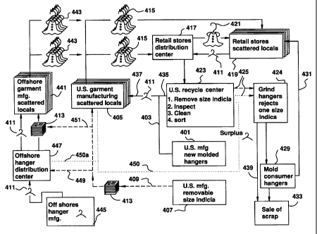
As illustrated in Figure 11, a method for
re-using hangers having size indicia removably mounted
thereon is illustrated in a schematic flowchart form.
A hanger manufacturing center 402 molds hangers and
ships the hangers via distribution channel 403 to a
plurality of garment manufacturers 405 at scattered
geographic locales. While a single group of garment
manufacturers 405 are illustrated in Figure 11, it
should be noted that in actual practice, there may be
hundreds of garment manufacturers that supply garments
to any large retail outlet.
Simultaneously, a plurality of removable
size indicia are molded at 407 and shipped in bundles
413 of size indicia via distribution channel 409 to
these same garment manufacturers 405.
At each of the plurality of garment
manufacturers 405, a single hanger 411 and a single
index cap from bundle 413 are assembled with the
garment manufactured by the U.S. garment manufacturing
facility at that geographic local. The size indicia
represents at least one characteristic of the garment,
CA 02535462 1997-05-06
-43-
and preferably indicates the size of the garment as
1 denoted in the country in which the retail store to
which the garment is to be shipped, is located. A
plurality of hangers, garments and size indicia are
then batched as illustrated at 415, and the batch is
shipped to a retail store 419 or a regional
distribution center 417 operated by the retail store
chain 419.
The regional distribution center 417
provides a supply of garments on hangers 421 to the
various retail stores 419 at scattered geographic
locations for sale to consumers. At the point of sale
in the retail store 419, the garments are removed from
the hangers and the hangers 411 are returned to the
regional distribution center 417. It is preferred
that the hangers are shipped to the distribution
center in collapsible pallet-sized boxes with plastic
lids. While it is preferable to return all of the
hangers to the regional distribution center 417, it is
noted that in actual practice, from 10-250 of the
hangers shipped from the distribution center to the
retail store as garments on hangers 421 are not
returned, but are sold with the garment to the
consumer, or are damaged or otherwise lost in use.
At the regional distribution center 417, the
2~ hangers are batched and sent to the recycle center
423, again preferably in the collapsible pallet-sized
boxes, where the removable size indicia are removed,
and the hangers are inspected and sorted by size and
type, and then cleaned.
35
CA 02535462 1997-05-06
-44-
In a preferred embodiment of the invention,
1 the size indicia are automatically removed as
previously described with respect to Figures 7 and 8.
At the recycle center 423 it has been found
that from 10-300 of the hangers returned are no longer
suitable for reuse because of excess wear, breakage,
warpage, gum tags or other debris which can not easily
be removed.
The hangers that fail the inspection and the
index caps are returned via distribution channel 425
IO to a location which grinds or granulates the hanger
rejects and index caps as illustrated at 427. At
location 427, the hangers are also separated to
classify the hangers according to the material from
which they were molded, with polypropylene and
polystyrene being the two primary materials from which
hangers are molded. The polypropylene granulated
material is then used to mold consumer hangers as
indicated at 429 which may be returned by a
distribution channel 431 for sale to consumers. The
remaining material not suitable for remolding is sold
as scrap as indicated at 433.
At the recycle center 423, it has been found
that from 30-50°s of the hangers that originally
entered the recycling loop at 403 are available for
redistribution. The hangers 411, without any size
indicia matter thereon, are then reshipped to the
garment suppliers 405 as part of the order fulfillment
at supply line 435. The supply of hangers at 435 is
augmented by freshly molded hangers as indicated at
403 and the combined stream of recycled and new
CA 02535462 1997-05-06
-45-
hangers 437 is returned to the garment suppliers 405
1 as indicated in Figure 11. It is contemplated that
each hanger will pass through the loop 2 to 6 times
before it becomes unrecoverable. The hangers shipped
from the recycle center 423 for reuse can be shipped
to either US or offshore garment manufacturers.
However, since it is contemplated that only 50-80a of
the originally molded hangers will be reused the
supply may only be sufficient to meet the demands of
the closer, in this instance, the US garment
manufacturers. The cost of molding vs. shipping
internationally must also be taken into consideration
when dealing with offshore garment manufacturers.
However, the higher shipping costs are often
outweighed to meet a particular customer's demand in
an offshore country.
Simultaneously therewith, a new plurality of
removable size indicia are molded at 407 and shipped
via channel 409 to the garment manufacturers 405 to be
reassembled with the hanger arriving from product
stream 437.
At the present time, it has been found that
the labor and material handling required to sort the
removable size indicia at the recycle center 423 is
more expensive then newly molding the removable size
indicia at step 407. Not only are the removable size
indicia molded in a plurality of colors, but each of
the colors may represent as many as ten different
sizes as herein before previously described. In
addition to the sorting, the removable size indicia
must be inspected, and reassembled into a magazine or
CA 02535462 1997-05-06
-46-
plurality of stacked caps suitable for automated
1 assembly with the hangers and garments at the garment
manufacturers 405. Consequently, in the normal course
of proceeding, the removable size indicia are ground
at step 427 and sold as scrap at step 433 as indicated
by channel 439. However, it is possible for the size
indicia to be sorted at the recycle center 423 and
then shipped back to the garment manufacturers for
reuse.
Presently, a significant percentage of
garments sold in the retail stores 419 are
manufactured off shore in areas such as China,
Thailand, India, Ceylon, Turkey and countries of the
Near East. These offshore garment manufacturers are
indicated at 441 and provide essentially the same
l5 function as the domestic manufacturers indicated at
405 inasmuch as each of these entities manufactures a
garment, and then assembles a hanger 411, an index cap
from the bundled stack 413 and the garment in an
automated production line to form a product known as
G.O.H. (Garment On Hanger) which is ready for display
in the retail stores 419. The G.O.H. garments are
then batched as indicated at 443 and shipped via
international transport, in generally intermodal or
airborne containers, to the regional distribution
center 417.
Inasmuch as the hangers, when molded
represent a substantial bulk, it is upon occasion,
less expensive to mold the hangers offshore as
illustrated at 445 and ship the hangers 411 to a
regional hanger distribution center 447, than to mold
CA 02535462 1997-05-06
-47-
and ship from the US facility 401. Regional hanger
1 distribution centers 447 may be located in such
diverse geographic locales as Hong Kong, India or
Turkey and intended to serve clusters of manufacturing
entities located within a few hundred miles of the
regional distribution center.
Batches or bundles of removable size indicia
413 are also molded at 407 and shipped via
distribution channels 409, 449 and 451 to the offshore
distribution centers 447 or offshore garment
manufacturers 441. The offshore distribution center
447 then makes separate shipments of hangers 411 and
bundles of removable size indicia 413 to the offshore
garment manufacturers 441. The offshore garment
manufacturer then assembles one of the hangers, one of
the removable size indicia and one of the garments to
provide a garment on hanger (G.O.H.) wherein the
removable size indicia corresponds to the size of the
garment.
Molding the removable size indicia at a
single location such as that indicated at 407 ensures
that the colors chosen for the removable size indicia
are consistent when they arrive at the retail stores
419 even though the adjacent garments and hangers may
have been assembled thousands of miles apart from each
other. In addition, the bulk and size of the bundles
removable size indicia 413 render them susceptible to
transoceanic shipment and use.
While in the preferred embodiment, the
removable size indicia are all molded in a single
location, it would be entirely possible to mold the
CA 02535462 1997-05-06
-48-
removable size indicia in one or more offshore molding
1 facilities, provided precise control is maintained
over the pigments used in the color indexing scheme.
There may also be a flow of returned surplus
hangers-as indicated along distribution channel 450
and 450a which may be used to augment the supply of
hangers at 435 instead of molding new hangers at 401.
In the preferred embodiment, the hanger of
the present invention is formed from styrene, k resin,
E~.I. styrene, polypropylene, other suitable
thermoplastic or combinations thereof. The indicator
of the present invention is formed from styrene or any
other. suitable plastic material.
While there have been shown and descrik>ed
what are c:onsider_ed to be the preferred embodiments of
the invention, it will, of course, he understood that
various modi.fic:.ations and changes iu form or detail
can be readily made without departing from the spirit
of the invention. It is therefore intended that_ t=lne
invention not be limited to the exact form and detail
here.i.n shown anc~ described nor to anything less t.har~
the whole of the invention herein disc_Losed as
hereinafter claimed.
30