Note: Descriptions are shown in the official language in which they were submitted.
CA 02535485 2010-07-20
METHOD AND SYSTEM FOR CONTROLLING NON-COHERENT
PULSED LIGHT
FIELD OF THE INVENTION
The present invention relates to methods and devices useful in providing
noncoherent
pulsed light. Specifically, embodiments of the present invention relate to
systems and
apparatuses that enable controlling the delivery of non-coherent pulsed light.
BACKGROUND
Light therapy generally involves applying light energy to increase the local
temperature at a target location in a body, as a result of the absorption of
photons distributed
in the target tissue. The photon distribution, and therefore local temperature
rise, is generally
determined by the features of the light source and physical properties of the
medium used for
conveying the light to a target. Selective Photothermolysis Theory (SPT),
which may be a
physical foundation for many light treatments, typically involves choosing
parameters of the
therapeutic light being used, for example, wavelength, pulse magnitude and
pulse duration,
etc., in such way that the temperature rise is sufficiently large to incur
required effects in a
target, yet remain below a safety threshold in the surrounding tissues.
SUMMARY OF THE INVENTION
There is provided, in accordance with an embodiment of the present invention,
a
system to control non-coherent pulsed light, the system including a lamp to
produce
non-coherent light energy in a pulsed mode, a power supply to provide energy
to the system,
a capacitor to generate current in the lamp; and a current modulator to
modulate energy flow
between the power supply and the lamp. The system may include a controller
unit to control
pulse parameters for a selected treatment, based on illumination data received
from the light
sensor. The system may include a switching module to modulate power supplied
to the lamp
during a pulse. The system may include one or more changeable filters to
modulate the
pulses supplied to the lamp during a pulse.
According to some embodiments of the present invention, a method to control
1
CA 02535485 2010-07-20
non-coherent pulsed light may include generating a pulse to provide treatment
to a selected
target according to a treatment plan, sensing the light output from the
target, processing
sensed signals to determine if the light output complies with predetermined
pulse parameters
and/or biological characteristics, and if the predetermined pulse parameters
and/or biological
characteristics are not being met, controlling the spectral distribution
and/or the light
intensity of the light output during a pulse.
According to some embodiments of the present invention, treatments with
multiple
modes of operation within a pulse may be implemented, to enable
differentiation between
target and surrounding tissue. Such treatments may help improve the safety
and/or efficacy of
treatments of targets located in dark skin types, of targets having physical
properties similar
to or only slightly different from surrounding tissue, of targets located deep
in the dermis,
and/or any combinations of the above treatments. Furthermore, treatment for
hair removal,
blood vessel modification, textural lesions and/or other procedures may be
aided using
treatments with multiple modes of operation within a pulse, as described
above.
In accordance with a first aspect of the present invention, there is provided
a method
of controlling spectral and intensity distribution during a pulse of non-
coherent light, the
method comprising:
initiating a pulse of non-coherent light, the pulse including a selected
spectral
distribution and a selected temporal intensity distribution; and
controlling said spectral distribution and said temporal intensity
distribution of said
pulse of non-coherent light within the duration of said pulse by, at least in
part, altering
current from a current supply provided to a lamp generating said pulse of said
non-coherent
light to cause altering said spectral distribution and said temporal intensity
distribution during
said pulse of non-coherent light;
wherein controlling said spectral distribution and said temporal intensity
distribution
comprises:
performing a determination, using a feedback mechanism, if output resulting
from
application of said pulse of non-coherent light is in accordance with pre-
determined pulse
parameters, and
changing the pre-determined parameters to alter, based, at least in part, on
the
2
CA 02535485 2010-07-20
determination of the feedback mechanism, the current from the current supply
to alter the
spectral distribution and temporal intensity distribution of said pulse of non-
coherent light
during the pulse.
In accordance with a second aspect of the present invention, there is provided
a
system to provide non-coherent pulsed light, the system comprising:
a lamp to produce non-coherent pulsed light;
a current supply to provide controlled current to said lamp, to enable
provision of
controlled spectral distribution and controlled temporal intensity
distribution of said
non-coherent pulsed light within a pulse of said non-coherent pulsed light,
the spectral
distribution in said non-coherent pulsed light and the temporal intensity
distribution of said
non-coherent pulsed light being controlled, at least in part, by altering the
current from the
current supply to cause altering said spectral distribution and said temporal
intensity
distribution during said pulse of non-coherent pulsed light; and
a feedback mechanism configured to:
perform a determination if output resulting from application of said pulse of
non-coherent pulsed light is in accordance with pre-determined treatment
parameters,
and
change the pre-determined parameters to alter, based, at least in part, on the
determination of the feedback mechanism, the current from the current supply
to alter
the spectral distribution and temporal intensity distribution of said non-
coherent
pulsed light during the pulse.
In accordance with a third aspect of the present invention, there is provided
a method
of using non-coherent light, the method comprising:
providing pre-determined pulse parameters to control spectral distribution and
temporal intensity distribution of a pulse of the non-coherent light; and
controlling said spectral distribution and said temporal intensity
distribution of the
pulse of non-coherent light within a duration of said pulse by, at least in
part, altering current
from a current supply provided to a lamp generating said pulse of said non-
coherent light to
cause altering said spectral distribution and said temporal intensity
distribution during said
pulse of non-coherent light by:
3
CA 02535485 2010-07-20
performing a determination, using a feedback mechanism, if output resulting
from
application of said pulse of non-coherent light is in accordance with the pre-
determined
parameters, and
changing the pre-determined parameters to alter, based, at least in part, on
the
determination of the feedback mechanism, the current from the current supply
to alter the
spectral distribution and temporal intensity distribution of said non-coherent
light during the
pulse.
In accordance with a fourth aspect of the present invention, there is provided
a
system to provide non-coherent pulsed light, the system comprising:
a lamp to produce non-coherent pulsed light;
a current supply to controllably provide current to said lamp and to enable
controlled
spectral distribution and controlled temporal intensity distribution of said
non-coherent
pulsed light within a pulse of said non-coherent pulsed light, the controlled
spectral
distribution and the controlled temporal intensity distribution of said non-
coherent pulsed
light being controlled, at least in part, by altering the current from the
current supply to cause
altering the spectral distribution and the temporal intensity distribution
during the pulse;
at least one changeable filter to enable separate controlled altering of the
spectral
distribution and the temporal intensity distribution of said non-coherent
pulsed light during
the pulse;
a feedback mechanism configured to:
perform a determination if output resulting from application of said pulse of
non-coherent pulsed light is in accordance with pre-determined pulse
parameters, and
change the pre-determined pulse parameters to perform, based, at least in
part,
on the determination of the feedback mechanism, at least one of altering the
current from the
current supply to alter the spectral distribution and the temporal intensity
distribution of said
non-coherent pulsed light during the pulse, and controlling the at least one
changeable filter;
and
a controller unit to control at least one of the current supply, the at least
one
changeable filter and the feedback mechanism, the controller unit being
configured to enable
control of at least one of the spectral and the temporal intensity
distribution of said
4
CA 02535485 2010-07-20
non-coherent pulsed light for the selected pre-determined pulse parameters,
based, at least in
part, on data received from said feedback mechanism.
BRIEF DESCRIPTION OF THE DRAWINGS
The principles and operation of the system, apparatus, and method according to
the
present invention may be better understood with reference to the drawings, and
the
following description, it being understood that these drawings are given for
illustrative
purposes only and are not meant to be limiting, wherein:
Figs. IA and 1B are a schematic illustrations of components of a non-coherent
pulsed
light system, according to some embodiments of the present invention;
Fig. 2 is a flow chart illustrating a method of controlling non-coherent
pulsed light
output according to some embodiments of the present invention;
Figs. 3A-3E are graphical illustrations of light output as a function of time,
according
to some embodiments of the present invention; and
Figs. 4A-4C are examples of measured spectra of light output of, for example,
a
xenon lamp, as a function of energy input according to some embodiments of the
present
invention.
It will be appreciated that for simplicity and clarity of illustration,
elements shown in
the drawings have not necessarily been drawn to scale and are being provided
as non-limiting
examples. For example, the dimensions of some of the elements may be
exaggerated relative
to other elements for clarity. Further, where considered appropriate,
reference numerals may
be repeated among the drawings to indicate corresponding or analogous elements
throughout
the serial views.
DETAILED DESCRIPTION OF THE INVENTION
The following description is presented to enable one of ordinary skill in the
art to
make and use the invention as provided in the context of a particular
application and its
requirements. Various modifications to the described embodiments will be
apparent to those
with skill in the art, and the general principles defined herein may be
applied to other
embodiments. Therefore, the present invention is not intended to be limited to
the particular
5
CA 02535485 2010-07-20
embodiments shown and described, but is to be accorded the widest scope
consistent with the
principles and novel features herein disclosed. In other instances, well-known
methods,
procedures, and components have not been described in detail so as not to
obscure the
present invention.
In the following detailed description, numerous specific details are set forth
in order
to provide a thorough understanding of the present invention. However, it will
be understood
by those skilled in the art that the present invention may be practiced
without these specific
details.
Embodiments of the present invention may provide systems and methods to enable
controlling of non-coherent pulsed light emitted by a light source, such as a
lamp, thereby
modulating the temporal distribution of the light and/or the spectral
distribution output by the
lamp within a pulse of light. The controlled current may enable, for example,
changing the
shapes of light pulses emitted by the lamp, such as, for example, squaring or
smoothing of
sub-pulses of non-coherent pulsed light, equalizing the sub-pulses, and
delivering the energy
over an extended period of time, according to a selected pulse shape or sub-
pulse related to
target specifications. The current control may enable changing of a pulse
spectrum, during a
pulse, to comply with target specifications. These developments may enable
administration
of customizable non-coherent pulsed light treatments, enabling enhanced safety
and efficacy
of such treatments. Sub-pulses, as described herein, may relate to pulses
and/or portions of
pulses that may be initiated, generated, delivered etc., according to some
embodiments of the
present invention. Pulses, as described and/or as claimed herein, may relate
to whole pulses,
partial pulses, sub-pulses or other suitable portions of pulses. For example,
the length of a
pulse and/or the combined lengths of one or more sub-pulses within a pulse may
be between
lms to several seconds.
Reference is now made to Fig. IA, which is a schematic illustration of a
system 100
enabled to control non-coherent pulsed light applications, such as, for
example, Intensed
Pulse LightTM (IPLTM) based skin treatments. As can be seen in Fig. 1, system
100 may
include a power supply 105, which may include, for example, an electric power
source, e.g.,
a battery or any other suitable source of electric power. A current source,
for example a
capacitor 110, may be provided to store a charge, and may be subsequently
periodically
6
CA 02535485 2010-07-20
discharged to generate current, which may be used to operate a lamp 135
producing
non-coherent light energy in a pulsed mode. Power supply 105 may be connected
to lamp
135 directly or via a current regulator and/or modulator 115, as described
below. Lamp 135
may be operated in a pulsed mode, and may provide, for example, non-coherent
pulsed light
to one or more targets. Lamp 135 may include, for example, a xenon, krypton or
any other
light source that may generate a wide wavelength spectrum of light energy
output. For
example, an exemplary lamp 135 may provide light energy with wavelengths
ranging
between 300-1100 nanometers. Lamp 135 may be associated with at least one
light sensor
unit 130, to sense, for example, light intensity and/or light wavelengths in a
vicinity of lamp
135. Light sensor unit 130 may be independent of lamp 135, or integrated into
lamp 135. In
other embodiments light sensor unit 130 may sense, for example, light
intensity and/or light
wavelengths reflected from a treatment area, for example, a body surface.
Current regulator and/or modulator 115 may be used to modulate energy flow
(e.g.,
electric pulses) between power supply 105 and lamp 135 and/or between
capacitor
110 and lamp 135. Current regulator/modulator 115 may include a controller
unit 120, and a
switching module 125. Controller unit 120 may be independent of current
regulator 115 (as
shown in Fig. 1), and/or in other embodiments may be included within current
regulator 115
or within other suitable system components. Switching module 125 may be
adapted to
modulate the power supply or current provided to lamp 135, to effect changes
in spectral
distribution and/or light intensity emitted from lamp 135. Controller unit 120
may include a
data storage unit (not shown), which may store executable code, non-coherent
pulsed light
data, treatment data, user data, and/or other relevant data. For example,
pulse parameters for
a treatment (including shape, energy, spectrum during different portions of
pulse, etc.) may
be prepared, according to the resolution of optical parameters between a
target and the
surrounding tissue. Such parameters may be stored in controller unit 120.
Controller 120 may
translate the pulse parameters to system parameters, such as capacitor
voltage, lamp current
etc., possibly using suitable software.
Controller 120 may be adapted to process illumination data received from light
sensor
130. Results of the processing of data from light sensor 130 by controller 120
may be used to
instruct switching module 125 to activate lamp 135 with a controlled current
pattern. For -
7
CA 02535485 2010-07-20
example, switching module 125 may provide an appropriate current pattern to
generate a
temporal distribution of light, and a selected wavelength spectrum of light
energy during a
pulse from lamp 135. Controller 120 may, for example, determine the wavelength
spectrum
to be generated, thereby enabling spectrum switching during a pulse and/or
during a
sub-pulse, as described below with reference to Figs. 4A-4C. Switching module
125 may
include a current control module, to control the magnitude of current supplied
to lamp 135.
Such current control may affect the spectrum emitted by lamp.
A light conducting material 145, such as a light guide, gel or any combination
thereof, or any other suitable material, may be placed on a body surface 150,
to enable
energy emitted by lamp 135 to flow efficiently to body surface 150. In some
embodiments,
efficient energy flow may be achieved by connecting current regulator 115 or
modulator 125
directly to power supply 105, e.g., not via capacitor 110. In some
embodiments, efficient
energy flow and/or control over current delivered to lamp 135 may be achieved
by using
filters, for example, changeable or variable filters 140. Filters 140,
however, may be changed
according to a pre-determined plan, without feedback. According to one
embodiment of the
present invention, results of the processing of data from light sensor 130 by
controller 120
may be used to control operation of filters, for example, to change pulse
wavelengths within
a pulse. Filters 140 may include, for example, cut on filters, cut off
filters, band pass filters,
neutral density filters, and/or any other suitable filters having one or more
different light
spectrum and/or light intensity capabilities.
In other embodiments, as can be seen with reference to Fig. 1B, system 100 may
be
provided with energy by a current supply 117, which may supply current at
selected
durations, intensities, or other selected criteria.
Fig. 2 schematically illustrates a method of controlling non-coherent pulsed
light. As
can be seen in Fig. 2, at block 200 a treatment plan may be prepared, for
example, using a
processing unit associated with treatment software. For example, treatment
software may
enable preparation of treatment pulse parameters, such as shape, energy, and
spectrum etc.,
during the different portions of a pulse and/or a sub-pulse, according to
optical and/or
biological properties of a target and/or of surrounding tissue. At block 205
the pre-defined
pulse parameters may be translated into system parameters, such as capacitor
voltage, lamp
8
CA 02535485 2010-07-20
current etc., for example by a processing unit associated with treatment
software. At block
210 a pulse may be initiated, for example, using a power supply to a charge
capacitor to
generate one or more pulses, to activate a lamp. Current may be supplied
directly to the lamp
from the power supply, for example, not via the capacitor. At block 215 system
100 may
determine whether or not to operate with sensor feedback, for example using a
controller.
Pulse(s) may be operated in a plurality of modes, or in any combination of
modes. In
a first mode, indicated by block 220, the method may be implemented using
sensor feedback
("YES" at block 215). The light output that may be sensed by a sensor, for
example, a light
sensor, may be received and processed by the controller. The light sensor may
sense
parameters such as light intensity, light wavelengths etc. Other sensors, for
example current
sensors or tissue temperature sensors etc. may also be used. At block 220, the
controller may
process signals from the sensor, to determine if the light output complies
with predetermined
pulse parameters and/or biological characteristics. At block 220, if the
predetermined pulse
parameters are being met ("YES" at block 220), a current regulator may enable
a continued
generation of pulses and/or sub-pulses according to the initial predetermined
treatment pulse
parameters, at block 230. At block 225, if the predetermined pulse parameters
are not being
met ("NO" at block 220), the controller may control the lamp current and/or
light output,
thereby determining the lamp output during a pulse. In this way, the adjusting
of electrical
input parameters may enable compliance of a pulse and/or a sub-pulse to
predetermined
pulse parameters and/or biological characteristics. For example, a switching
module may
increase or decrease the current to the lamp, optionally during a pulse, to
increase, decrease,
or maintain the light output from the lamp at selected levels. For example,
changing the
current during a pulse and/or during a sub-pulse may enable spectrum shifting
of light
emitted by the lamp during a pulse and/or during a sub-pulse, and/or changing
of temporal
distribution of light emitted by the lamp during a pulse and/or during a sub-
pulse.
In a second mode, indicated by block 230, the method may be implemented
without
using sensor feedback ("NO" at block 215), according to the predetermined
treatment plan.
At block 240, the controller may determine whether or not to end the pulse. At
block 250, if
the controller determines to end the pulse ("YES" at block 240), pulse
generation may be
stopped. At block 260, if the controller determines to continue the pulse
("NO" at block 240),
9
CA 02535485 2010-07-20
controller may determine whether or not future portions of a pulse require
changing of filters.
At block 270, if the controller determines to operate with changeable filters
("YES" at block
260), filters may be changed at predetermined time intervals during a pulse.
At block 270, the
method may continue from block 215, where a decision whether to operate a
subsequent
pulse portion with or without feedback may be determined. At block 260, if the
controller
determines to operate without changeable filters ("NO" at block 260), the
method may
continue from block 215, where a decision whether to operate a subsequent
pulse portion
with or without feedback may be determined. For example, a spectral filter,
such as a cut on,
cut off, band pass or other filter, may be used with the lamp at a constant
current. For
example, a neutral density filter may be used to control the temporal shape of
the pulse
and/or a sub-pulse, during the pulse, without making spectral changes. Any
combination of
some or all of the above functions, as well as additional suitable functions,
may be
implemented.
In this way, the pulse shape representing the light output from the lamp may
be
controlled to comply with target specifications. For example, if the light
intensity is too high,
or the spectrum being illuminated by the lamp is out of the required spectrum
limits for a
target being treated, the regulator may control the energy supplied to the
lamp during a pulse
to generate the required light output, for example, according to a selected
spectrum, a
selected pulse length, and/or a duty cycle. Carefully tuned pulses and/or sub-
pulses may
produce considerable temperature rises at the target, while maintaining
temperatures in
adjacent tissues well below a selected safety threshold. For example, changing
the spectral
distribution may enable outputting a significant quantity of light energy in a
yellow light
range, for example, by increasing the current. In addition, for example, the
current may be
lowered and a short (e.g. 500nm) cut-off filter may be used, thereby
maintaining most of the
light in the safer IR region of the spectrum. Later during the pulse, the
current may be
increased to enable shifting of the spectrum towards the yellow visible light
range.
According to an embodiment of the present invention, target tissue parameters
may
be measured during a pulse, and pulses or sub-pulses may be adjusted during
the pulse to
optimize the treatment. Both spectrum distribution and time dependence of
pulse amplitudes
may be varied according to the type, position, and dimensions of a selected
target, or
CA 02535485 2010-07-20
modifications of target parameters during treatment. Such operations may
enable optimal
light energy to be applied to selected targets, providing relatively efficient
and safe usage of
light energy to treat target locations.
According to some embodiments of the present invention, at least one physical
property may be defined that differentiates between one or more targets and
surrounding
tissue, to enable increasing the targeted effect of treatment, while
preserving the surrounding
tissue. For example, altering the resolution of optical parameters between a
target and the
surrounding tissue may enable differentiation of targets located in dark skin
types, targets
having physical properties similar to or only slightly different from -
surrounding tissue,
targets located deep in the dermis, and/or combinations of the above. Such
differentiation
may enable, for example, increased safety and/or efficacy when applying
treatments
including hair removal, blood vessel treatments, textural lesion treatments
etc.
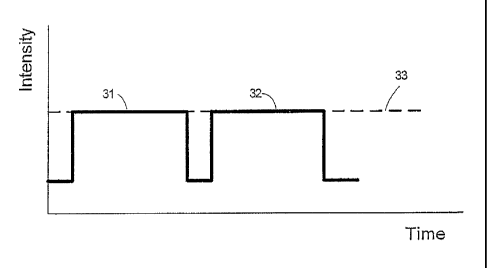
Reference is now made to Figs. 3A-3E, which schematically illustrate light
energy
outputs, according to some embodiments of the present invention. As can be
seen with
reference to Fig. 3A, traditional non-coherent pulsed light pulse shapes or
sub-pulse shapes,
such as pulses 31 and 32, may be characterized by an energy peak at the
beginning of the
pulse, or sub-pulse, followed by a rapid decline in the energy delivered to a
target. Such
energy output patterns may generally result from insufficient control of the
discharge from a
capacitor 110. Energy supplied above an optimal level 33, represented by area
34, may be,
for example, dangerous and/or unusable energy. Energy levels below optimal
level 33,
represented by area 35, may relate to energy deficiencies as a result of
outputs from a
capacitor that are too low to impact effectively on a target.
Figs. 3B-3E, for example, illustrate various examples of pulse shapes that may
be
provided by a light source producing non-coherent pulsed light, such as lamp
135, according
to some embodiments of the present invention. As described above, controller
120, in
association with capacitor 110, current regulator 115, and/or switching module
125 may
provide pulses of energy that may be controlled, for example to produce pulses
and/or
sub-pulses of selected durations, intensities etc. In Fig. 3B, for example,
the subpulses 31, 32
have been squared or smoothed to optimal level 33, according to selected
values, thereby
equalizing the energy emitted by the sub-pulses. Fig. 3C illustrates an
example of an
11
CA 02535485 2010-07-20
extended pulse, which may be a relatively long and relatively low power pulse.
For example,
relatively long square pulses may enable lamp 135 to operate at a low current
(e.g., with a
low plasma temperature), which may lead to spectral distribution with, for
example, a
maximum wavelength of between 890 and 1000 nm. Such a shift of the non-
coherent pulsed
light output may be used to provide relatively high safety levels for non-
coherent pulsed light
treatments. For example, treatments for darker skinned people may require
relatively longer
exposure, by giving fluence over an extended period of time. Such a system may
therefore
enable relatively safer treatment of dark skinned people, though possibly at a
lower efficacy
yield. As can be seen in Figs. 3B-3C, electric energy supplied to the lamp may
be controlled
to provide a selected light intensity, represented by line 33.
According to some embodiments of the present invention, a multiple stage non-
coherent pulsed light treatment may be provided. For example, a light output
from a
lamp may be used to enable pre-heating of a target. The light output, for
example, according
to the pulse length or spectrum, may be adapted to enable implementation of a
selected
treatment at the target. Examples of multi-stage treatments may be seen with
reference to
Figs. 3D-3E. Fig. 3D illustrates an example of a relatively long, low power,
pre-heating IR
shifted pulse followed by a high impact pulse (e.g., towards green/yellow wave
length).
Fig. 3E illustrates an exemplary customized controlled pulse. Such a pulse, as
can be
seen in Fig. 3E, may provide improved safety and efficiency, as it may be
tailored or
customized according to target and skin type, or any other factors. For
example, a
non-specific heating of tissue, from the deeper to the more superficial zones,
together with a
chilling procedure that may further cool the epidermis during the noncoherent
pulsed light
procedure, may be administered. Of course, other pulse types and dimensions
may be used.
Any number of stages, or combinations of stages, may be used.
In some embodiments the preheating pulse may be, for example, be used to
implement non-specific heating of one or more targets and surrounding tissue.
Preheating
may utilize, for example, pulses in the red-infrared range. A subsequent
treatment pulse or
sub-pulse may be utilized. Such a treatment pulse may be, for example, in the
yellow-blue
spectrum range (e.g., 400-600nm). Other suitable ranges may be used.
In the case of treatments using changes in spectral distribution, the length
of the pulse
12
CA 02535485 2010-07-20
or of the total sub-pulses may be, for example, between lms up to 1 sec. The
change of the
related spectral distribution may be, for example, between 300 and 1,500nm.
The controlled
change of spectral distribution may be implemented by precisely controlling
the current
provided to the lamp, and/or by using flying or changing filters.
In the case of treatments using changes in light intensities, the length of
the pulse or
of the total sub-pulses may be, for example, between lms up to 1 sec. The
current provided to
the lamp may be, for example, between 10 and 600 Amps. In some embodiments the
current
density may be, for example, between 100-4000 Amps/cm2, or the plasma
temperature may
be, for example, between 1,000 to 12,000 K.
According to some embodiments of the present invention, treatments with
multiple
modes of operation within a pulse may enable differentiation between one or
more targets
and surrounding tissue. Such treatments may help improve the safety and/or
efficacy of
treatments of targets located in dark skin types, of targets having physical
properties similar
to or only slightly different from surrounding tissue, of targets located deep
in the dermis,
and/or any combinations of the above treatments. Furthermore, treatment for
hair removal,
blood vessel modification, textural lesions and/or other procedures may be
aided using
treatments with multiple modes of operation within a pulse, as described
above.
Reference is now made to Figs. 4A-4C, which are graphs illustrating examples
of
spectral distribution of light output from a light source producing non-
coherent pulsed light,
such as lamp 135, for different current input (in Amperes), for example,
delivered from
power supply 105 or capacitor 110 to lamp 135. As can be seen in Fig. 4A, when
providing a
pulse of 350 Amperes (A), for example, the resulting output from lamp 135 may
provide a
certain spectrum and light intensity. When providing a pulse of 200A, for
example, as can be
seen in Fig. 4B, the resulting output from lamp 135 may provide a shift in
spectrum and light
intensity. When providing a pulse of 100A, for example, as can be seen in Fig.
4C, the
resulting output from lamp 135 may provide further shift of the spectrum and
light intensity.
Generally, Figs 4A-4C show a shift in the spectrum towards the infrared
wavelengths,
resulting from the change (reduction) of current supplied to the lamp and/or
the change of
intensity. These phenomena may be formed during pulses, using methods and
devices of the
present invention.
13
CA 02535485 2010-07-20
According to some embodiments of the present invention, regulator 125 may
enable
modulation of the output to lamp 135, such that a selected output may be
provided to lamp
135. This selected output, according to an embodiment of the present
invention, may be, for
example, a suitable mixture or combination of the current inputs described
with reference to
figs. 4A-4C, or other current inputs. A controlled current input as described
above may
enable emission of light energy according to the requirements of one or more
selected
targets. For example, the output may be controlled to yield a relatively
constant light
intensity, a predetermined spectrum, selected pulse duration or sub-pulse
duration, a desired
duty cycle, a combination of pulses, and/or other selected pulse parameters.
The ability to
change a spectrum of outputted light energy may be referred to as spectrum
switching,
which, according to some embodiments of the present invention, maybe
implemented within
a pulse.
According to some embodiments of the present invention, two-part pulses, for
example, may be used to control light output for a given treatment, for
example, for wrinkle
reduction. For example, in a first operation a low power, long duration, pulse
may be
generated for preheating at a low plasma temperature (e.g. using light in the
infrared
spectrum). During this operation the tissue may be heated to just below a
damage threshold,
for example, in a non-selective way, to a depth. of up to approximately 2mm.
Simultaneously, cooling, for example contact cooling, may be applied to
decrease the
temperature of a treatment area, for example the epidermis. In a second stage,
a relatively
short, higher power, pulse may be generated. The plasma temperature during the
second
stage may be chosen, for example, to match the absorption of hemoglobin. In
such a case, the
temperature around small capillaries may increase to a level, where, for
example, collagen
re-generation may occur, which may lead to skin rejuvenation.
According to some embodiments of the present invention, two-part or multi-part
pulses, as described above, may be used to control light output for, for
example, effective
treatment of medium size blood vessels. For example, a first sub-pulse may be
generated
with high power for a short duration, with most of the light in the green
yellow spectral
region. This sub-pulse may initiate, for example, a red shift of blood
absorption. A second
sub-pulse that is tuned to emit infrared light may be generated, which may be
less dangerous
14
CA 02535485 2010-07-20
to the epidermis.
According to some embodiments of the present invention, mechanical filters may
be
changed during a pulse, in addition to current change, or in any combination.
The usage of
filters may refer to changeable filters, flying filters, or other suitable
filters that may have
different light spectrum filtering characteristics and/or different light
intensifying
characteristics, to enable control of non-coherent pulsed light during a
pulse. The mechanism
for controlling the changeable filters may be similar to a mechanical camera
shutter. Such
filters may be used with or without a switching module 125 to change the pulse
shape
emitted from lamp 135, during a pulse. For example, a spectral filter, such as
a cut on, cut
off, band pass or other filter, may be used with lamp 135 operated at a
constant current, to
change the spectrum emitted during a pulse. For example, a neutral density
filter may be used
to control the temporal shape of the pulse without making spectral changes.
The foregoing description of the embodiments of the invention has been
presented for
the purposes of illustration and description. It is not intended to be
exhaustive or to limit the
invention to the precise form disclosed. It should be appreciated by persons
skilled in the art
that many modifications, variations, substitutions, changes, and equivalents
are possible in
light of the above teaching. It is, therefore, to be understood that the
appended claims are
intended to cover all such modifications and changes as fall within the true
spirit of the
invention.